I. Introduction
Passive coherent location (PCL) systems based on non-cooperative sources such as FM and TV signals have been developed successfully in recent years [1–4]. The purpose of a PCL system is to detect and track airborne targets using a reference and a surveillance channel. The reference channel, used to obtain commercial broadcast signals, should steer the beam toward a base station, and at the same time the surveillance channel should have a radiation pattern that includes deep null toward the base station. From the correlation between the signals of the two channels, targets can be detected and tracked [5, 6]. However, in general, echo signals reflected from potential targets are extremely weak and are obscured by strong direct signals. To increase the detectability of echo signals by minimizing the terrestrial multipath effect and other clutters, interference suppression techniques that support the accuracy of direction-of-arrival information are typically used [7–10]. In addition, the probability hypothesis density and the multi-frame assignment have been proposed to enhance the detection performance of PCL systems [11–13]. Their performance can be further optimized by improving the performance of the antennas employed in PCL systems. For example, antenna elements with multiband and dual polarization characteristics have been designed to increase the probability of target detection by expanding the operating frequency and available polarization. Although studies aiming to determine the optimal beam pattern of the array for PCL systems according to various array configurations have also been conducted [14, 15], they are limited to certain canonical forms of array configurations. Other studies have performed optimizations of array configurations using various optimization methods, such as the particle swarm algorithm [16], the invasive weed algorithm [17], and the genetic algorithm [18]. However, non-uniform array configurations that can effectively improve the array performance of PCL systems have not been sufficiently considered.
In this paper, we propose a non-uniform array configuration to maximize the beamforming performance of PCL systems. The proposed array consists of eight dipole elements divide into two groups with different distances from the array center. This double-layered non-uniform configuration is used to observe the trends of beamforming performance for various array configurations. Each element is designed and fabricated to operate in the FM frequency band, and the antenna performance required for PCL systems are examined. The array antenna characteristics—peak-to-side lobe ratio (PSLR), first null bandwidth (FNBW), null width, and null depth—are then investigated to derive the optimum array configuration. Parametric studies of various array distances are conducted, and the optimal configuration is determined by evaluating the cost function of the beamforming performance. To verify the performance enhancement of the proposed array, the reference and surveillance beams are compared with the conventional uniform circular array (UCA). The results demonstrate that the proposed non-uniform array configuration has more suitable beam patterns compared with the conventional UCA. The target detection performance of the proposed array for PCL systems is tested in a certain scenario.
II. Design of the Dipole Element
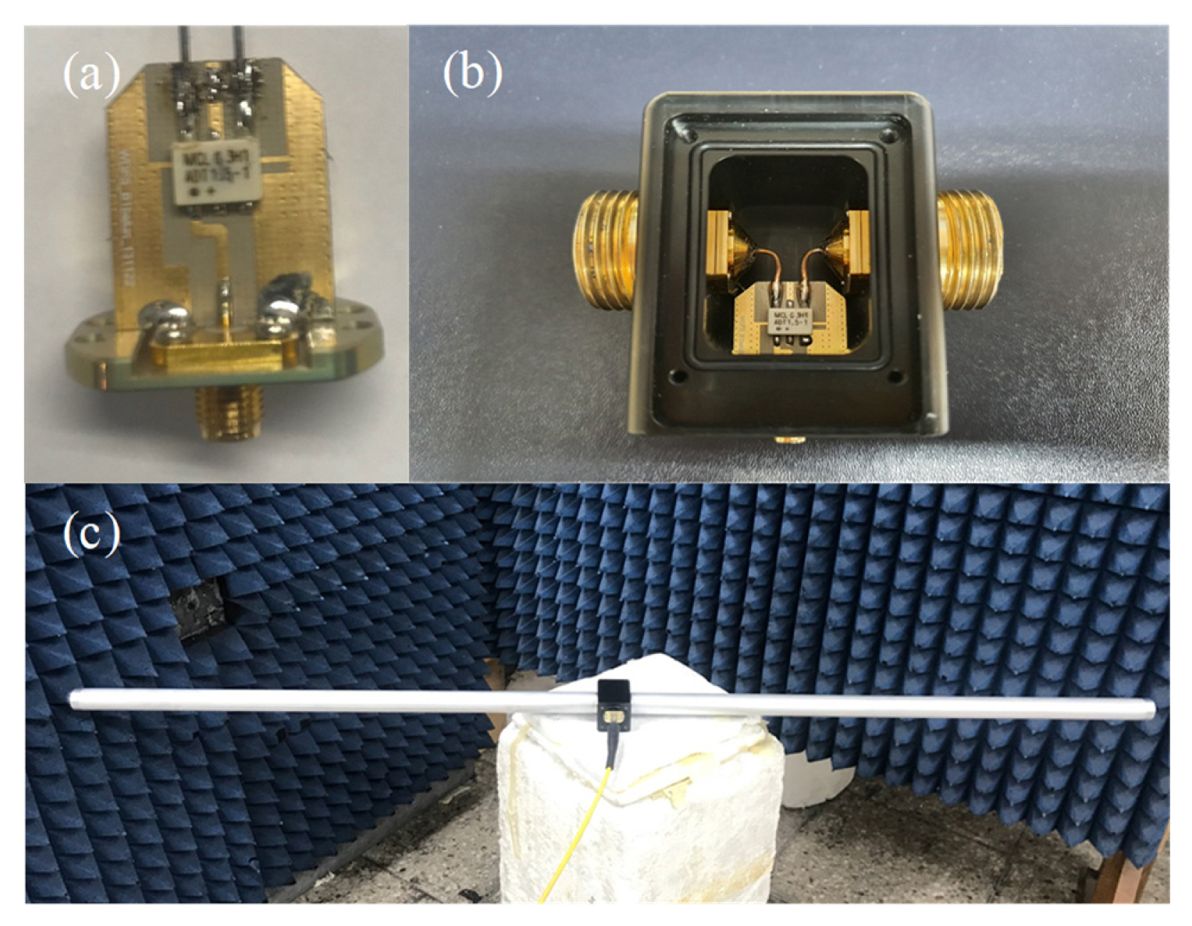
Fig. 1 shows a photograph of the fabricated dipole element with a broadband balun (ADT1.5–1+, Mini-Circuits) embedded in the circuit board. The balun operates in a range from 1 to 300 MHz with an insertion loss of less than 1 dB. This structure can help minimize the pattern distortion by the unbalanced current of the coaxial feed while maintaining the broadband matching characteristics. Thanks to its compact size (7.9 × 5.6 × 2.8 mm3), the balun can be mounted on a board, as shown in Fig. 1(a) and (b). It provides the housing structure with the circuit board to protect the circuit from external physical shocks while reliably attaching the dipole antenna to it. The fully manufactured dipole with the housing is shown in Fig. 1(c). The length and radius of the dipole are h = 134 cm and r = 7.5 mm, respectively.
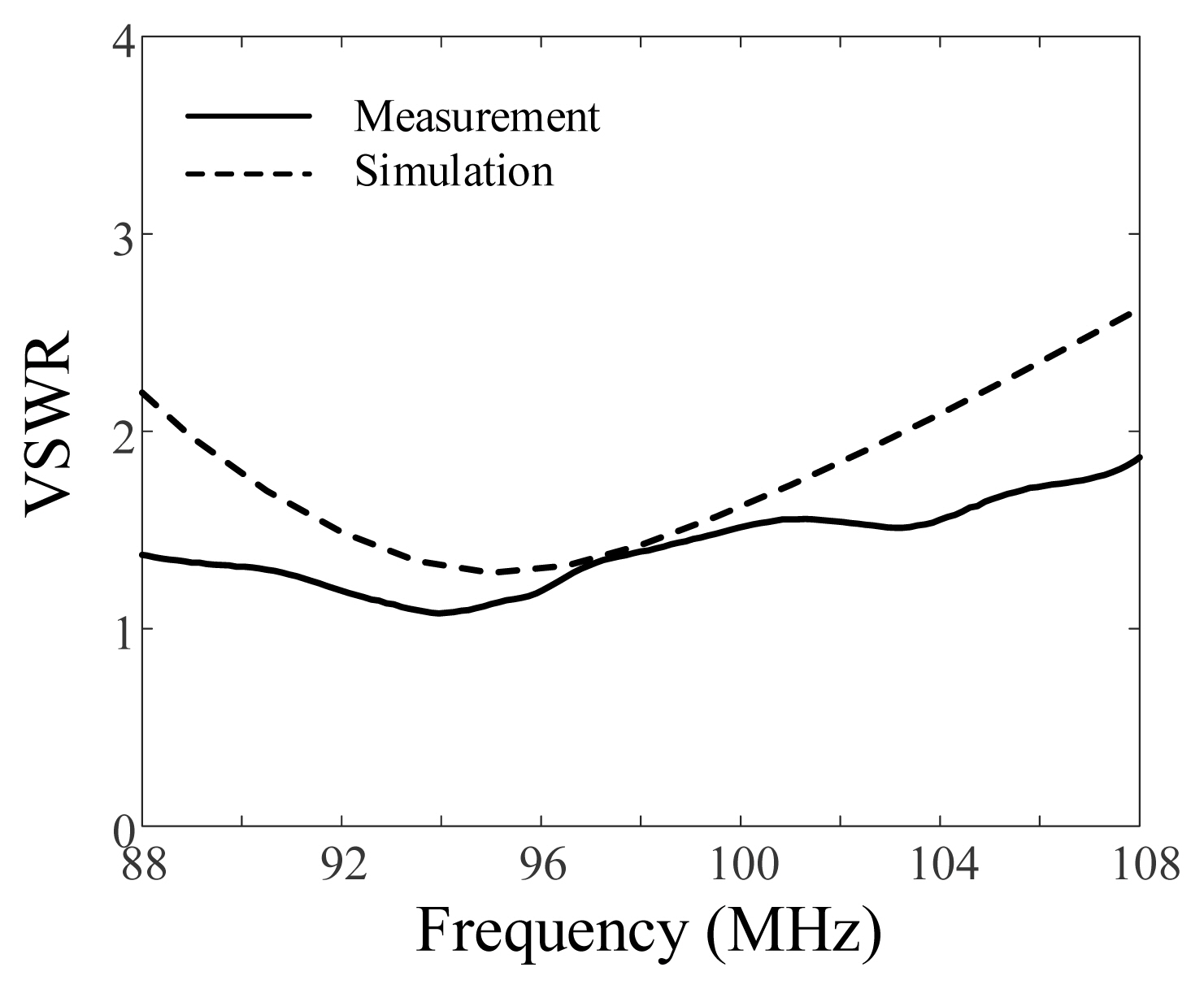
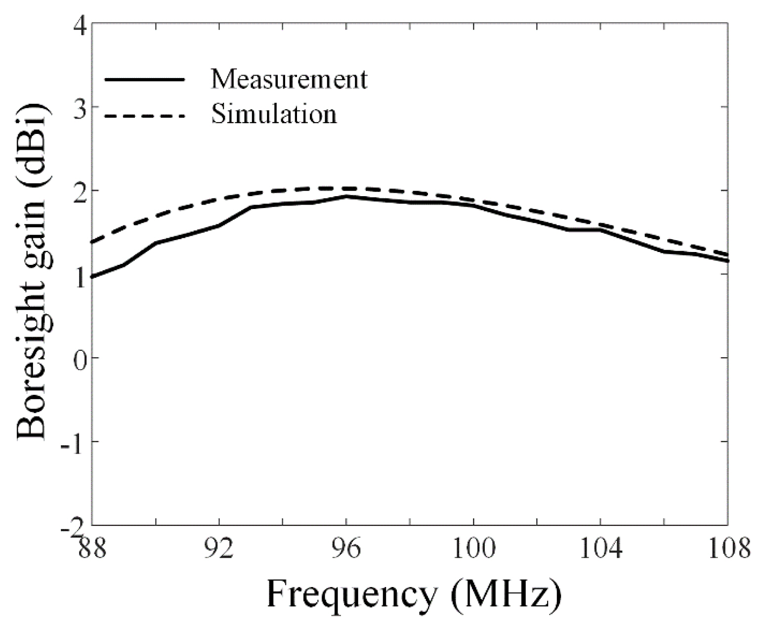
Fig. 2 provides a comparison of the measured and simulated voltage standing wave ratios (VSWRs) of the proposed dipole element (solid and dashed lines, respectively). The measurement is performed in a semi-anechoic chamber, resulting in a bandwidth of 23 MHz (from 85 MHz to 108 MHz, VSWR <2) with a fractional bandwidth greater than 23%. The fractional bandwidth of the simulated VSWR is 17%, which shows good agreement with the measured data. Fig. 3 illustrates the boresight gain as a function of frequency. The solid line represents the measured data, which maintains a gain above 1 dBi from 88 to 108 MHz. The simulation values are similar to the measured values, with differences less than 0.5 dB. These results show that the performance of the designed dipole element is suitable for a PCL system.
III. Proposed Array Configuration
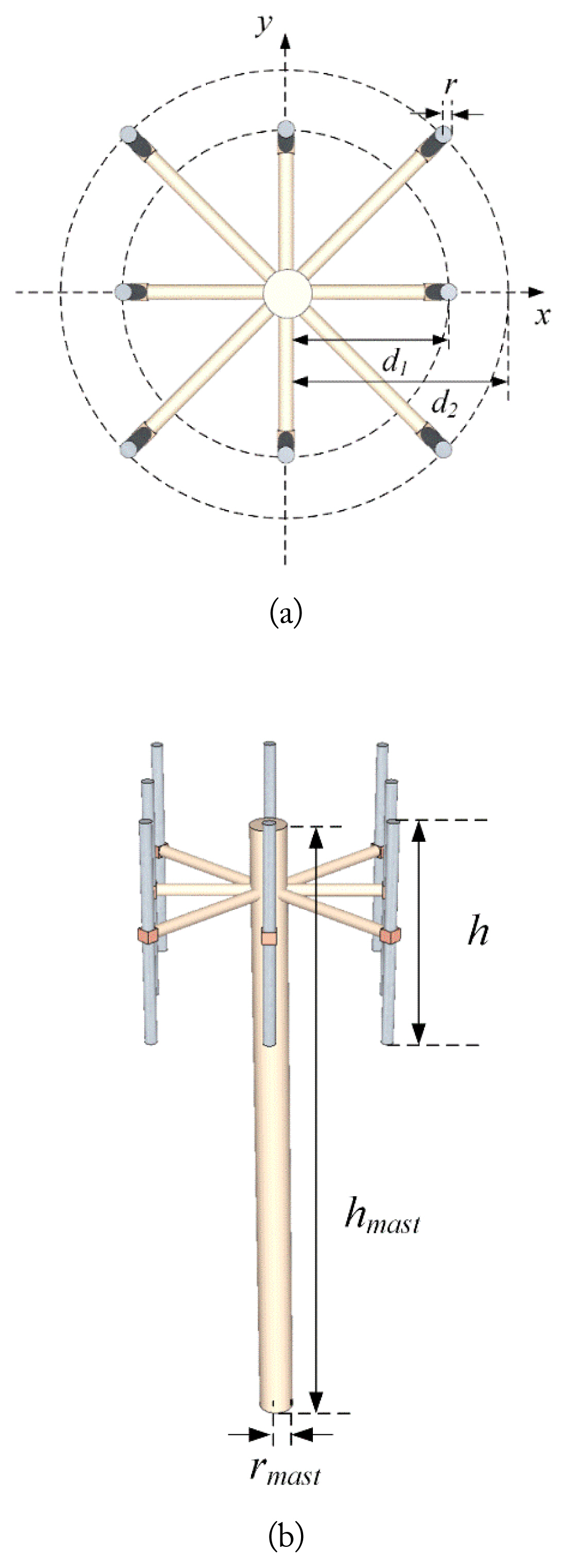
Fig. 4 shows the geometry of the proposed non-uniform eight-element array for PCL systems. It consists of two groups (inner and outer layers) with different distances d1 and d2 from the array center, as shown in Fig. 4(a). The expandable mast with length hmast and radius rmast is used to mount the array elements. WIPL-D Pro electromagnetic simulation software (WIPL-D, Belgrade, Serbia) is used to optimize and analyze the proposed configuration. The optimum design parameters are displayed in Table 1.
To effectively detect targets, the array antenna of the PCL system must be able to generate two different channels: the reference and the surveillance channel. Since PCL systems are passive radar systems that do not generate a reference signal, commercial broadcast signals from FM base stations are often used as reference signals for detecting targets. Therefore, the beam pattern of the reference channel should have a higher PSLR and narrower FNBW to obtain only the reference signal from the base station. However, the beam pattern of the surveillance channel requires a greater null depth and a narrower null width toward the base station. This is because the surveillance channel should only receive scattered signals from targets without the reference signals. The optimum array configuration is derived by considering the beam patterns of the reference and surveillance channels. The mask functions for the reference and surveillance beams are used to obtain the optimized beam patterns [15]. The mask function F(φ) can be calculated as
where A and ω are the array manifold and weightings to create the beam pattern of the proposed non-uniform array, respectively. The weightings for the beam pattern are then calculated with the following equation:
From Eq. (2), we can derive the weightings ω that can minimize the square error between the pattern and the mask function. Since the FM band ranges from 88 to 108 MHz, the array characteristics of the PSLR, FNBW, null depth, and null width are examined at three specific frequencies: 88, 98, and 108 MHz. The cost function to assess array performance is defined to achieve the optimal array configuration as follows:
where Costr and Costs are the cost functions of the reference and surveillance beams, respectively. These costs are computed using the PSLR, FNBW, null depth, and null width. Weight constants of α = 0.8, β = 0.5, γ = 0.2, and δ = 0.5 are used in the optimization. Lower cost means more appropriate beam pattern.
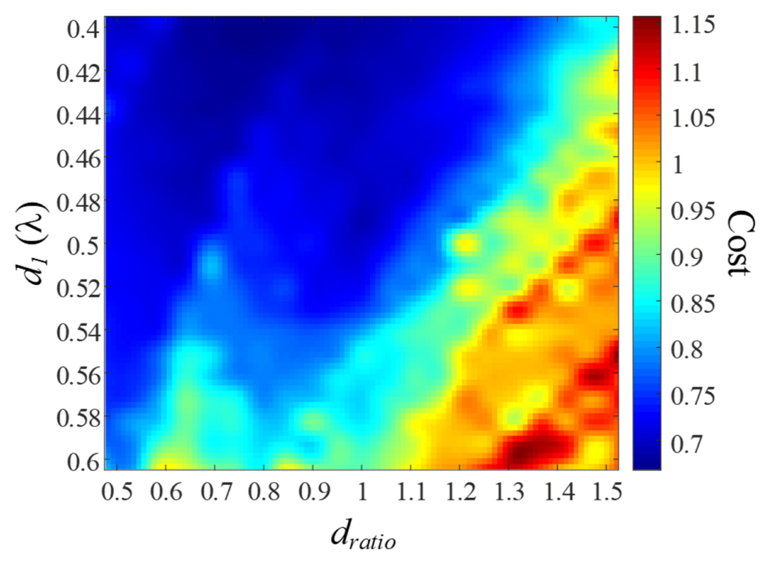
Fig. 5 illustrates the total cost map according to d1 and dratio. d1 is changed from 0.4λ to 0.6λ at intervals of 0.01λ, and dratio is varied from 0.5 to 1.5 with intervals of 0.05. The minimum cost of 0.67 is obtained when d1 and dratio are 0.41λ and 0.8, respectively, while a cost of 0.7 is observed with the UCA configuration (d1 = d2 = 0.5λ).
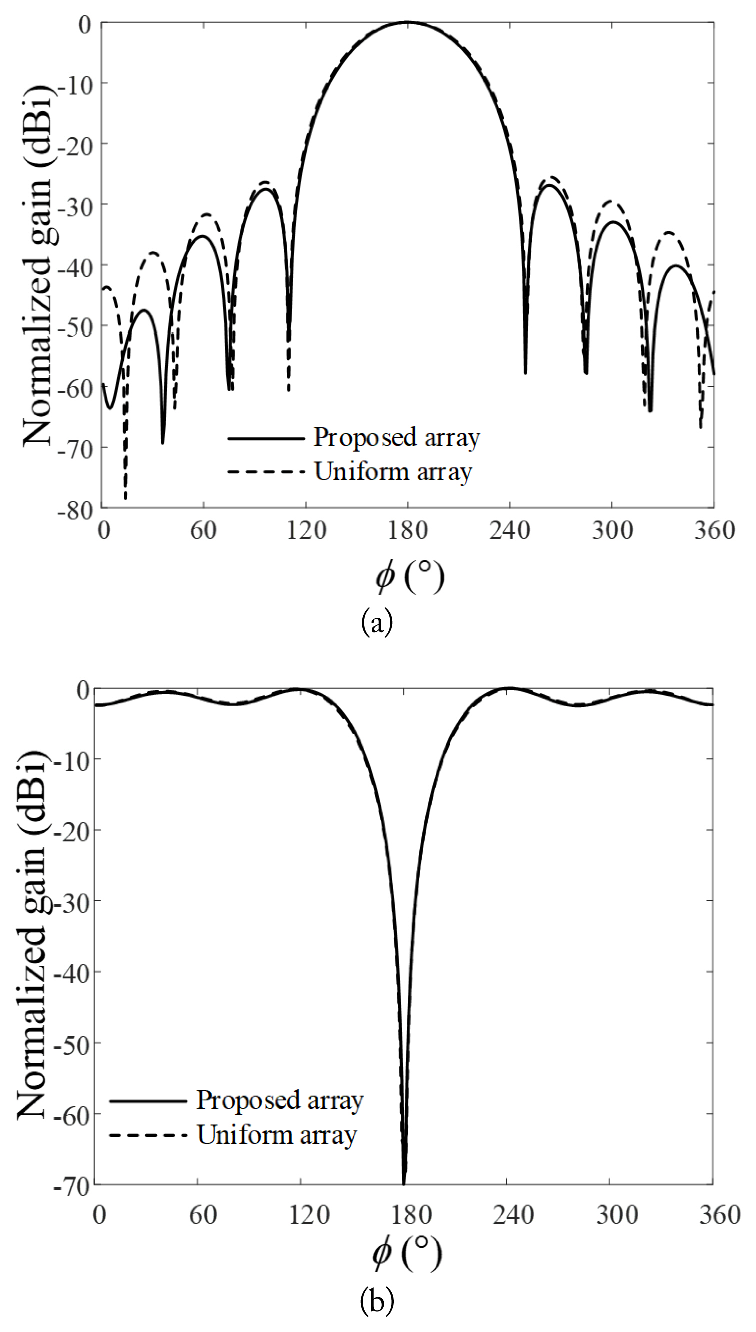
Fig. 6 shows the patterns of the reference and surveillance beams at a center frequency of 98 MHz in the FM band. The solid lines indicate the beam pattern of the proposed array, and the dashed lines represent the beam pattern of the UCA configuration. For the proposed array, the PSLR and FNBW are 13.3 dB and 139°, respectively, and the null depth and null width are 37.5 dB and 23°, respectively. The exact values of the PSLR, FNBW, null depth, and null width at all analysis frequencies are listed in Table 2. The results indicate that the average PSLR and null depth at three frequencies (88, 98, and 108 MHz) are greater than those in the UCA configuration by 0.7 dB and 0.7 dB, respectively.
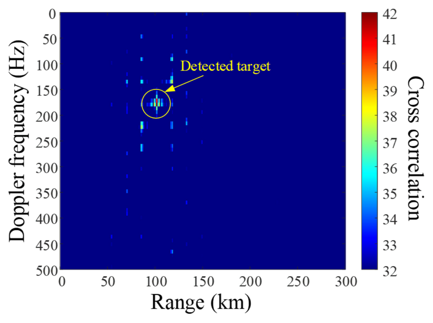
To verify the detection performance using the proposed array, an amplitude range–Doppler map is created as shown Fig. 7. In the given scenario, the distance between the PCL radar and the target is assumed to be 100 km, and the target’s velocity is assumed to be 551 m/s. The received reference and surveillance signals are used in the cross-correlation equation to obtain the amplitude range–Doppler map. The cross correlation χ can be calculated as
where τ is the signal delay between the received reference and surveillance signals, and fd is the Doppler frequency according to the target’s velocity. With a target velocity of 551 m/s, the actual Doppler frequency is 180 Hz. The value derived from the correlation equation is 179 Hz. The estimated range between the PCL radar and the target is 101.2 km, which is close to the scenario’s range of 100 km. These results demonstrate that the proposed non-uniform array for PCL systems can effectively detect targets.
IV. Conclusion
Non-uniform array configurations were investigated to maximize the beamforming performance of PCL systems. The proposed array consisted of eight dipole elements that are divided into two groups with distances of 0.41λ and 0.32λ from the array center, respectively. The individual dipole element had a bandwidth of 23 MHz (85 to 108 MHz, VSWR < 2), which showed suitable performance for PCL systems. The array antenna characteristics (PSLR, FNBW, null width, and null depth) were then investigated to derive the optimum array configuration. The results showed that the average PSLR and null depth of the proposed array at three frequencies (88, 98, and 108 MHz) were greater than those of the UCA configuration by 0.7 dB and 0.7 dB, respectively. Moreover, the proposed non-uniform array configuration had more suitable beam patterns compared with the conventional UCA. The target detection performance of the proposed array was tested in a certain scenario, and the target was detected with Doppler and range errors of 1 Hz and 1.2 km, respectively.