Design of Compact and Superdirective Metamaterial-Inspired Two- and Three-Elements Antenna Arrays
Article information
Abstract
This paper presents the development of a miniature antenna array in a small space in order to achieve superdirectivity for long-range communication. The proposed structures consist of a superdirective metamaterial-inspired array based on a capacitively loaded loop (CLL) driven by an electrically small monopole antenna. This elementary antenna is then used in two- and three-array configurations separated by a fixed interelement distance of 0.1λ to achieve a higher directivity and compact size (with λ the wavelength calculated at the operation frequency 1.850 GHz). The design of the elementary antenna, its simulated radiation performances, as well as those of the parasitic array are also reported. The results of the optimization of two- and three-antenna arrays are discussed. For this study, three corresponding prototypes were fabricated and tested. The measured impedance mismatch and radiation pattern results are presented and shown to be in good agreement with their simulated values. The maximum measured directivity is equal to 5.9 dBi and 4.75 dBi in the case of the two- and three- elements, respectively. The proposed antenna arrays can serve for the realization of point-to-point wireless links and can have a significant impact on compact and high-directive radiofrequency front-ends of a wireless system and for wireless power transfer applications.
I. Introduction
With the increasing demand for new radio technologies, such as wireless power transfer, low-power wireless communications, and Internet-of-Things, new miniaturized electrically small antennas (ESAs) have been designed [1]. In such antennas, high directivity and efficiency are highly required. However, decreasing the antenna’s size usually results in the deterioration of the antenna’s radiation properties, in addition to the reduction of the impedance bandwidth. To improve the directivity of a single radiating element, we can configure an array [2]. An antenna array is typically designed to minimize mutual coupling by spacing the radiating elements at least one-half wavelength apart. However, this increases the overall size of the antenna. The phenomenon of superdirectivity can be achieved by closely spacing the antennas and creating strong mutual coupling, resulting in a noticeable increase in array directivity. One of the emerging techniques to satisfy these new requirements of wireless application is to integrate the ESAs in array configurations to realize compact superdirective devices by keeping the coupling distance between two adjacent antennas less than a fraction of the wavelength [3]. Therefore, by decreasing the interelement distance to less than one-half wavelength to reduce the array size, we can increase the mutual coupling that results in the deterioration of the total array efficiency [2]. Recently, to minimize the mutual coupling between ESAs, a few techniques were developed comprising the array, such as the use of a special feeding network [3], decoupling circuits [4], parasitic loaded scatter [4], and short-printed monopoles [5], and parasitic radiating elements [6].
In particular, to increase the directivity, the use of parasitic radiating elements in arrays has emerged as an interesting solution to overcome the challenges of integrating ESAs in compact arrays. First, in [6], the authors proved that for a two-element antenna array, exciting only one element while keeping the other short-circuited is similar in terms of directivity to the case where both elements are excited. The next step was to design several two-element superdirective arrays with different configurations according to the parasitic element state: short-circuited [7], matched [8], open-circuited [9], or loaded [10] with a capacitance. By using a synthesis procedure based on the array factor [11, 12], two compact end-fire linear arrays with three elements have been optimized in terms of directivity or gain.
This paper investigates the design of two- and three-elements parasitic ESA arrays for directivity enhancement. The first part of the paper describes the design and simulated results of the elementary antennas [13, 14] as well as the two- and three-element antenna arrays. Then, the paper presents the measured performances of their prototypes in terms of input impedance mismatch, gain, directivity, and radiation efficiency.
II. Design and Simulation
1. Arrays’ Design
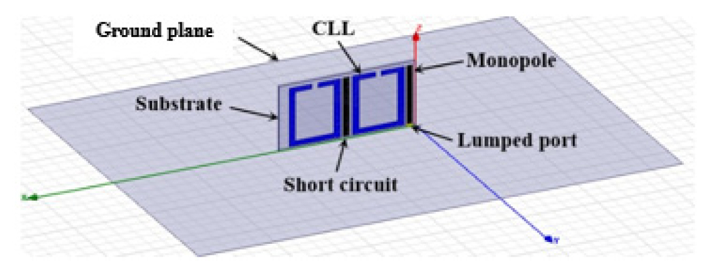
Arrays are designed using monopoles and CLLs printed on Rogers Duroid 5880 substrates with a thickness of 0.8 mm and relative permittivity ɛr of 2.2. The printed monopole and CLL element are placed perpendicular to a planar ground plane with surface area (100 mm × 100 mm) and thickness h of 2 mm, of where the monopole is excited, via a hole in the ground plane, with a feeding coaxial cable ended with a connector of impedance 50 Ω.
The length of the printed monopole (l = 26.5 mm) is fixed to have a resonating frequency (Fr = 1.85 GHz) within the GSM 1,800 band. Here, the CLL element is placed close to the monopole to act as a parasitic element to reduce the resonant frequency for compactness and improve the directivity. The parameters of the design are shown in Fig. 1.
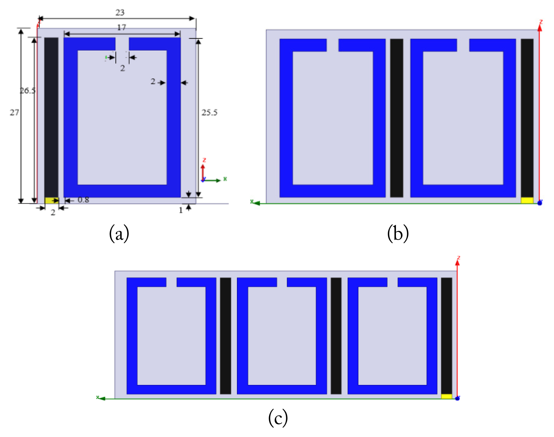
Elementary antenna geometry (unit in mm): (a) one element, (b) two elements, and (c) three elements.
We have designed both two- and three-element arrays by reproducing the unit cell along the x-direction as it is shown in Fig. 2(b). An element’s spacing between adjacent elements is fixed as 1 mm (λ/10). Only the elementary cell is excited through its monopole, whereas the other cells act as parasitic elements, and their monopoles are short-circuited with the ground plane.
2. Simulated Results
Simulations of the elementary structure as well as the two-elements and three-elements arrays were performed by using the 3D electromagnetic simulator ANSYS High-Frequency Structure Simulator (HFSS) v15 [15].
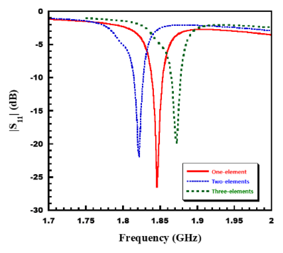
Fig. 3, presents the simulated impedance matching over the frequency band 1.7–2 GHz for the studied structures.
As shown in Fig. 3, the resonating frequencies of the elementary, two-element, and three-element antenna arrays are 1.85 GHz, 1.82 GHz, and 1.87 GHz, respectively, with good matching (|S11| < −20 dB). The frequency shift between resonant frequencies may be attributed to the presence of parasitic elements close to the monopole area.
For the radiation properties, Fig. 4 gives the 3D directivity patterns of the three studied structures at their resonant frequencies. It can be noticed that the maximum values of the total directivity are 5.07 dB, 7.21 dB, and 4.28 dB for the elementary antenna, two-elements, and three-elements arrays, respectively. Thus, we can deduce that the addition of the first unit cell increases the total directivity by more than 2 dB. However, the addition of the second unit cell to obtain a three-element array decreases the total directivity to 4.28 dB, which is lower than that the elementary antenna. This phenomenon can be explained by the concept of simulated surface currents distribution, as presented and discussed in [16].
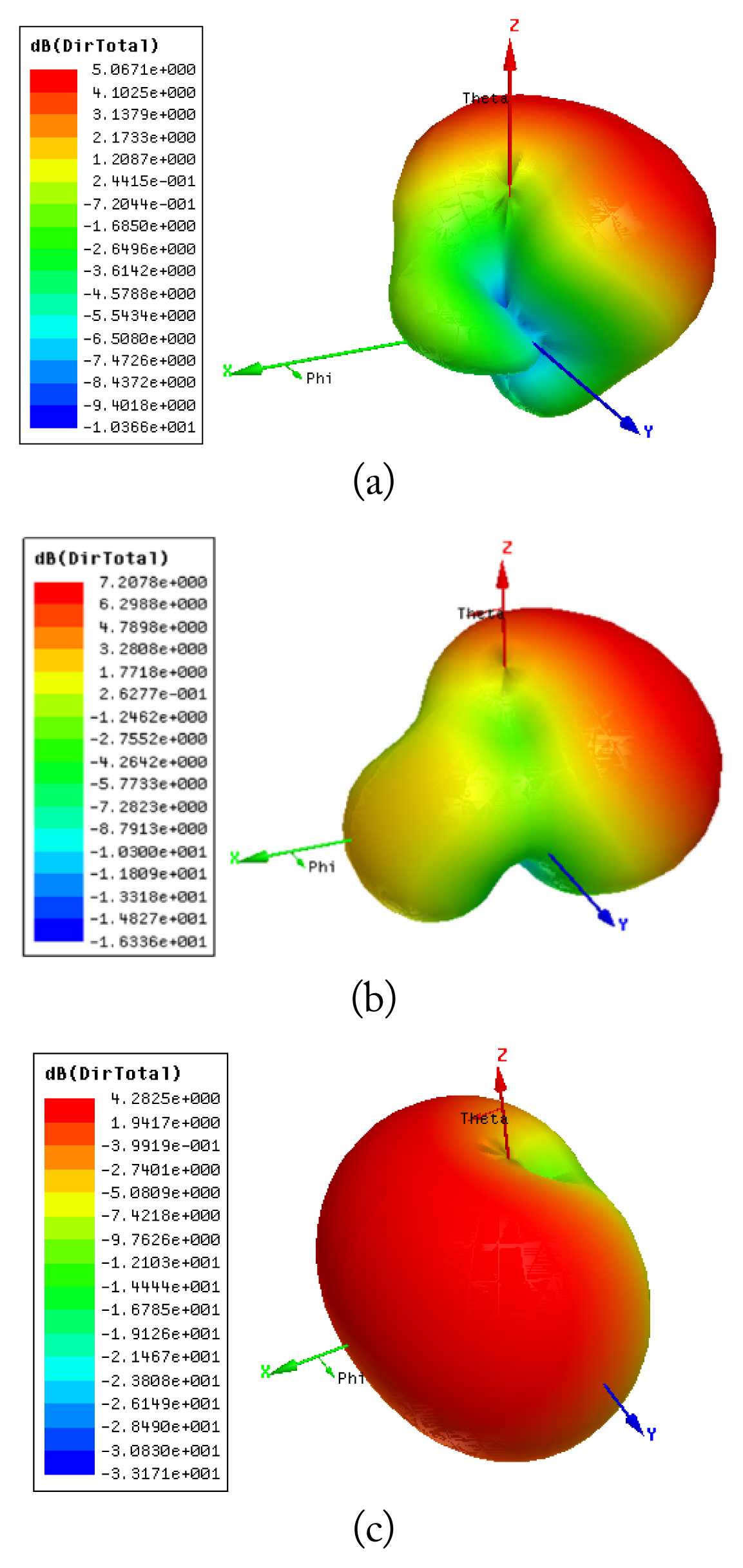
A 3D simulated total directivity radiation pattern corresponding to (a) one element, (b) two elements, and (c) three elements.
A 3D radiation pattern at the resonance frequency is shown in Fig. 4.
III. Experimental Results and Discussions
To validate the simulation results, prototypes of elementary antennas and two- and three-element array configurations were manufactured and measured. All the proposed arrays were placed orthogonally on a copper ground plane. Fig. 5 shows photographs of the prototypes.
To characterize these prototypes experimentally, their impedance mismatch at the frequencies between 1 and 3 GHz as well as their gain pattern at their resonant frequencies were measured. The network analyzer Agilent N5230A was used to measure the impedance mismatch, i.e., the |S11| values as a function of source frequency. The gain patterns were obtained in a “Satimo STARGATE 32” anechoic chamber. Figs. 6–9 illustrate the performance characteristics of three proposed antennas.

Input reflection coefficient magnitude measured and simulated for the studied antennas: (a) one element (b) two elements, and (c) three elements.
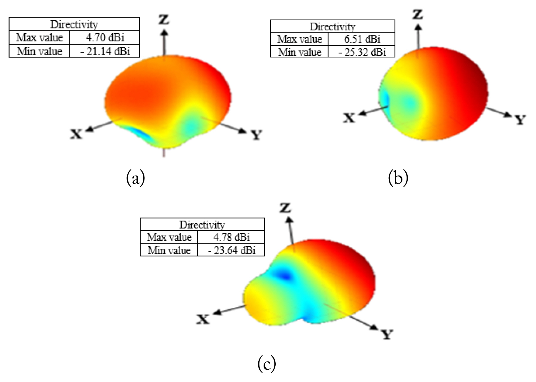
Measured results of the 3D directivity radiation pattern (unit in dBi): (a) one element, (b) two elements, and (c) three elements.
1. Impedance Mismatch
Fig. 6 shows the measured and simulated input impedance mismatch values for the three proposed antennas as a function of the excitation frequency. According to Fig. 6, the elementary antenna’s resonant frequency was 1.84 GHz with a matched bandwidth of 30 MHz between 1.815 GHz and 1.845 GHz. A very good agreement was found between the resonance frequency and its relevant simulation. In the case of the two-element array, the measured antenna resonance frequency was noted to be 1.83 GHz, which also agreed with that of the simulation. However, the measured resonance bandwidth was slightly larger due to the finite size of the ground plane. Finally, in the case of the three-element array, there is a marked discrepancy was noted between the measured resonance frequency (1.77 GHz) and the simulated one (1.79 GHz). This could be because the ground plane edge was very close to the second parasitic element. Perhaps, if the ground plane size had increased further, a closer agreement could have been obtained.
2. 3D Directivity
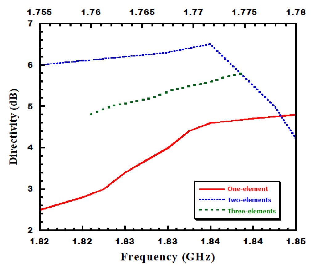
The measured 3D directivity for the three antennas is given in Fig. 7, in which Fig. 7(a) shows the 3D measured directivity of the elementary antenna prototype at 1.83 GHz. As predicted by simulation, the pattern is more directive along the negative x-axis at this frequency, with a maximum directivity of 4.7dB. Fig. 7(b) shows that the two-element array has a maximum directivity of 6.5 dB at the resonance frequency. Finally, Fig. 7(c) shows that the three-element array has a maximum directivity of 4.78 dB at resonance.
3. Directivity and Efficiency
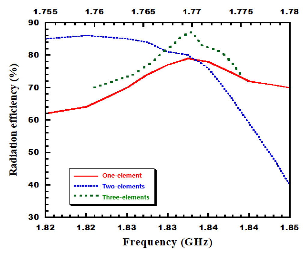
The measured performance characteristics of the three proposed antennas in terms of directivity and radiation efficiency are illustrated in Figs. 8 and 9. Table 1 summarizes the results of the three proposed models related to Figs. 8 and 9.
Table 2 presents the proposed antenna compared to the previously published work [17–20].
IV. Conclusion
This article describes the design of compact and superdirective metamaterial-inspired two- and three-element antenna arrays. The basic structure consists of a monopole associated with a CLL element. At the resonance frequency, it has a directivity of 5.06 dBi. Then, to achieve a higher directivity, a two-element compact parasitic array is configured and optimized using the elementary antenna. This array has a simulated directivity of 7.20 dBi. The prototype is fabricated to validate the simulation results, and good agreement has been observed between simulation and measurements in terms of impedance matching, directivity, and radiation patterns. Hence, the proposed antenna can be a promising candidate for wireless power transfer applications. Future work will explore the possibility of improving antenna efficiency and making these structures reconfigurable to control the direction of the radiation pattern.
Acknowledgments
The authors are thankful to Deanship of Scientific Research, King Abdulaziz University for providing financial (Grant No. RG-14-135-43).
References
Biography

Saber Dakhli is an assistant professor of Electrical Engineering at the Department of Telecommunications of the Higher Institute of Information and Communication Technologies (ISTIC), University of Carthage. He obtained his Ph.D. in 2015 from the University of Rennes 1. Since 2010 to 2015, he was with the Rennes Institute of Electronics and Telecommunications (IETR), France. Since 2012 he has been with the Laboratory Innov’Com at Supcom, Tunisia. From 2019 to 2021 he was a lecturer at the Military Academy of Foundok Jedid in Tunisia. Actually, he is a research engineer in the Rennes Institute of Electronics and Telecommunications (IETR), France. His main research activities concern metamaterials, antennas, RF filters, and RADAR systems.

Jean Marie Floc’h received his Ph.D. in Electronics in 1992 from the INSA Rennes, France. He joined the IETR institute as Research Engineer where he supervised master’s and Ph.D. students, in addition to the execution of many research projects with collaboration of the industry. His research interests concern the design of different type of antennas for wireless applications.

Mohammed Aseeri (M’05–SM’08) received his B.Sc. degree in electrical engineering (Communications) from King Abdulaziz University (KAU), College of Engineering and Computing Science, Jeddah, Saudi Arabia, in 1995 and his M.Sc. degree in electrical engineering (Electronics and Communications) from same University KAU, in 1998, and his Ph.D. degree in electronics from University of Kent, Canterbury, England in 2003. Currently he is working at King Abdulaziz City for Science and Technology (KACST), Riyadh, Saudi Arabia, as full professor at National Centre for Telecommunications and Defense Systems Technologies (TDST). Since 2017, he worked as a Co-PI at joint center of Excellence for Microwave Sensor Technology (CMST) between University of Michigan, Ann Arbor, USA and KACST. In 2022, he was appointed as a Vice Chairman of the board of directors of the Association for Scientific Research and Innovation (ASRI), Riyadh, Saudi Arabia. His current research interests are the mm-wave and terahertz circuit design, such as FMCW radars for imaging, spectroscopy, metrology, and communication systems, as well as on wireless sensor networks (WSN), security networks, e-strategic management, and security planning.

Ameni Mersani received a degree in electronics, computer and information science from the University Tunis El Manar, Tunisia, in 2009 and the master’s degree in electronics from the Faculty of Science of Tunis, Tunisia, in 2012. She received a Ph.D. in Engineering Sciences (Electronics) from the University of Tunis El Manar, 2018. From September 2018, she has been working a research assistant in ISET’COM (Department of Telecommunication). From December 2019, she has been a post-doctoral researcher with King Abdulaziz University, Saudi Arabia. Her research mainly focuses on the development of the design of wearable antennas for wireless applications and metamaterial, dipole antenna and infrared energy harvesting.

Hatem Rmili received the B.S. degree in general physics from the Science Faculty of Monastir, Tunisia, in 1995, and the DEA diploma from the Science Faculty of Tunis, Tunisia, in quantum mechanics, in 1999. He received the Ph.D. degree in physics (electronics) from both the University of Tunis, Tunisia, and the University of Bordeaux 1, France, in 2004. From December 2004 to March 2005, he was working as a research assistant in the PIOM Laboratory at the University of Bordeaux 1. From March 2005 to March 2007, he was a post-doctoral fellow at the Rennes Institute of Electronics and Telecommunications, France. From March to September 2007, he worked as a post-doctoral fellow at the ESEO engineering school, Angers, France. From September 2007 to August 2012, he worked as an associate professor with the Mahdia Institute of Applied Science and Technology (ISSAT), Department of Electronics and Telecommunications, Tunisia. Actually, he is full professor in the Electrical and Computer Engineering Department, Faculty of Engineering, King Abdulaziz University, Jeddah, Saudi Arabia. Professor Rmili’s research interests concern applied electromagnetic applications involving antennas, metamaterials, and metasurfaces. The main targeted applications are reconfigurable antennas for multistandard wireless communications systems, security of chipless RFID systems with fractal tags, terahertz photoconductive antennas for infra-red energy harvesting, UWB nano rectennas for collection of solar energy, phase shifters for low-cost 5G communication systems, and microwave absorbing materials for stealth technologies.
