Non-Uniform Metasurface-Integrated Circularly Polarized End-Fire Dipole Array Antenna
Article information
Abstract
This paper presents a high-gain wideband circularly polarized antenna composed of an end-fire dipole array antenna integrated with a metasurface. The antenna consists of a two-layer cascaded non-uniform metasurface made up of 4 × 4 circular patches with cross-slots of unequal lengths placed above an end-fire dipole array antenna with an air gap between the structures. The end-fire dipole array antenna comprises four equally spaced dipole elements, and each dipole is connected to a parallel stripline printed on the front and back sides of the substrate. The metasurface, which is made up of a circular patch with 2 × 2 center patches that have a different radius than the outer patches, and the cross-slots of unequal lengths are used for the polarization conversion of a linearly polarized wave to a circularly polarized wave. The measured reflection coefficients for |S11| < −10 dB yielded an impedance bandwidth of 25.6–31.8 GHz (21.5%), a 3-dB axial ratio (AR) bandwidth of 26.1–30.5 GHz (15.5%), a 3-dB gain bandwidth of 26.0–31.1 GHz (17.4%) with a peak gain of 11.0 dBic, and a radiation efficiency of more than 80% in the axial ratio bandwidth.
I. Introduction
The tremendous increase in the demand for high data rates has led to the deployment of fifth-generation (5G) new radio (NR) technologies, owing to their high throughput of many gigabits per second (Gb/s). The 5G NR systems use millimeter-wave frequency allocation bands ranging from 24 GHz to 100 GHz [1–3]. The millimeter-wave spectrum can provide the capacity required for future wireless data applications because of its wide available bandwidth, which satisfies the demand for ubiquitous, super-fast connectivity and seamless service delivery. Most countries are considering or have chosen the 26/28 GHz band for 5G NR technologies [3, 4]. To take advantage of the large bandwidth in the millimeter-wave frequency band, a significant increase in system gain is required to compensate for the high propagation and atmospheric losses intrinsic in this spectrum. Recently, attention has been directed to the design of high-gain antennas to overcome problems in millimeter-wave bands [5–9]. Several works have been carried out to design high-gain antennas for millimeter-wave frequency bands, such as incorporating metamaterial unit cells in front of end-fire radiation antennas [10–13]. Moreover, the radiated beam is focused on achieving high gain and wideband characteristics by placing a dielectric lens on a radiator at millimeter-wave frequencies; however, they have low radiation efficiencies due to losses in the thick dielectric material [14]. Array antennas provide a high gain to increase signal strength but suffer from power losses in complex power divider networks [15, 16]. Moreover, the major drawback of the aforementioned designs [10–16] is that they produce only linearly polarized (LP) waves. Compared with LP antennas, circularly polarized (CP) antennas are often preferred due to their superior ability to mitigate the polarization mismatch between the transmitting and receiving antennas and to reduce multipath interference or fading [17]. A convenient way to generate CP waves is to combine LP waves from LP antennas with linear-to-circular polarization converters. Unlike conventional CP antennas, LP antennas and circular polarization converters can be designed separately without a complicated feeding network. Various types of LP sources have been utilized in conjunction with linear-to-circular polarization converters to generate CP waves. Prominent LP sources include slot antennas [18, 19], horn antennas [20], and dipole antennas [21–24].
A metasurface, a two-dimensional equivalent of a metamaterial, has attracted considerable attention and has been applied to enhance antenna performance because of its unique ability to manipulate electromagnetic waves that are unusual or difficult to obtain in nature [25–27]. At present, many planar two-dimensional metamaterial (metasurface) polarizers have been designed to realize CP waves from LP waves [28–33]. Only a few studies have been proposed to integrate linear-to-circular polarization converters with end-fire radiation antennas for millimeter-wave frequency bands. In [21], the authors designed a dual-band dipole antenna to operate at millimeter-wave frequencies as the LP source and incorporated it with a dual-band linear-to-circular polarization converter to realize CP waves. However, they achieved impedance bandwidths of only 9.05% (29.0–31.75 GHz) and 22.22% (20–25 GHz) in the lower and upper frequency bands, respectively. It also exhibited narrow CP bandwidths of 7.8% (20.10–21.25 GHz) and 6.57% (29.4–31.4 GHz) in the lower and upper frequency bands, respectively. In addition, a major characteristic, such as the gain of the antenna is low in the above designs. However, low-gain antennas are not suitable for millimeter-wave bands. The series-fed dipole array is a well-known technique for increasing the gain of an antenna. Angled dipole antennas are smaller and have less mutual coupling than antennas with straight dipoles [6, 8]. The radiation pattern characteristics, such as the gain and front-to-back ratio of the angled dipole antennas, are also better than those of the straight dipoles. Single-angle printed dipole antennas produce low-gain characteristics [34, 35]. By increasing the number of elements to form a series-fed angled dipole array [5], the gain of the antenna can be increased significantly, which makes the antenna suitable for use in millimeter-wave frequency bands. The series-fed angled printed dipole array antenna produces LP waves. We exploit the unique advantages of the high gain and good radiation of the series-fed angled dipole array to incorporate it with a linear-to-circular polarization converter to convert the LP wave into a CP wave.
In this study, we present a high-gain, wideband CP series-fed angled dipole array antenna that uses a non-uniform metasurface [36–38] made up of a circular patch with cross-slots of unequal lengths for the polarization conversion of an LP wave to a CP wave. The antenna consists of two cascaded metasurfaces made up of 4 × 4 circular patches with cross-slots of unequal lengths placed above the series-fed angled dipole array LP source antenna in the end-fire direction with an air gap. The use of non-uniform metasurface patches results in a considerable improvement in the gain and axial ratio (AR) bandwidth compared with uniform metasurface patches [38]. The resulting antenna shows good performance characteristics with a wide impedance bandwidth of 25.6–31.8 GHz (21.5%), a wide AR bandwidth of 26.1–30.5 GHz (15.5%), a 3-dB gain bandwidth of 26.0–31.1 GHz (17.4%), a peak gain of 11.0 dBic, and a high radiation efficiency greater than 80% in the AR bandwidth.
II. Antenna Geometry and Design
The geometry of the proposed antenna is shown in Fig. 1. The antenna consists of a four-element angled printed dipole array with a cascaded two-layer CP metasurface patch placed in its end-fire direction with an air gap. A Rogers RT/Duroid 4003 substrate with a dielectric constant of ɛr = 3.38, loss tangent of tanδ = 0.0027, and thickness of hs = 0.254 mm is used for the four-element angled printed dipole array. As shown in Fig. 1(a), each dipole arm is bent at an angle of 45° to the ground plane side. Each arm of the dipole is printed on both sides of the substrate, as shown in Fig. 1(c). The spacing between dipoles is designed to be uniform, and the dipole length is reduced by ΔLd, starting from the dipole element nearest to the ground plane. The four-element angled dipole arrays are connected in series using a parallel stripline. Electromagnetic power supplied to the microstrip line is transferred to the dipole through a parallel stripline printed on the front and back sides of the substrate. The input impedance of the parallel stripline is matched to a 50-Ω microstrip feedline using a quarter wavelength transformer of length Lt and width Wt.
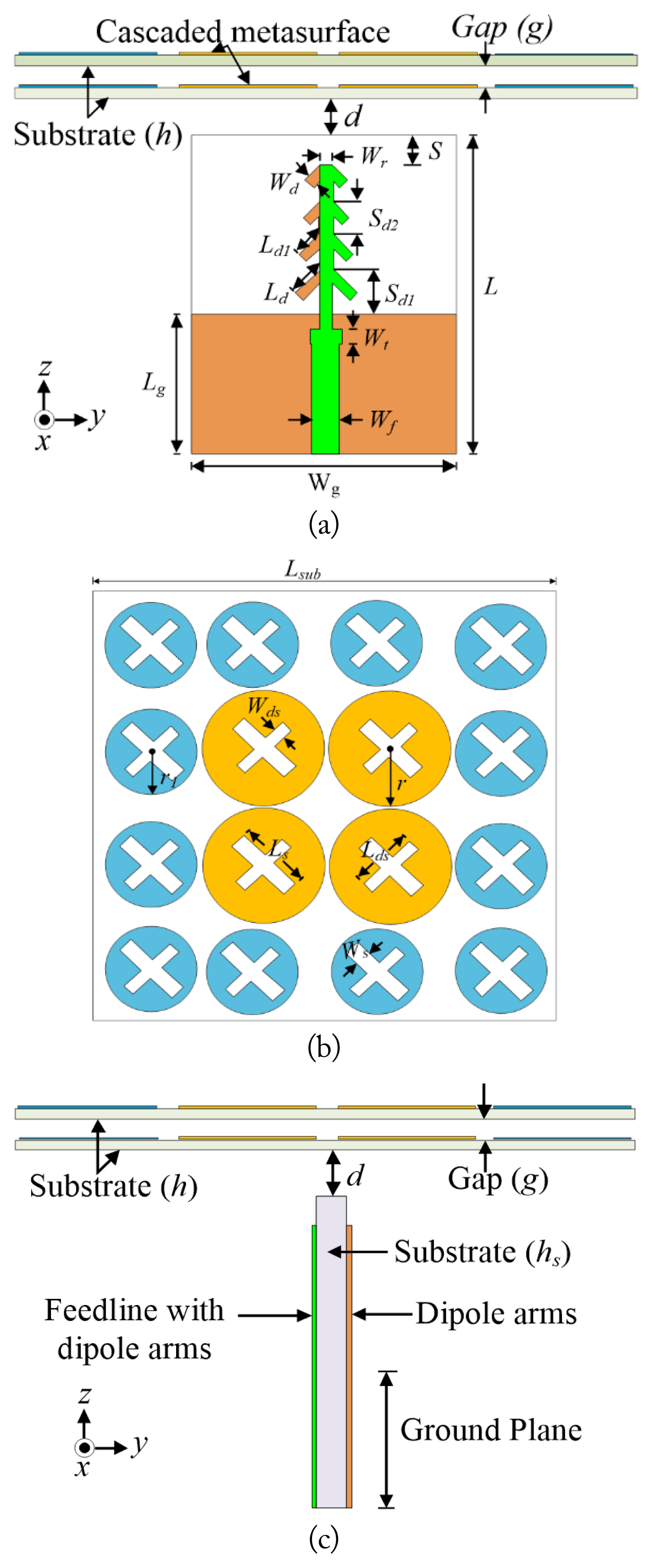
(a) Four-element angle printed dipole array with a cascaded two-layer CP metasurface, (b) 4 × 4 cross-slot metasurface patch, and (c) side view of the four-element angle printed dipole array.
The double-cascaded linear-to-circular polarization conversion metasurface is placed above the source antenna with air gap d. The two layers of the cascaded metasurface are separated from each other by air gap g. An RO4003 (ɛr = 3.38, tanδ = 0.0027) dielectric substrate with a thickness of h = 0.508 mm is used for both metasurfaces. As shown in Fig. 1(b), the nonuniform metasurface is made up of a 4 × 4 array lattice of circular patches with periodicity P. The non-uniform metasurface patches are composed of a center 2 × 2 patch with radius r and an outer patch with radius r1. A circular patch with slots of unequal lengths is used to produce CP radiation [39–43]. The cross-slots with lengths Ls and Lds are crossed orthogonally at the center of each slot, which is the center of the circular patch [39].
The antenna was optimized using the ANSYS high-frequency structure simulator to obtain high gain, good impedance matching, and wide AR bandwidth. The optimized design parameters are as follows: P = 7.6 mm, r = 3.7 mm, r1 = 3.1 mm, L = 23 mm, Wr = 0.2 mm, Wf = 0.7 mm, Lt = 3 mm, Wt = 0.8 mm, Wd = 0.3 mm, d = 4 mm, g = 1.5 mm, Sd1 = 3.2 mm, Sd2 = 1.2 mm, Ls = 4.8 mm, Lds = 4 mm, Ws = 1mm, Wds = 1 mm, Ld = 2.2 mm, Lsub = 30.7 mm, and h = 0.508 mm.
The design guidance and methodology of the proposed antenna are as follows:
The four-element series-fed printed angled dipole array antenna is designed to operate at the desired millimeter-wave frequency. The dipoles are connected in series using a parallel stripline. The quarter wavelength transformer is used to match the impedance of the parallel stripline to that of the 50-Ω microstrip feedline. Each dipole has a uniformly reduced length, and there is identical spacing between them.
A single-layer metasurface made up of 4 × 4 circular patches with cross-slots having unequal lengths (Ls, Lds) for linear-to-circular polarization conversion is designed and placed in the end-fire direction of the series-fed angled dipole array with air gap d.
An additional layer is added to the metasurface to form a cascaded two-layer CP metasurface with air gap g between the two metasurface layers.
The configuration of the metasurface patches in the metasurface layers is changed to non-uniform metasurface patches consisting of 2 × 2 inner center patches with radius r and outer patches with radius r1.
The CP antenna with a wide bandwidth and high gain is obtained by carefully adjusting the parameters of the cascaded two-layer metasurfaces and the series-fed printed angled dipole array.
III. Operation Mechanism
To better understand the operational mechanism of the proposed antenna, first, the four-element series-fed printed angled dipole array antenna is simulated without the metasurface (Antenna I). Second, a single-layer metasurface made up of 4 × 4 circular patches with cross-slots of unequal lengths is placed above Antenna I with air gap d (Antenna II). Third, an additional layer of uniform 4 × 4 metasurface circular patches with cross-slots of unequal lengths is placed above Antenna II with air gap g (Antenna III). Finally, the uniform metasurface 4 × 4 circular patches in Antenna III are replaced with nonuniform 4 × 4 metasurface circular patches consisting of inner 2 × 2 center patches of radius r and outer patches of radius r1 (Antenna IV). The characteristics of Antennas I, II, and III are then compared with those of the proposed antenna (Antenna IV). The simulated results for the |S11|, gain, and AR for Antennas I, II, III, and IV are shown in Fig. 2. Antenna I achieves an impedance bandwidth of 24.7% at a range of 25.5–32.7 GHz (Fig. 2(a)), a peak gain of 9.8 dBi (Fig. 2(b)), and an AR > 20 dB (Fig. 2(c)). Antenna II (Antenna I + a single-layer metasurface) achieves an impedance bandwidth of 20.5%, which covers 26.1–32.2 GHz (Fig. 2(a)), a peak gain of 9.4 dBic (Fig. 2(b)), and an AR bandwidth of 4.2% at a range of 23.1–24.0 GHz (Fig. 2(c)). Antenna III (Antenna I + a uniform two-layer cascaded metasurface) achieves an impedance bandwidth of 20.7% at a range of 25.9–31.85 GHz (Fig. 2(a)), a peak gain of 10 dBic (Fig. 2(b)), and an AR bandwidth of 7.4% at a range of 27.1–29.2 GHz (Fig. 2(c)). Antenna IV (Antenna I + a nonuniform two-layer cascaded metasurface) has an impedance bandwidth of 20.5%, which covers 25.9–31.8 GHz (Fig. 2(a)), a peak gain of 11.1 dBic (Fig. 2(b)), and an AR bandwidth of 17.4% at a range of 26.1–31.1 GHz (Fig. 2(c)). Antenna I shows good gain characteristics in the end-fire direction (+z-axis) and produces LP waves. The metasurface, made up of a nonuniform circular patch with cross-slots of unequal lengths, is used to convert the LP wave from the source antenna (Antenna I) to CP waves. The resonant frequency of the circular microstrip patch decreases as the coupling slot length increases. Thus, by adjusting the lengths (Ls, Lds) of the two arms of the cross-slot so that they are different and both arms have a proper length ratio (Ls/Lds), the fundamental frequency of the circular microstrip patch can be split into two near-degenerate resonant modes with near-equal amplitudes and a 90° phase difference to produce CP waves. The unit cell analysis of the cross-slot-shaped metasurface is detailed in [43]. Thus, by placing the single-layer metasurface made up of 4 × 4 circular patches with cross-slots of unequal lengths in the end-fire direction of Antenna I, the LP wave from the source antenna is converted into a CP wave. This can be achieved by adjusting the arms of the cross-slot so that the reactance of the metasurface can be controlled for orthogonal electric fields with two near-degenerate resonant modes, near-equal amplitudes, and a 90° phase difference. However, Antenna II shows lower gain characteristics and a narrower AR bandwidth than Antennas III and IV, as shown in Fig. 2(b) and 2(c), respectively. Antenna IV shows improved gain and AR bandwidth performance characteristics compared with Antennas II and III due to the enhanced electromagnetic wave transmission obtained by introducing an additional metasurface layer to Antenna III. Finally, the parameters of the cascaded two-layer non-uniform metasurface are adjusted to achieve a near-equal amplitude and a 90° phase difference so that wideband CP radiation is obtained.
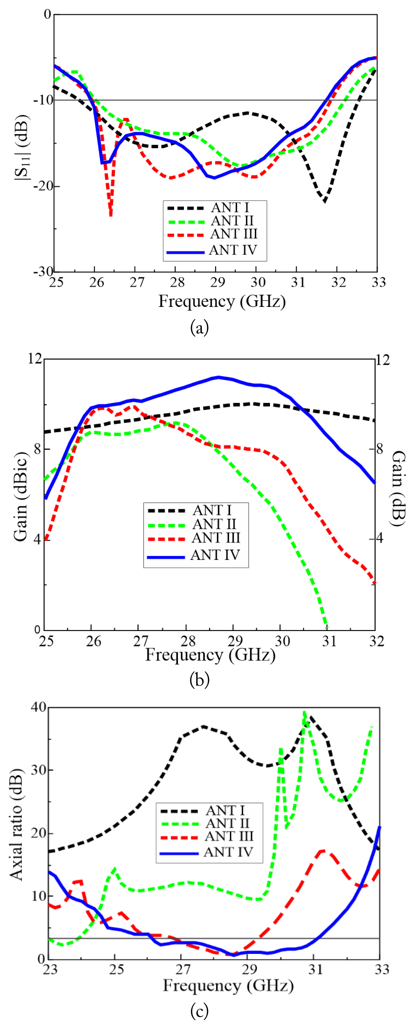
(a) Reflection coefficient, (b) gain, and (c) axial ratio of Antennas I, II, III, and IV.
IV. Antenna Characteristics
The effects of essential antenna parameters were investigated to understand their influence on antenna performance. Specifically, crucial antenna parameters, such as the air gap between the dipole array antenna and the cascaded metasurface (d), the gap between the two metasurface layers (g), metasurface substrate thickness (h), cross-slot width 1 (Wds), cross-slot width 2 (Ws), cross-slot length (Ls), inner circular patch size (r), and outer circular patch size (r1), were examined. The effects of these parameters on the reflection coefficient, AR, and gain were examined. During each study, the response of the antenna was determined when only one parameter was swept while the others were fixed.
The effect of varying the air gap between the dipole array antenna and the cascaded metasurface (d) on the reflection coefficient, gain, and AR is shown in Fig. 3(a), 3(b), and 3(c), respectively. The air gap (d) increases from 4 mm to 14 mm, and the resonant frequency shifts to the lower frequencies (Fig. 3(a)). This is due to the equivalent dielectric constant of multiple dielectric layers being proportional to the thickness of each layer.
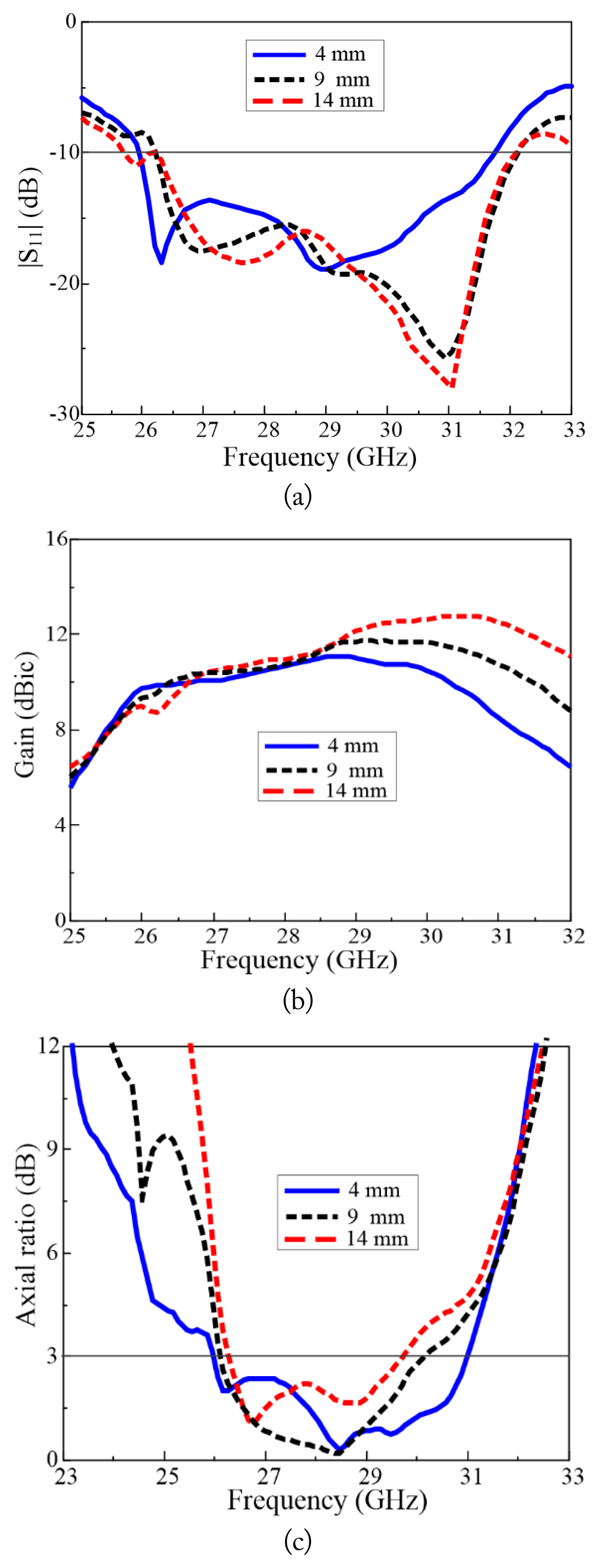
Effect of the air gap (d): (a) reflection coefficient, (b) gain, and (c) axial ratio.
An increase in the air gap (d) from 4 mm to 14 mm leads to an increase in gain (Fig. 3(b)). An increase in the air gap (d) from 4 mm to 14 mm degrades AR performance (Fig. 3(c)). The effect of varying the gap between the two metasurface layers (g) on impedance performance is shown in Fig. 3(c). The effect of varying the gap between the two metasurface layers (g) on impedance, gain, and AR is shown in Figs. 4(a), (b), and (c), respectively. As the gap between the two metasurface layers (g) increases from 1.5 mm to 3.5 mm, the resonant frequency shifts to the lower frequency. An increase in the gap between the two metasurface layers (g) leads to a decrease in the gain (Fig. 4(b)). Moreover, as the gap between the two metasurface layers (g) increases, and the AR performance deteriorates (Fig. 4(c)). The effect of varying the metasurface substrate thickness (h) on the reflection coefficient, gain, and AR is shown in Fig. 5(a), 5(b), and 5(c), respectively. Increasing h from 0.508 mm (20 mils) to 1.524 mm (60 mils) shifts the resonant frequency to lower frequencies (Fig. 5(a)). In addition, increasing h leads to a shift in the gain bandwidth toward the lower frequencies (Fig. 5(b)). An increase in h also leads to a shift in the AR bandwidth to lower frequencies (Fig. 5(c)). The effect of varying the cross-slot width 1 (Wds) on the reflection coefficient, gain, and AR is shown in Fig. 6(a), 6(b), and 6(c), respectively. When Wds increases from 0.5 mm to 1.3 mm, a shift occurs in the resonant frequency to the lower frequencies (Fig. 6(a)). As Wds increases, the gain slightly decreases in the lower frequencies (Fig. 6(b)). Wds has a significant effect on the AR values (Fig. 6(c)). As Wds decreases from 1.3 mm to 0.9 mm, the AR decreases, which greatly expands the AR bandwidth. However, a further decrease in Wds to 0.5 mm leads to a decrease in the AR bandwidth. The effect of varying the cross-slot width 2 (Ws) on the reflection coefficient, gain, and AR is shown in Fig. 7(a), 7(b), and 7(c), respectively. An increase in Ws from 0.5 mm to 1.5 mm leads to a shift in the resonant frequency to the lower frequencies (Fig. 7(a)), a decrease in the gain (Fig. 7(b)), and a downward frequency shift in the AR bandwidth (Fig. 7(c)). The effect of the cross-slot length (Ls) on the impedance, gain, and AR is illustrated in Fig. 8(a), 8(b), and 8(c), respectively. An increase in Ls from 4.1 mm to 5.9 mm leads to a shift in the resonant frequency toward the lower frequencies. An increase in Ls from 4.1 mm to 4.9 mm leads to an increase in the gain (Fig. 8(b)). As Ls increases further, the gain decreases. As shown in Fig. 8(c), at Ls = 4.1 mm, Ls = Lds; thus, no CP wave is produced because Lds has a length equal to that of Ls. This makes it impossible to obtain near-equal amplitudes and the 90° phase difference that arises from unequal cross-slot lengths. With a further increase in Ls, the AR performance deteriorates. The effect of the inner circular patch size (r) on the impedance, gain, and AR is shown in Fig. 9(a), 9(b), and 9(c), respectively. As r decreases from 3.7 mm to 3.1 mm, impedance matching improves, and there is no shift in the resonant frequency (Fig. 9(a)). An increase in r from 3.1 mm to 3.7 mm leads to an increase in the gain (Fig. 9(b)) and considerably improved AR performance (Fig. 9(c)). The effect of the outer circular patch size (r1) on the impedance, gain, and AR is shown in Fig. 10(a), 10(b), and 10(c), respectively. An increase in r1 brings no significant change to the reflection coefficient (Fig. 10(a)). As r1 increases from 3.1 mm to 3.7 mm, the gain decreases (Fig. 10(b)). The AR bandwidth shifts downward as r1 increases from 3.1 mm to 3.4 mm (Fig. 10(c)). With a further increase in r1, the AR performance deteriorates.
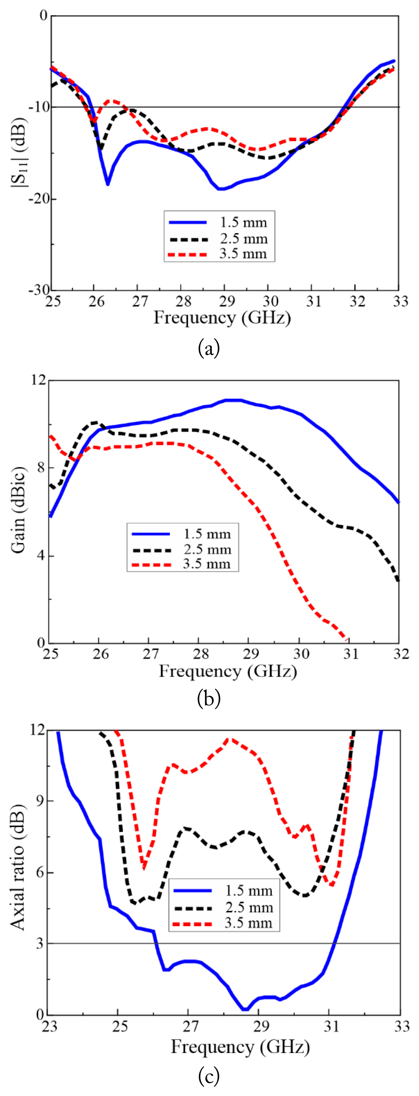
Effect of the gap between two metasurfaces (g): (a) reflection coefficient, (b) gain, and (c) axial ratio.
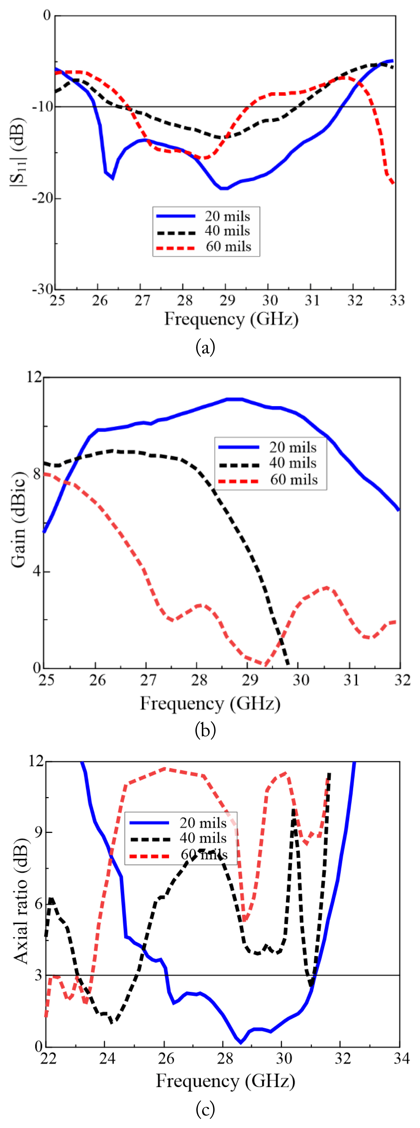
Effect of metasurface substrate thickness (h): (a) reflection coefficient, (b) gain, and (c) axial ratio.
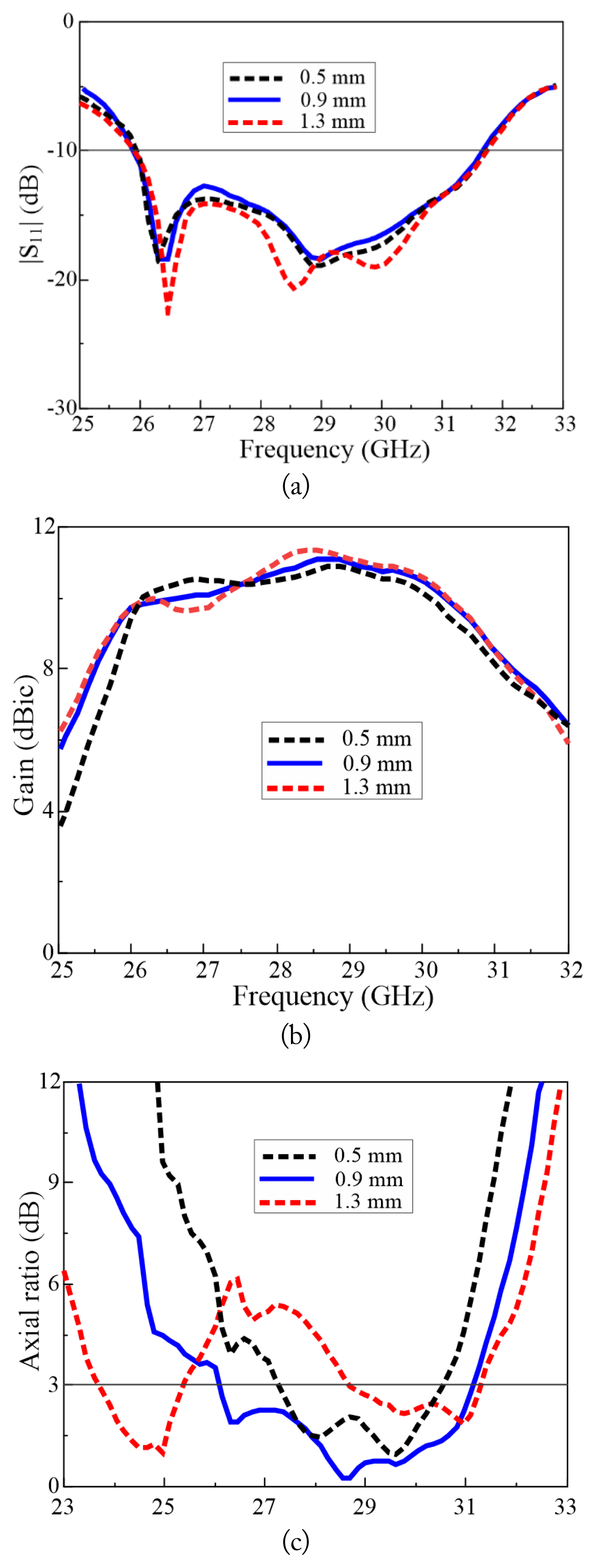
Effect of cross-slot width 1 (Wds): (a) reflection coefficient, (b) gain, and (c) axial ratio.
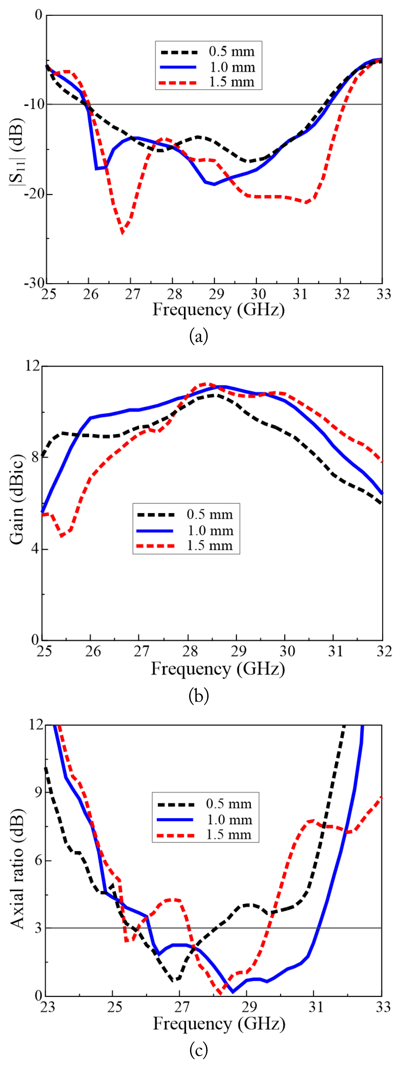
Effect of cross-slot width 2 (Ws): (a) reflection coefficient, (b) gain, and (c) axial ratio.
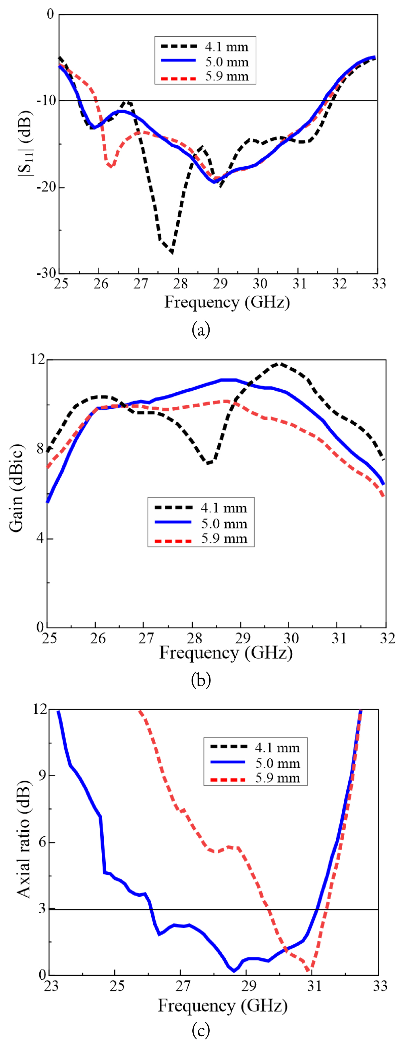
Effect of cross-slot length (Ls): (a) reflection coefficient, (b) gain, and (c) axial ratio.

Effect of the inner patch size (r): (a) reflection coefficient, (b) gain, and (c) axial ratio.
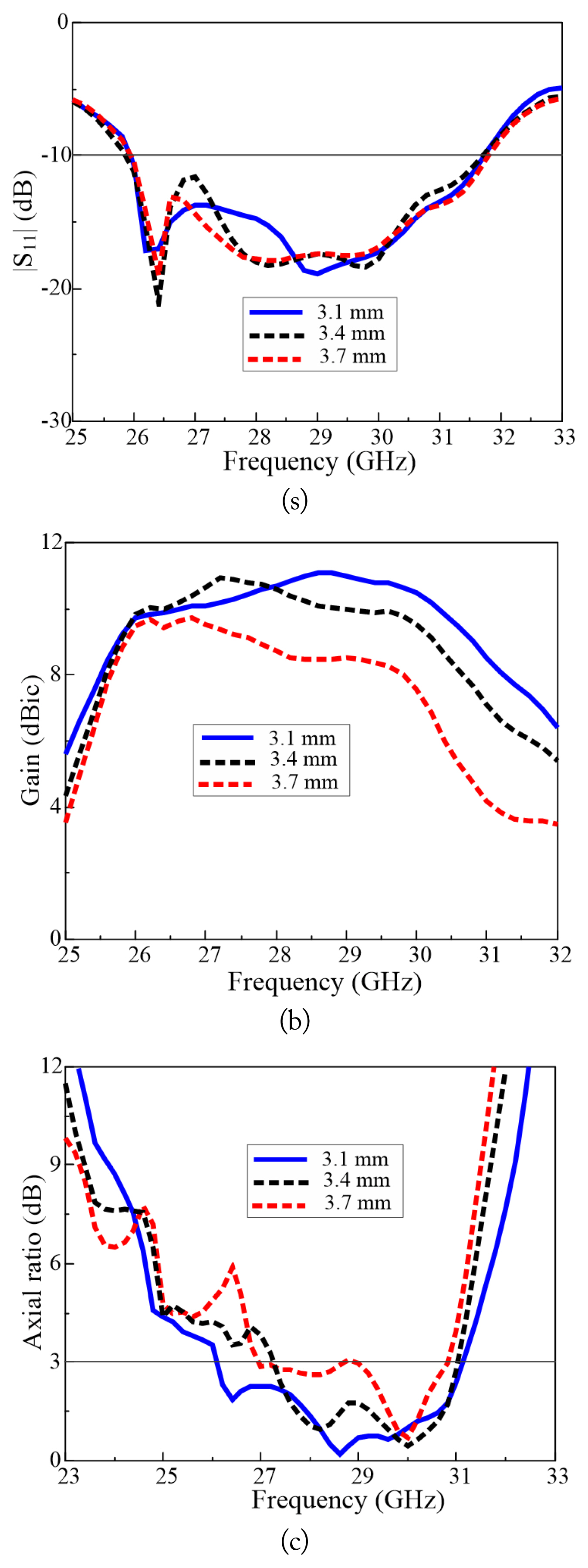
Effect of the outer patch size (r1): (a) reflection coefficient, (b) gain, and (c) axial ratio.
The simulated gain and measured radiation patterns of the antenna are presented in Fig. 11. The antenna exhibits stable gain characteristics, with a peak gain of 11.0 dBic. The radiation patterns in the xz-plane and yz-plane at 27.5, 28.5, and 29.5 GHz are presented in Fig. 11(a), 11(b), and 11(c), respectively. The gain at 27.5 GHz was 9.9 dBic, with a sidelobe level (SLL) of −5 dB for the xz-plane and 1 dB for the yz-plane. At 28.5 GHz, a peak gain of 11.0 dBic was obtained with an xz-plane SLL of −6 dB and a yz-plane SLL of 2 dB. The gain at 29.5 GHz was 9.5 dBic, with SLLs of −5 dB and 4 dB for the xz-and yz-planes, respectively. The backward radiation shown in Fig. 11 is the result of reflection from the metasurface layer. These reflections are responsible for the deterioration of the antenna’s front-to-back ratio [44].

Simulated and measured radiation patterns of the antenna at (a) 27.5 GHz, (b) 28.5 GHz, and (c) 29.5 GHz.
V. Experimental Results
To verify our design concept, the proposed antenna was fabricated and measured. The fabricated prototype sample is presented in Fig. 12. To fortify the antenna and make it easy to measure, a slab was introduced, and the substrate of the metasurface and that of the dipole array were extended and fitted into the slab. The Agilent N5230A network analyzer and a 3.5-mm coaxial calibration standard GCS35M were employed for the S-parameter measurements. Far-field measurements were conducted at the RFID/USN Center, Incheon, Republic of Korea. A full anechoic chamber and an Agilent E8362B network analyzer were used for the radiation pattern measurements. The proposed high-gain wideband CP antenna was used for reception, and a standard wideband horn antenna was used for transmission. A transmission distance of 10 m was established between them. The proposed antenna was rotated from −180° to +180° at 3°/s and a 1° scan angle, while the position of the horn antenna was left unchanged. Overall, the proposed antenna achieved good agreement between the simulated and measured data. Fig. 13 shows a comparison between the measured and simulated reflection coefficients for the fabricated antenna. The measured impedance bandwidth for |S11| < −10 dB was 25.6–31.8 GHz (21.5%), which is in good agreement with the simulated impedance bandwidth of 25.9–31.8 GHz (20.5%). Fig. 14 shows the simulated and measured AR bandwidths of the proposed antenna. The simulated AR bandwidth is 26.1–31.1 GHz (17.1%), and the measured AR bandwidth is 26.1–30.5 GHz (15.5%). Fig. 15 illustrates the simulated and measured gain of the proposed antenna. The antenna shows a stable gain characteristic of 8–11 dBic for both the measured and simulated gain of the antenna. Fig. 11 shows the simulated and measured radiation patterns. The radiation patterns at 27.5, 28.5, and 29.5 GHz do not change much for the xz- and yz-planes.

Fabricated prototype of the antenna: (a) top view (b) side view, and (c) 3D-view.
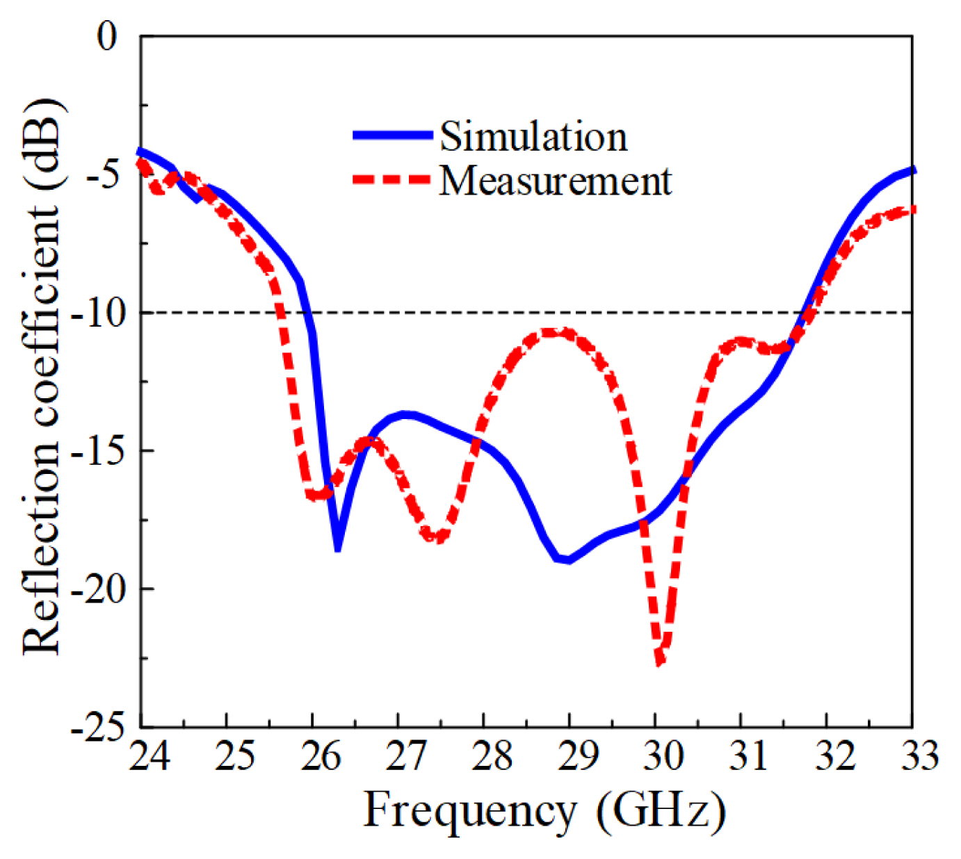
Measured and simulated reflection coefficients.

Measured and simulated axial ratio.
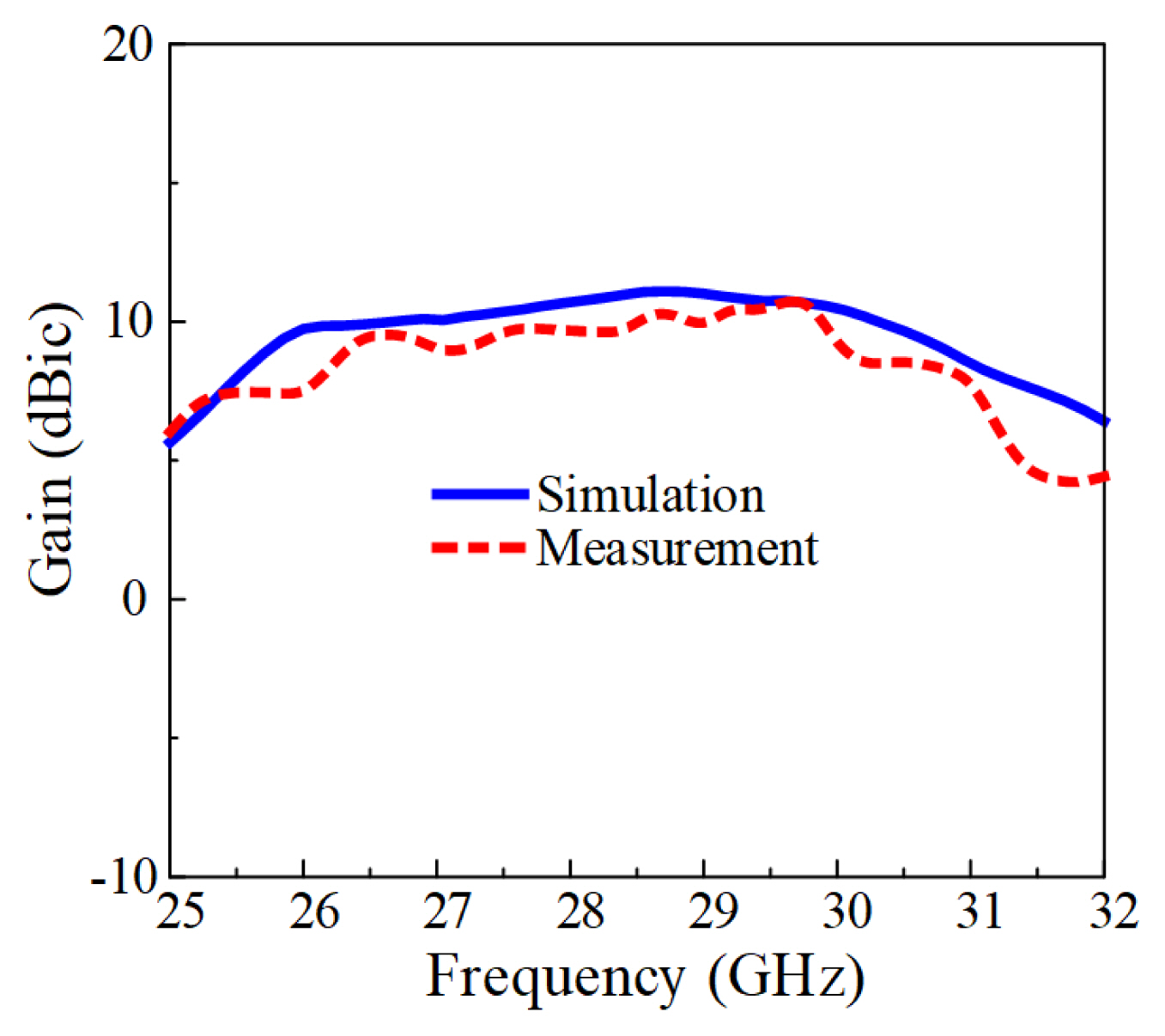
Measured and simulated gain.
Table 1 compares the LP-to-CP conversion performance of the proposed antenna with that of other end-fire antennas integrated with metasurfaces [21, 24, 39]. The criteria for selecting the papers presented in the table were based on a comparison of our antenna design’s size, AR bandwidth, and gain. The structure in [21] is relatively smaller than our proposed structure, but its impedance and AR bandwidths are narrower, and its gain is lower. The structure described in [24] has a profile similar to ours, but its impedance and AR bandwidths are narrower, and its gain is lower. The structure presented in [39] has a wider AR bandwidth, and the gain is similar to that of our proposed antenna. However, its impedance bandwidth is narrower, and its profile size is larger.
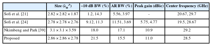
Performance comparison of the proposed antenna with other antenna designs
VI. Conclusion
This study presents a high-gain wideband CP antenna using non-uniform circular metasurface patches. The high-gain wideband CP antenna consists of a two-layer cascaded metasurface made up of 4 × 4 non-uniform circular patches with cross-slots of unequal lengths placed above the end-fire dipole array LP source antenna with an air gap. Cross-slot metasurface patches are used for the conversion of LP to CP waves. The proposed antenna with non-uniform metasurface patches shows improved gain and AR bandwidth characteristics relative to uniform metasurface patches. The measured results show that the antenna has an impedance bandwidth of 25.6–31.8 GHz (21.5%), an AR bandwidth of 26.1–30.5 GHz (15.5%), a peak gain of 11.0 dBic, and a high radiation efficiency greater than 80%. The proposed structure is a suitable candidate for 5G communication systems because of its distinct advantages, such as its high gain and wide AR bandwidth.
Acknowledgments
This work was supported in part by the National Research Foundation of Korea (NRF) grant funded by the Korea government (MSIT) (No. NRF-2022R1F1A1065324); in part by the National Research Foundation of Korea (NRF) grant funded by the Korea government (MSIT) (No. 2021R1A4A1030775); and in part by Institute of Information & communications Technology Planning & Evaluation (IITP) grant funded by the Korea government (MSIT) (No. 2022-0-00704-001, Development of 3D-NET Core Technology for High-Mobility Vehicular Service).
References
Biography

Cho Hilary Scott Nkimbeng received his B.Tech. degree in electrical and electronic engineering (telecommunication) from the University of Buea, Cameroon, in 2013 and his M.S. degree in electrical and computer engineering from Ajou University, Suwon, Republic of Korea, in 2018. He is currently studying for his Ph.D. in the Department of Electrical and Computer Engineering at Ajou University, Suwon, Republic of Korea. He was bestowed with the best paper award in 2022 for his presentation at the GSMM conference in Korea. His research interests include metasurface antennas, metamaterial-based antennas, circularly polarized antennas, miniaturized antennas, and bidirectional antennas.

Heesu Wang received his B.S. and M.S. degrees in electrical and computer engineering from Ajou University, Suwon, Republic of Korea, in 2018 and 2020, respectively. He is currently studying for his Ph.D. in the Department of Electrical and Computer Engineering at Ajou University, Suwon, Republic of Korea. His research interests include the design of patch antennas, printed antennas, small antennas, and metasurface antennas for various wireless communication applications.

Gangil Byun received his B.S. and M.S. degrees in electronic and electrical engineering from Hongik University, Seoul, Korea, in 2010 and 2012, respectively, and his Ph.D. degree in electronics and computer engineering from Hanyang University, Seoul, Korea, in 2015. After graduation, he returned to Hongik University to work as a research professor and performed active research for two years. He joined the faculty of the Ulsan National Institute of Science and Technology, Ulsan, South Korea, in February 2018, where he is currently an associate professor in the Department of Electrical Engineering. His principal research areas are the design and analysis of small antenna arrays for adaptive beamforming applications, such as direction-of-arrival estimation, interference mitigation, and radar. He has actively contributed to the improvement of overall beamforming performance by combining both antenna engineering and signal processing perspectives. His recent research interests include Huygens’ metasurface, optically invisible antennas, electromagnetic sensors, and waveguide slot array antennas to bring advances in future wireless communication systems.

Yong Bae Park received his B.S., M.S., and Ph.D. degrees in electrical engineering from the Korea Advanced Institute of Science and Technology, South Korea, in 1998, 2000, and 2003, respectively. From 2003 to 2006, he worked at the Korea Telecom Laboratory in Seoul, South Korea. He joined the School of Electrical and Computer Engineering, Ajou University, South Korea, in 2006, where he is currently a professor. His research interests include electromagnetic field analysis, high-frequency methods, metamaterial antennas, radomes, and stealth technology.

Ikmo Park received his B.S. degree in electrical engineering from the State University of New York at Stony Brook and his M.S. and Ph.D. degrees in electrical engineering from the University of Illinois at Urbana-Champaign. He joined the Department of Electrical and Computer Engineering at Ajou University, Suwon, Republic of Korea, in 1996. He has authored and co-authored over 400 technical journals and conference papers. He also holds over 50 domestic and international patents. He served as chair of the Department of Electrical and Computer Engineering at Ajou University, and he is a member of the Board of Directors at the Korea Institute of Electromagnetic Engineering and Science (KIEES). He also serves as the Editor-in-Chief of the Journal of KIEES, an Editorial Board member of the International Journal of Antennas and Propagation, an Editorial Board member of MDPI’s Electronics, and an Associate Editor of the IET’s Electronics Letters. He has also served as an editorial board member of the Journal of Electromagnetic Engineering and Science. He currently serves as chair, organizer, and member of program committees for various conferences, workshops, and short courses on electromagnetic-related topics. His present research interests include the design and analysis of microwave, millimeter-wave, terahertz wave, and nano-structured antennas with metamaterials and metasurfaces.