Measurement of Nonlinear RCS of Electronic Targets for Nonlinear Detection
Article information
Abstract
The conventional radar technology is based on linear detection—i.e., the same transmit and receive frequencies are used. However, with linear radars, difficulties arise when detecting electronic objects with relatively small radar cross section (RCS). To overcome these limitations, a nonlinear radar that can detect nonlinear responses (i.e., harmonic and intermodulation) scattered by electronic devices due to nonlinear interaction can be utilized. Nonlinear radars require a different analysis from linear radars for analyzing RCS. In this paper, we present an experimental analysis of the nonlinear RCS of various electronic devices. Unlike linear radars, RCS in nonlinear radars is determined by the amount of nonlinear responses backscattered to the radar. Therefore, we derive a radar equation accustomed to harmonic radars that consists of nonlinear RCS. We then obtain and analyze the nonlinear RCS of various targets from the measured harmonic responses of the targets based on the nonlinear radar equation.
I. Introduction
Radars have been widely used for remote detection of objects for military and commercial applications since its introduction in the 1930s. Conventional radars are based on “linear” detection— i.e., the radar uses the same transmit and receive frequencies and receives the transmitted pulse reflected from targets to determine their presence, distance, and speed. However, there is a limitation in linear radars in that it is difficult to detect an object with a relatively small scattering cross section, such as small electronic devices [1]. To overcome this limitation, “nonlinear” detection was proposed in the 1970s, which allows for the detection of the nonlinear responses of semiconductor junctions included in electronic devices [2]. For objects with nonlinear characteristics, an incident radar signal can excite nonlinear responses, which may refer to the harmonics or intermodulation of the incident signal produced by the nonlinear interaction in semiconductor devices [3–5]. If the reception is performed in the frequency band of the nonlinear response, it is possible to eliminate the linear responses and only receive nonlinear responses, thus being able to detect small electronic targets in the presence of linear targets with larger cross sections, which is difficult with linear radar techniques.
Hence, nonlinear radars require a different analysis and signal processing from conventional linear radars in order to detect electronic targets, since nonlinear interaction and scattering must be considered in the process. The radar cross section (RCS) of nonlinear targets is determined by the amount of nonlinear response backscattered to the radar, which is nonlinearly dependent on the incident power and electronics inside the target. Therefore, for a given nonlinear radar system, predicting and analyzing the “nonlinear RCS” of targets of interest would be important.
Recently, research on nonlinear radars based on harmonic and intermodulation detection using continuous wave (CW) and stepped frequency CW signals has been conducted [6–10]. The distinct capabilities of nonlinear radars allow them to be utilized over a wide range of applications. For military and security purposes, nonlinear radars can detect and identify concealed threat electronic devices as well as electronic devices beyond walls. In addition, nonlinear radars can be applied to search-and-rescue by detecting electronic devices possessed by personnel buried under ground due to natural disasters, such as avalanches and landslides. For medical purposes, vital signs can be sensed using harmonic tags [11].
In this paper, we present an experimental analysis of the nonlinear RCS of various electronic devices that we consider targets of interest. The nonlinear radar system considered here is a harmonic radar designed to detect the second harmonic responses of targets. We used an experimental apparatus that represents a harmonic radar system for detecting electronic targets at a short range (up to several meters) to measure the nonlinear RCS of various electronics devices.
This paper is organized as follows. We first define the “apparent RCS” and derive its mathematical representation from the conventional radar equation. We then define the nonlinear RCS and its relation to the apparent RCS, which allows the nonlinear radar equation to be derived. By applying the derived equations to the measured target responses, we calculate and analyze the nonlinear RCS of the targets.
II. Analysis of Nonlinear Radar Equation
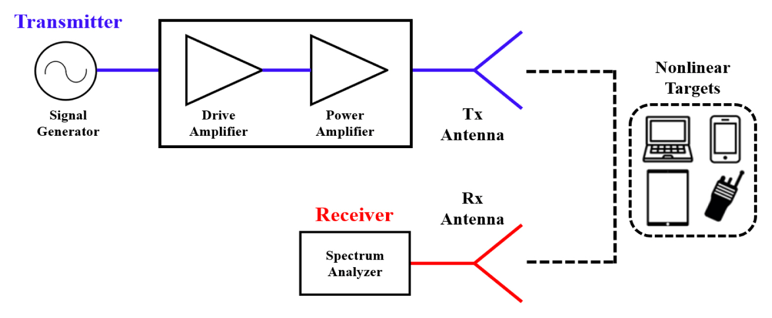
To analyze the nonlinear RCS of a target, it is essential to use a proper radar equation accustomed to nonlinear radars. In the case of nonlinear detection (harmonic-based), unlike the conventional linear radar equation, the radar cross section must be calculated based on the nonlinear response. Hence, it is necessary to express the radar equation, including the nth harmonic response of the target. Fig. 1 shows a simple schematic of nonlinear detection from the transmitter (Tx) to the receiver (Rx) for a nonlinear target at a distance of R. First, we start with the traditional linear radar equation format:

Schematic of a radar system targeting nonlinear objects.
where for harmonic detection, σ is the RCS as seen by the radar, Pt is the transmit power at the fundamental frequency, Gt is the gain of the transmitting antenna at the fundamental frequency, Gr is the gain of the receiving antenna at the harmonic frequency, and λ is the wavelength of the harmonic frequency. Eq. (1) can be re-expressed by separating the transmit, scattering, and receive parts of the process as
The first term in Eq. (2) describes the transmitted power density incident at the target, while the second term is the apparent RCS, σ′, as seen by the radar. Note that σ′=σ. The third term describes the power spread of the target response traveling back toward the Rx antenna. Finally, the last term contains the effective area of the Rx antenna. The total received power Pr is the product of the aforementioned terms.
Here, the radar equation is analyzed by treating the target as an effective antenna with an effective area [12–14]. By applying the process of nonlinear interaction at the target to Eq. (2), we can derive the nonlinear radar equation in a few steps as follows: the transmitted power density incident at the target can be expressed as the first term of Eq. (2). Assuming that the target has an effective area of Atg, the power received by the target, Pin, can be expressed as
The power excited from the nonlinear interaction in the target, Pout, can be expressed in the form of a power series (assuming memoryless):
where an is a scaling coefficient of the nth harmonic produced by the nonlinear characteristic of the target. The power at the nth harmonic, Poutn, can be extracted from the series in Eq. (4) and expressed as
Therefore, when the effective transmission gain of the target at the nth harmonic frequency is given as Gtgtn, the scattered power from the target can be expressed as
As Pscn travels back the distance of R toward the Rx antenna, the incident received power density, Srn, can be expressed as
By rearranging the terms in Eq. (7) using Eqs. (3)–(6) to be in line with Eq. (2), it can be rearranged as
The second term in Eq. (8) corresponds to the apparent RCS, σ′, which corresponds to the nth harmonic response scattered from the target. The parameters related to the nonlinear characteristics of the target are grouped together and defined as the nonlinear RCS, σn, which is then related to σ′ as
The nonlinear RCS, σn, describes the physical and nonlinear characteristics of the target and can be expressed as
As with the linear RCS, σ′ has the unit of m2. Unlike the linear RCS, its value depends on the transmit power, gain, and distance that determine the incident power level at the target. On the contrary, the nonlinear RCS, σn, describes the physical and nonlinear characteristics of the target at the nth harmonic. Therefore, the unit of σn depends on the harmonic order and is expressed as m2/(Wn−1/m2n−2), as indicated by Eq. (9). The total received power, Prn, can then be obtained via the product of Srn and the effective area of the Rx antenna as
By substituting Eq. (9) into Eq. (10)Prn can be expressed using σn as
which is referred to as the nonlinear radar equation [7].
Therefore, the nonlinear RCS of targets from the measurement can be directly obtained by using Eq. (12). Alternatively, we can first obtain σ′ using Eq. (11) from the received power and then determine the nonlinear RCS using Eq. (9). In the case of n = 2 (second harmonic), σ2 can be obtained as
which has a unit of m4/W.
III. Nonlinear Radar Measurement and Analysis
A measurement environment was established in an anechoic chamber, as illustrated in Figs. 2 and 3. In the setup, an Agilent E4436B signal generator was used to generate the transmit signal, and a Cree CMPA2735075F1 amplifier was used for amplification. A transmit power of 18.2 W (42.6 dBm) was used. The Tx antenna has a gain of 16.7 dBi at a fundamental frequency of 3.1 GHz, and the Rx antenna has a gain of 16 dBi at the second harmonic frequency of 6.2 GHz. The received signal was measured using an Agilent E4407B spectrum analyzer. Note that in general, the amplitude of the harmonic response is significantly lower than that of the fundamental response. Therefore, for successful harmonic detection, sufficient transmit power, gain of Tx/Rx antenna, and suppression of background/self-generated harmonics are required.
Nonlinear radar measurement environment setup with various nonlinear targets.
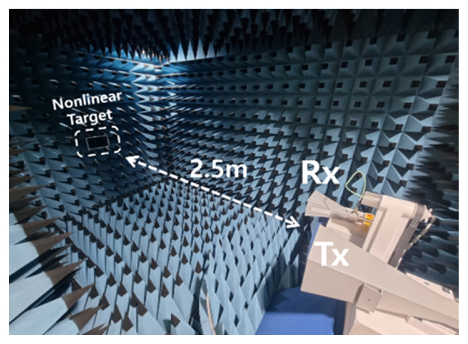
Measurement environment in a chamber where the target is at a distance of 2.5 m from the antennas.
In the absence of targets, a background signal level of −64.21 dBm at 6.2 GHz was measured. As shown in Fig. 3, each target measurement was carried out with the target located 2.5 m from the Tx/Rx antennas. Each target was oriented in such a manner that the incident electromagnetic waves are normally incident on the largest area of the target. Table 1 shows the types and physical cross sections of the nonlinear targets used in the measurement as well as the received power level of the harmonic response from each target. The results show that the received signal levels are well above the background level, indicating successful detection of nonlinear responses from targets.
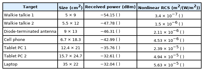
Various nonlinear targets and the received power
Based on the measured received power, Eqs. (11)–(13) were applied to obtain the nonlinear RCS, which is also indicated in Table 1. In addition, the received power and nonlinear RCS of the measured targets are plotted as a function of their size in Fig. 4. It shows that the measured nonlinear RCS values are on the order of 10−5 m4/W, which falls within the general range of nonlinear RCS (second harmonic) of 10−8–10−5 m4/W as suggested in the literature [2]. Furthermore, it can be seen that the value of σ2 and received power is roughly proportional to the physical size of the target. Such a relation can be attributed to two possible reasons. As shown in Eq. (10), nonlinear RCS σn consists of Gtgtn, the effective gain at the nth harmonic frequency, and Atg, the effective area of the target. The increase in the physical size of the target generally follows the size of the electronic boards within the target, which in turn increases Gtgtn and Atg of the target. Also, the increase in the electronic board size should also be roughly proportional to the number of semiconductor devices attached, which may result in a high level of excited harmonic response (i.e., an increase in the values of an).

Received power and nonlinear RCS graph according to the target size.
IV. Conclusion
In this paper, we carried out measurements of the second harmonic-based nonlinear RCS of various electronic devices by using an experimental apparatus that represents a harmonic radar system. For analysis, the nonlinear radar equation was derived. In this process, apparent and nonlinear RCS were defined, which were then used to determine the measured nonlinear RCS of targets. The measured nonlinear RCS values were shown to fall within the expected range. Such an analysis of nonlinear RCS can be useful in predicting the performance of a nonlinear radar when designing and modeling the system.
Acknowledgments
This research was supported by the Challengeable Future Technology Research and Development Program (No. 912902601) of Agency for Defense Development in 2020.
References
Biography

Soo Young Oh received his B.S. degree in electronic engineering from Soongsil University, Seoul, South Korea, in 2021, and is currently pursuing his combined M.S./Ph. D. degree in electronic engineering at Soongsil University. His research interests include nonlinear radars and antennas for nonlinear detection.

Kyu Ho Cha received his B.S. degree in electronic engineering from Soongsil University, Seoul, South Korea, in 2021. He is currently pursuing his M.S. degree at Soongsil University. His research interests include antennas, nonlinear detection, and microwave and millimeter-wave devices.

Hayoung Hong received her B.S. and M.S. degrees in electronic engineering from Soongsil University, Seoul, South Korea, in 2020 and 2022, respectively. She is currently pursuing her Ph.D. degree at Soongsil University. Her research interests include wireless power transfer, antennas, radars, microwaves, and millimeter-wave devices.

Hongsoo Park received his B.S. (with honors) and M.S. degrees in electronic engineering from Soongsil University, Seoul, South Korea, in 2019 and 2021, respectively. He is currently pursuing his Ph.D. degree at Soongsil University. His research interests include wireless power transfer, antennas, microwave and millimeter-wave devices, electromagnetic time-reversal, and electromagnetics in complex environments.

Sun K. Hong received his B.S. degree in electrical engineering from the University of Maryland, College Park, MD, USA, in 2005, and his M.S. and Ph.D. degrees in electrical engineering from Virginia Tech, Blacksburg, VA, USA, in 2008 and 2012, respectively. From 2005 to 2015, he was a research engineer at the US Naval Research Laboratory. From 2015 to 2017, he was an assistant professor at the Department of Electrical and Computer Engineering, Rose-Hulman Institute of Technology, Terre Haute, IN, USA. In 2017, he joined the School of Electronic Engineering at Soongsil University in Seoul, where he is an associate professor. His current research interests include wireless power transfer, electromagnetic waves in complex propagation environments, detection of nonlinear devices, radars, and high-power electromagnetics.
 )
) )
) )
) )
) )
) )
) )
) )
) )
) )
) )
) )
) )
) )
)