Design of Broadband Compact Canonical Triple-Sleeve Antenna Operating in UHF Band
Article information
Abstract
In this paper, a novel compact broadband antenna at UHF frequencies is presented with canonical shapes. Hemispherical, conical and cylindrical shapes have all been considered for antenna configuration. The designed antenna provides an instantaneous frequency range from 370 to 5,000 MHz with omnidirectional characteristics. The antenna was simulated in CST Microwave Studio, fabricated and evaluated; the results are presented. The simulated and measurement results are in good agreement. The antenna has voltage standing wave ratio (VSWR) ≤ 1.9:1 in 400–570 MHz, 2,530–3,740 MHz and 4,180–4,620 MHz; it has VSWR ≤ 3:1 over the operating frequency range 370–5,000 MHz and the measured gain varies from −0.6 to 4.5 dBi over the frequency band. The concept of canonical-shaped antenna elements and the incorporation of triple sleeves resulted in a reduction of the length of the antenna by 62% compared to the length of a half-wave dipole antenna designed at the lowest frequency. The antenna can be used for trans-receiving applications in wireless communication.
I. Introduction
Compact broadband omnidirectional antennas are in high demand for a wide range of applications in the wireless communication and defense system industries. Discone and biconical antennas are conventional broadband omnidirectional antennas designed to operate over multi-octave frequency ranges [1, 2]. However, the conical sections of these antennas have dimensions of the order of quarter wavelength at the lowest frequency. Thus, the dimensions of these antennas become large when implemented in VHF/UHF bands. Researchers in the field have been active in studying design techniques for realizing omnidirectional antennas with broad bandwidth and compact size with several notable findings reported in the literature. Sleeve monopole antennas using open sleeve configurations have been reported for broad bandwidths [3, 4]. Such antennas require very large ground planes. Dual sleeve antennas with reduced size ground planes have also been reported in [5]. A sleeve antenna mounted on a cylindrical ground plane having 4:1 bandwidth ratio is presented by Zhou et al. [6]. Yang et al. [7] designed a novel wideband sleeve dipole array operating between the frequency range 707–3,300 MHz. A sleeve monopole antenna with top-loading and shorting pins have been implemented by Ravipati and Reddy [8], achieving a bandwidth ratio of 3.7:1 and a bandwidth ratio of 4.28:1 by Ghafari and Aloi [9]. Bandwidth enhancement using matching networks are reported by several studies [10–13]. Matching networks enhance bandwidth at the expense of antenna efficiency. Dual sleeve antenna with load is demonstrated in [14] operating between the frequency range 57–103 MHz.
Several other dual sleeve antenna designs have also been reported. These antenna designs operated in different frequency ranges as follows: 400–900 MHz by Wang et al. [15], 500–2,100 MHz by Thomas et al. [5] and 120–520 MHz by Zhang et al.[16]. Sleeve dipole antenna with 2.9:1 bandwidth is reported in [17]. Sleeve dipole antenna with three sleeves was reported in [18]. An Antenna with conical shaped sleeve operating between the frequency range 446–732 MHz was demonstrated by Zhang et al. [19]. A low profile antenna with conical shaped radiator, cylindrical sleeve, top-loading and shorting pins is designed to operate in the frequency range 750–2,660 MHz [20]. A compact broadband omnidirectional antenna using canonical structures and single sleeve configuration was designed by Sai-Ram et al. [21] to operate in the frequency range 500–3,000 MHz. Half disc dipole antenna has been noted to exhibit broadband omnidirectional characteristics [22]. Finally, Gao and Lu [23] designed a printed wideband dipole antenna operating in the range of 650–1,150 MHz.
In this paper, a canonical triple sleeve antenna having compact broadband omnidirectional characteristics in 370–5,000 MHz is presented overcoming several limitations of earlier designs mentioned above. Novel concepts using canonical shaped radiating elements with triple sleeves are employed for achieving much wider bandwidth with compact form factor, compared to other sleeve antennas reported in the literature.
II. Design and Implementation of Canonical Triple Sleeve Antenna
A conventional cylindrical dipole antenna is a narrowband resonant antenna. The bandwidth of this dipole antenna can be increased by increasing the diameter of the dipole. More bandwidth is achieved by increasing the resistance and reducing the reactance, compared to a thin dipole antenna.
The concept of sleeves can also be used to increase the bandwidth of this dipole antenna. A sleeve modifies the current distribution of the antenna and enhances its bandwidth. The design of the canonical triple sleeve antenna begins with a basic canonical antenna structure, resulting from a combination of hemispherical dipoles with conical and cylindrical extensions, fed at the center, as shown in Fig. 1.

Simulation models of (a) canonical antenna, (b) canonical single sleeve antenna, (c) canonical dual sleeve antenna, and (d) canonical triple sleeve antenna.
The antenna is designed for the center frequency of fo = 2,685 MHz, and the corresponding wavelength is λo = 111.73 mm. Antenna design is carried out using genetic algorithm optimization in CST Microwave Studio for the operating frequency band of 370–5,000 MHz.
The design parameters of the antenna are varied around their nominal design values as follows:
Design of canonical antenna: The canonical antenna is designed as a combination of the hemisphere, cone and cylinder, respectively, starting from the feed gap.
Design of hemisphere section: The diameter of the hemisphere is obtained as 0.13λo.
The diameter of the conical section at its one end is selected to match the hemispherical section, which is 0.13 λo and the diameter of the other side of the cone is obtained as 0.77λo.
The conical section is further extended with a cylindrical section of diameter 1.01λo and a height of 0.17λo.
This antenna structure is further augmented by a single sleeve placed symmetrically with respect to the feed point resulting in canonical single sleeve antenna as shown in Fig. 1(b). The details of this augmentation are as follows:
Design of canonical single sleeve antenna: A canonical antenna is designed with a central sleeve. The diameter and length of the first (central) sleeve are obtained as 1.05λo and 0.22λo, respectively.
Design of canonical dual sleeve antenna: canonical antenna is designed with two sleeves symmetrically placed around its feed point. The diameter and length of the sleeves are obtained as 0.81λo and 0.12λo, respectively. Canonical antenna with two sleeves result in the canonical dual sleeve antenna as shown in Fig. 1(c).
Design of canonical triple sleeve antenna: canonical antenna is designed with a first (central) sleeve and two sleeves symmetrical around it. Canonical triple sleeve has evolved from the canonical single sleeve antenna by adding two more sleeves and placing them equidistant from the first sleeve and is shown in Fig. 1(d).
The simulation models of these antennas are shown in Fig. 1.
The diameter of the hemisphere is obtained as 0.13λo. The diameter of the conical section at its one end is selected to match to the hemispherical section, which is 0.13λo, and the diameter of the other side of the cone is obtained as 0.77λo. The diameter and length of the first (central) sleeve are obtained as 1.05λo and 0.22λo, respectively. The diameter and length of the second and third sleeves are obtained as 0.81λo and 0.12λo, respectively. The parameters of the canonical triple sleeve antenna are given in Table 1.

Canonical triple sleeve antenna parameters
The variations in resistance and reactance of the input impedance of the proposed antenna configurations are shown in Fig. 2(a) and 2(b).
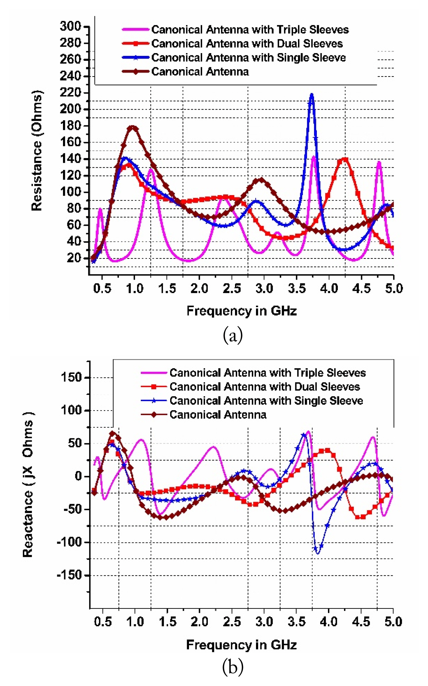
Comparison of (a) resistance and (b) reactance.
As inferred from Fig. 2(a) that the resistance of input impedance has lower values for canonical antenna and canonical single sleeve antennas compared to canonical dual sleeve and canonical triple sleeve antennas. There is a substantial increase in resistance of input impedance for canonical dual sleeve and canonical triple sleeve antennas. The overall variation in resistance of input impedance is comparatively lower for the canonical triple sleeve antenna than canonical dual sleeve antenna over the frequency band 370–5,000 MHz. Variation in the reactance of input impedance is observed to be more for canonical antenna and canonical single sleeve antenna, and less for canonical dual sleeve and canonical triple sleeve antennas. The comparison of simulated voltage standing wave ratio (VSWR) of these antenna configurations is shown in Fig. 3.

Simulated VSWR of antennas.
It can be observed from Figs. 2 and 3 that the canonical triple sleeve antenna has the best impedance matching and hence VSWR performance in the broadband scenario from 370–5,000 MHz.
1. Parametric Study
The structure of the proposed antenna the, canonical triple sleeve antenna is shown in Fig. 4. The performance of the canonical triple sleeve antenna was simulated with respect to the dimensions and placement of the sleeve. Initially, parametric analysis was performed for the first/central sleeve. The diameter of the first sleeve, j, varied from 50 to 150 mm in seven steps; the results are presented in Fig. 5(a).
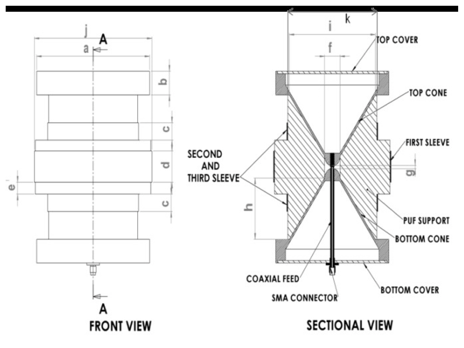
Structure of canonical triple sleeve antenna.
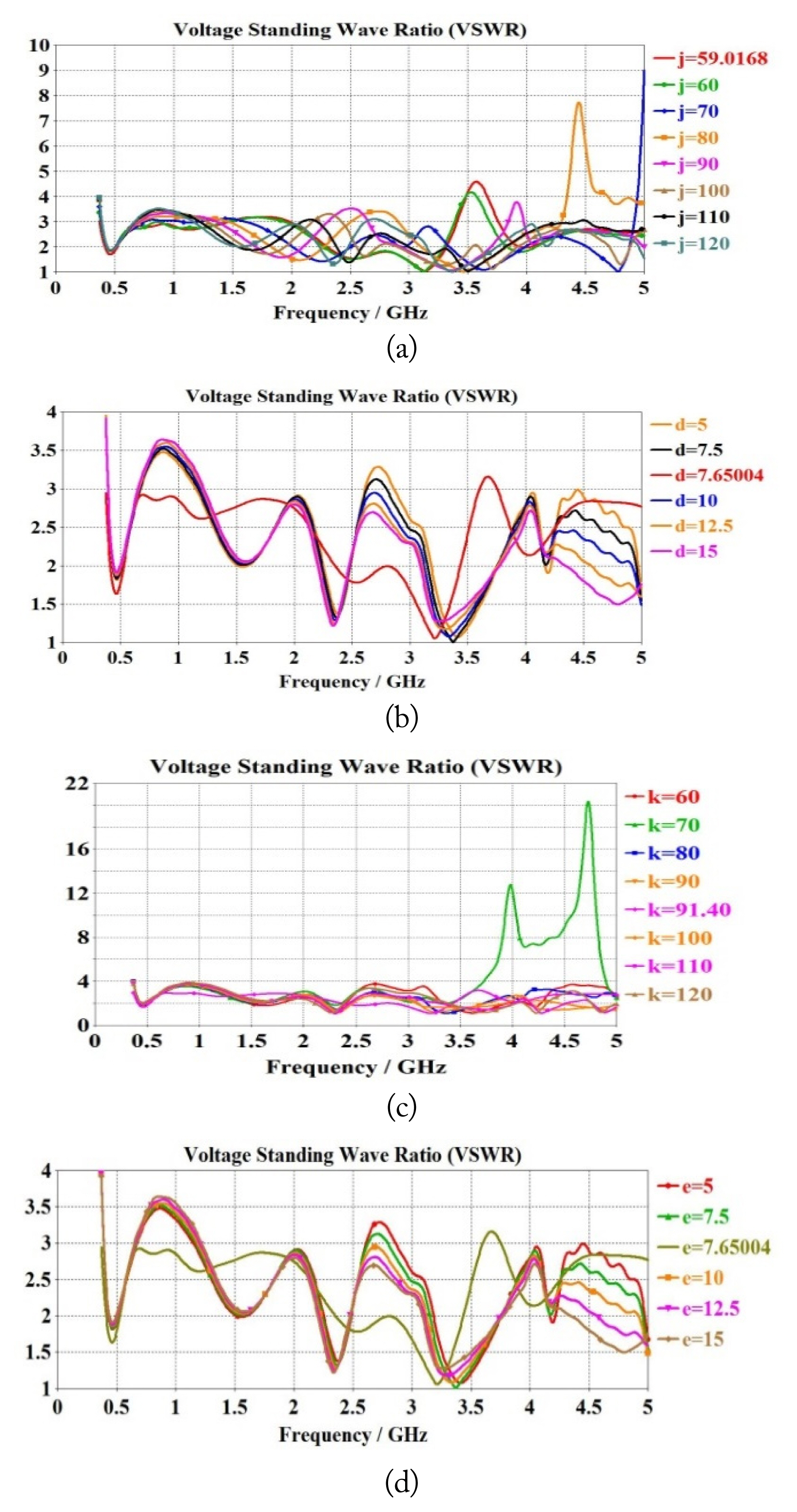
Results of parametric study: (a) diameter of first sleeve, j, (b) length of first sleeve, d, (c) diameter of second sleeve, k, and (d) spacing between first and second sleeve, e.
The plot also represents the VSWR for the best value of j = 59.01. The parametric study with respect to the first sleeve length, d is presented in Fig. 5(b). The results of the parametric study with respect to the diameter of the second and third sleeves, k, is shown in Fig. 5(c). The value of k is varied from 60–120 mm, and the best value is found to be 91.4 mm. The results of the parametric study for length of the second and third sleeves, c, are shown in Fig. 5(d). The parametric study with respect to the position of the second and third sleeves, e, is shown in Fig. 5(e).
The values of the best parameters for the canonical triple sleeve antenna are shown in Table 1.
The canonical triple sleeve antenna has a height of 153.68 mm and a diameter of 118.02 mm. The size of a half-wave dipole antenna at 370 MHz is 405.4 mm. Hence, the design of this antenna has resulted in a 62% size reduction compared to a half-wave dipole antenna at its lowest operating frequency.
The surface current distribution of the antennas was also studied by simulation. The current distributions at 370, 2,000, and 5,000 MHz are shown in Fig. 6.
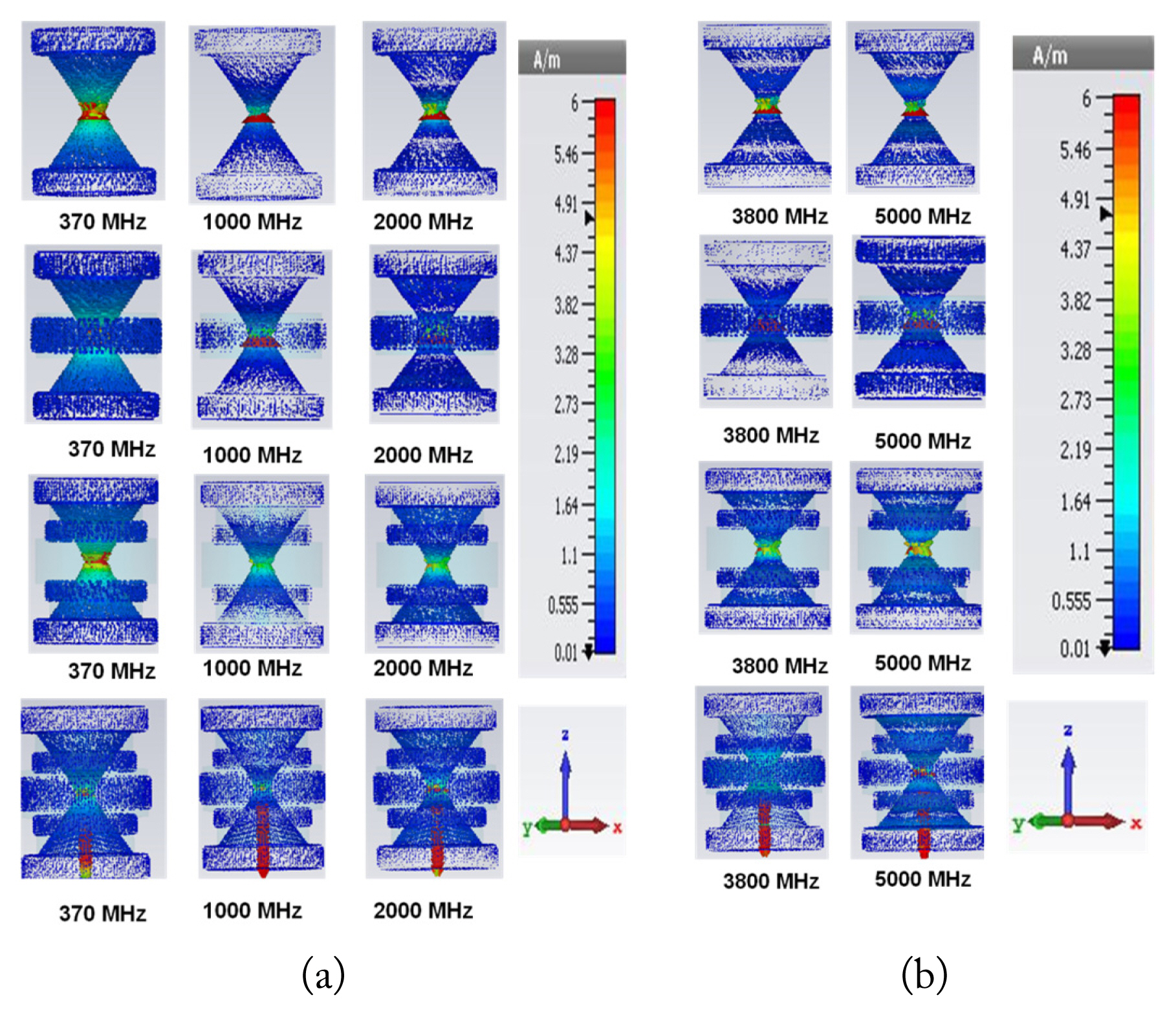
Current distributions for canonical antenna, canonical single sleeve antenna, canonical dual sleeve antenna and canonical triple sleeve antenna (a) at 370 MHz, 1,000 MHz and 2,000 MHz and (b) at 3,800 MHz and 5,000 MHz.
It was observed that the current is at its maximum at the feed point with all antenna configurations. At a low frequency of operation, significant current distribution exists over the whole antenna structure for the canonical antenna and canonical single sleeve antenna. Significant current distribution exists on the sleeves and accounts for the broadband performance of these antennas. As the frequency increases, the current intensity reduces towards the ends with all antennas. However, this trend is more pronounced as the number of sleeves increases. The length of all antennas is 2.56 wavelengths at 5,000 MHz. A conventional dipole of this length would have multiple lobes.
The simulation model and the photograph of the realized canonical triple sleeve antenna are shown in Fig. 7. The metallic portions of this antenna were fabricated using aluminum alloy. Poly-urethane foam (PUF) supports were used for the assembly of the antenna.
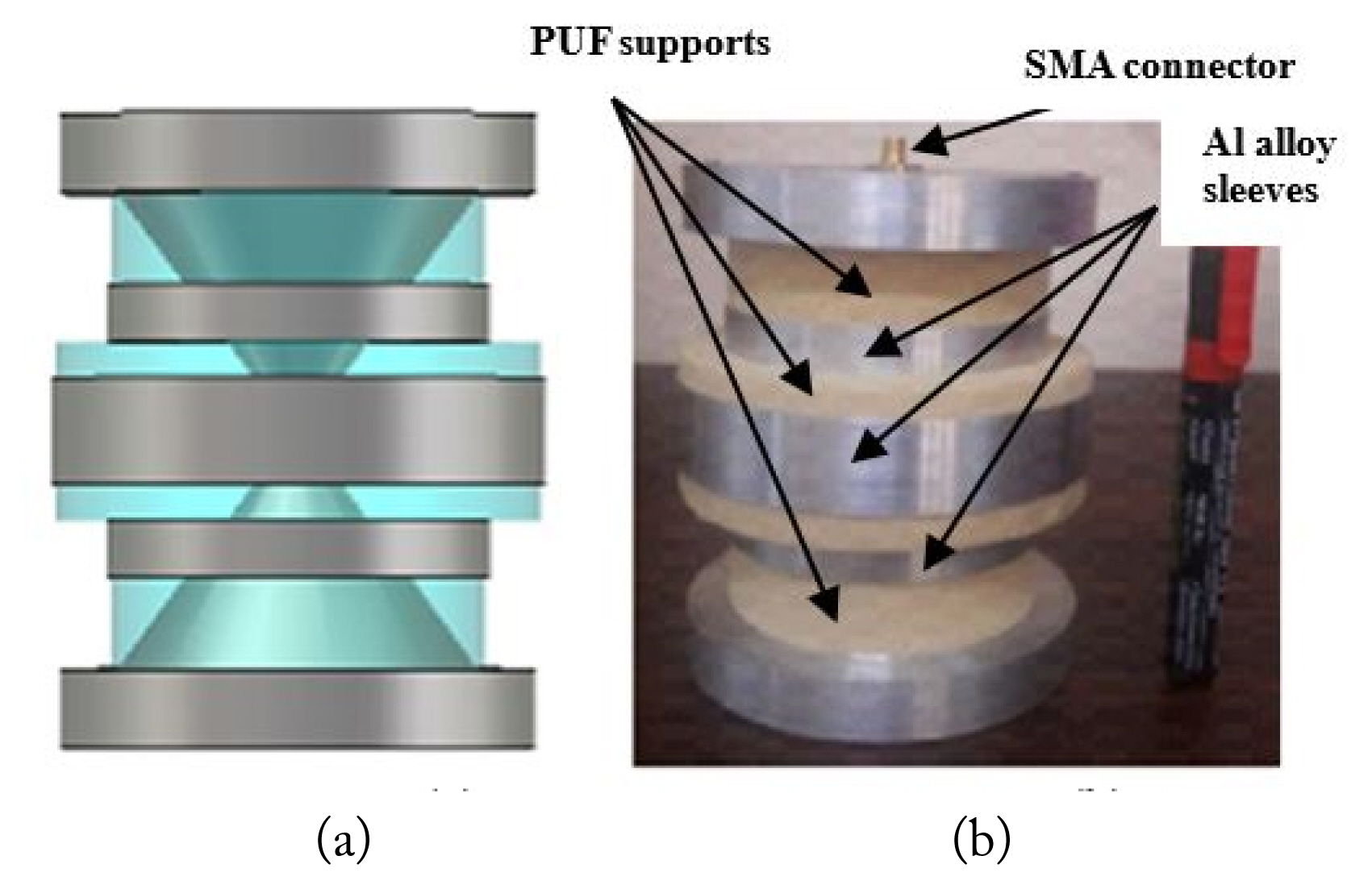
(a) Simulation model and (b) realized antenna.
The antenna was fed using a semi-rigid coaxial cable of 0.141-inch diameter. The coaxial cable was assembled with an SMA connector at one end as shown in Fig. 4.
III. Measured Results and Discussion
The VSWR measurement of canonical triple sleeve antenna is performed using a Vector Network Analyzer. The comparison of simulated and measured VSWR is given in Fig. 8.

Simulated and measured VSWR of canonical triple sleeve antenna.
The antenna has VSWR ≤ 1.9:1 in the frequency bands 415–530 MHz, 1,630–2,500 MHz and 4,560–5,000 MHz and VSWR ≤ 3:1 over the operating frequency range 370–5,000 MHz.
The measured and simulated E-plane and H-plane patterns of canonical triple sleeve antenna are shown in Fig. 9. It can be seen from Fig. 9 that the canonical triple sleeve antenna exhibits good omnidirectional characteristics. The measured omni-deviation is less than ±3 dB. The measured E-plane 3 dB beamwidth of the antenna varies from 15° to 120° over the frequency range 370–5,000 MHz. The measured radiation patterns are in good agreement with the simulated patterns.
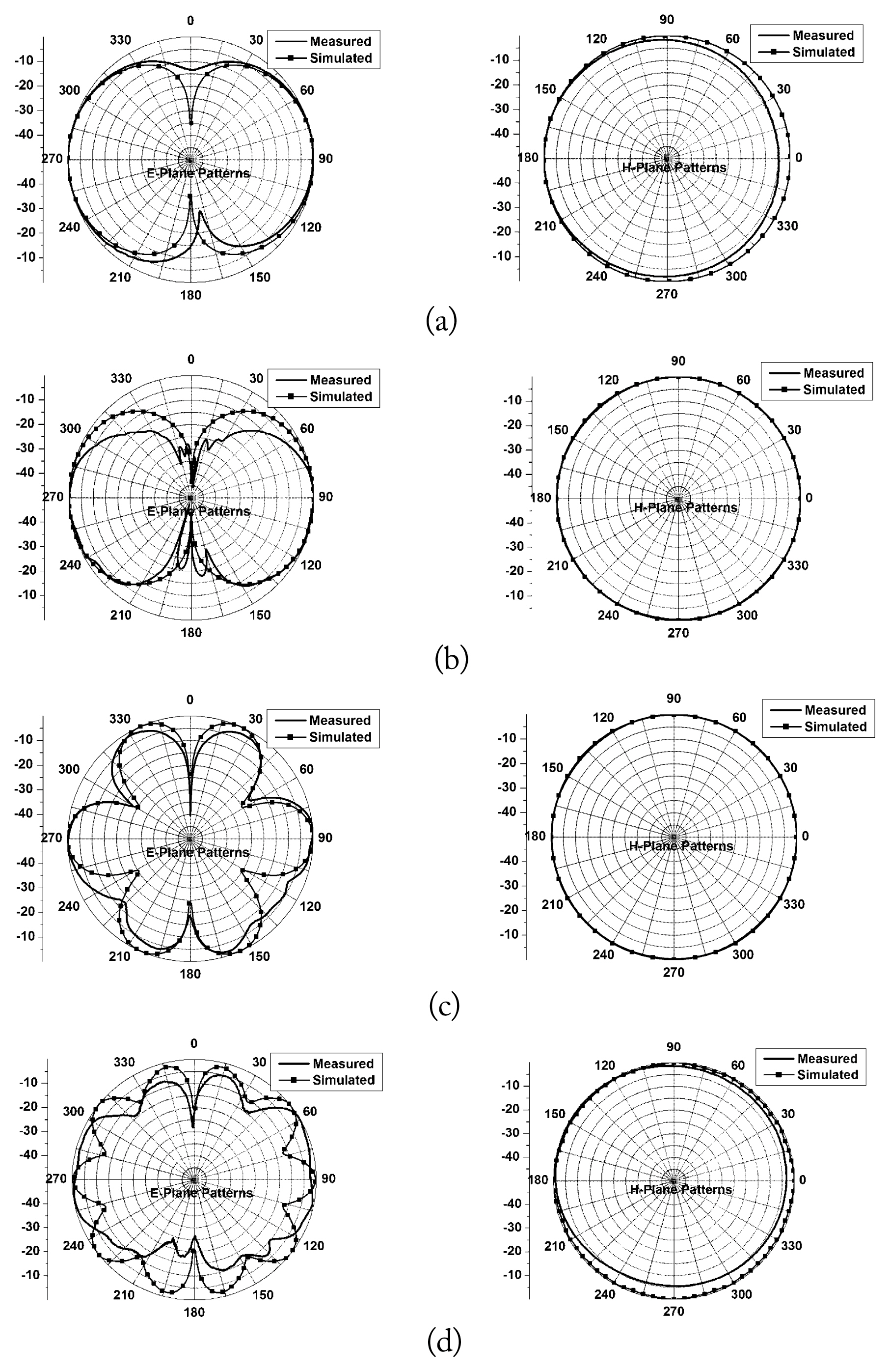
Simulated and measured radiation patterns of canonical triple sleeve antenna at 370 MHz (a), 2,000 MHz (b), 3,500 MHz (c), and 5,000 MHz (d).
The comparison of simulated and measured gain of the antenna is shown in Fig. 10. The measured gain of the antenna varies from −0.6 dBi to 4.5 dBi.
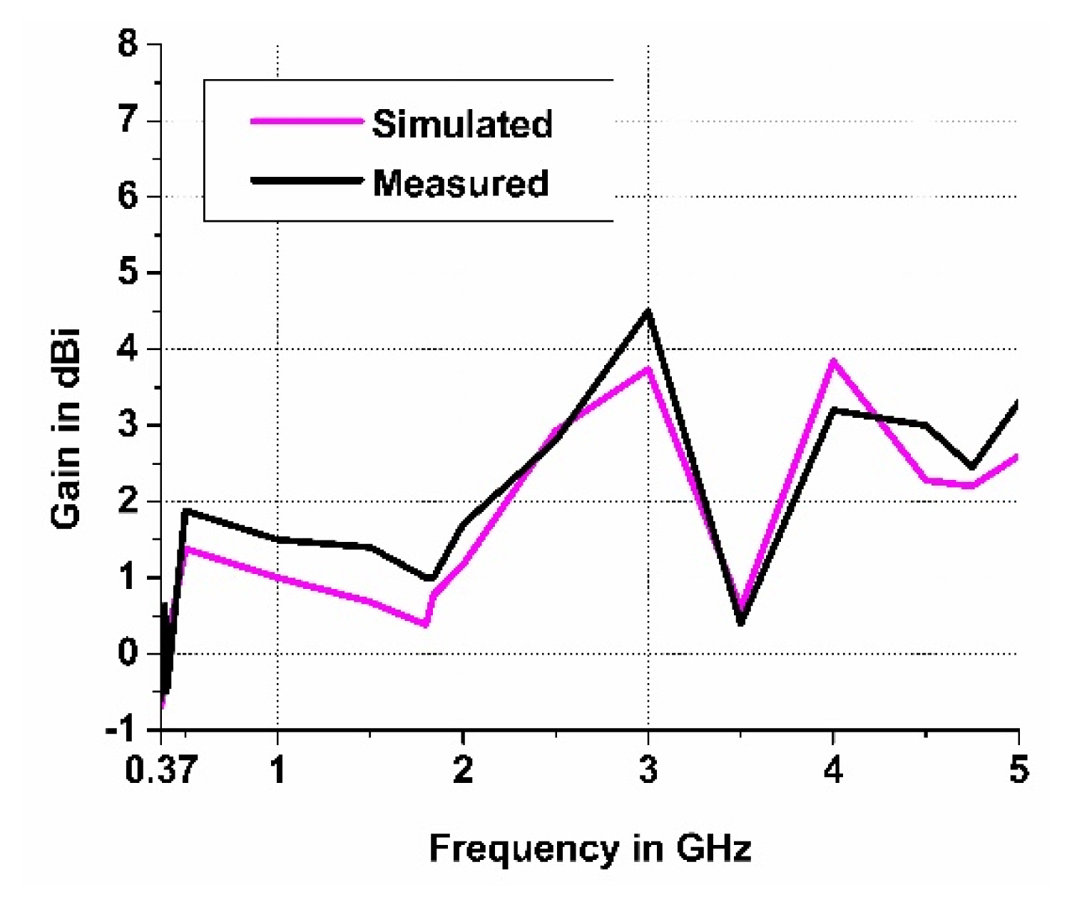
Simulated and measured gain plot of canonical triple sleeve antenna.
A comparison of the performance of the canonical triple sleeve antenna with existing published literature is shown in Table 2. It can be inferred that the proposed antenna, canonical triple sleeve antenna, has wideband characteristics and overcomes the limitations of the earlier designs with small form factor.

Comparison of canonical triple sleeve antenna with published literature
IV. Conclusion
A compact broadband canonical triple sleeve antenna was designed and realized, to operate in the frequency range 370–5,000 MHz. The antenna has a bandwidth ratio of 13.51:1, catering to the needs of several wireless communication systems, spectrum monitoring, law enforcement and defense systems. The antenna configuration consists of a basic antenna comprised of canonical shaped hemispherical dipoles with conical, cylindrical extensions and three coaxial sleeves. The novel concepts of canonical antenna structure and triple sleeves has resulted in broadband antenna with compact form factor.
Acknowledgments
The authors would like to thank Dr. A. K. Singh, OS & Director, DLRL, for his constant encouragement and support in carrying out the research work.
References
Biography

Chandana SaiRam graduated in ECE from Osmania University, Hyderabad, India in 1993. He has designed and developed a wide variety of broadband antennas for electronic warfare applications at DLRL, India. He has published over 50 papers in international Conferences and Journals. His areas of interest are in broadband HF/VHF/UHF antennas, wireless communication systems and computational electromagnetics. He is a member of IEEE, member of AOC and a fellow of IETE, New Delhi, India. He is also pursuing a part-time Ph.D. from the National Institute of Technology, Warangal, India.

Vakula Damera received her bachelor’s degree in Electronics and Communication Engineering (1992) from Nagarjuna University, AP, India, and a Master’s degree (1994) in Technology from Birla Institute of Technology, Mesra, India, with Microwave specialization. She obtained Ph.D. on fault diagnostics of antenna arrays from the National Institute of Technology, Warangal, in 2010. She is working as associate professor at the National Institute of Technology, Warangal, India. She has published 31 papers in international conferences and journals. Her areas of interest include phase array antennas, ultra wideband antennas, multiband antennas, fault diagnostics, and Neural networks. She is member of IETE, New Delhi, and ISTE, India.

Mada Chakravarthy obtained a B.Tech (ECE) from JNTU College of Engineering, Kakinada, India in 1986 and an M.E (MRE) from the University College of Engineering, Osmania University, Hyderabad, in 1996 and Ph.D from the University College of Engineering, Andhra University, Visakhapatnam in 2012. He has designed and developed multioctave band microwave electronic warfare antennas, radomes and antenna subsystems for defense applications at DLRL, India. He is a member of AOC and IETE, New Delhi, India.