Heuristic Incremental Theory of Diffraction for a Wedge with Impedance Surfaces
Article information

Abstract
This paper proposes a novel incremental theory of diffraction (ITD) formulation to calculate the fringe field from a wedge characterized by impedance surfaces and arbitrary exterior angles. The ITD formula was originally based on the Fourier transform pair relationship between the solution for the canonical wedge problem and incremental field contribution. However, this procedure can be utilized to report the ITD formula only for planar and half-planar impedance surfaces. Therefore, this paper develops a heuristic ITD formula by conceptually deriving the incremental diffracted field contribution from the uniform theory of diffraction coefficient and inferring the physical optics edge-diffracted field contribution from the terms related to the incidence shadow and reflection shadow boundaries. The proposed formula is applied to simple triangular impedance cylinder and disk models with impedance surfaces, and the results are compared with those of the method-of-moment and VIRAF’s ITD solver to show that is performs similar to the former and better than the latter.
I. Introduction
High-frequency asymptotic methods have been widely utilized to estimate electromagnetic scattering from an electrically large target [1–3]. For instance, these methods have been used in the design and analysis of antennas, estimation of the radar cross sections (RCS) of radar targets [1], prediction of propagation channels in complex environments [2], and analysis of antenna installation and inter-antenna coupling [3]. With the recent introduction of a variety of communication applications, interest in high-frequency methods, such as geometrical optics (GO), geometrical theory of diffraction (GTD), uniform theory of diffraction (UTD), physical optics (PO), and physical theory of diffraction (PTD) [4], has only increased.
GO, which is based on ray optics, accounts for direct and reflected ray fields. The reflected ray field in GO comprises non-zero fields only in the specular direction and is characterized by discontinuity of the field at the shadow boundaries. In contrast, the diffracted ray field, propelled by the UTD, can provide a nonzero field even in shadow regions. On the other hand, PO yields surface reflection from a finite surface using GO surface currents and the fringe currents given by the PTD provide edge correction for the PO. Therefore, the total scattered field can be calculated as the sum of the PO scattered field and the fringe field, also known as the PO edge-scattered field.
Since both the GTD and PTD are based on the postulate that high-frequency scattering is either a local phenomenon or a superposition of a local phenomenon, it is not without limitations. For instance, caustic singularities are applicable when the observation points are located at a caustic site or outside the cones of diffraction. To address this problem, researchers have devised incremental theories for edge bodies. In this context, while incremental length diffraction coefficients (ILDC) [5], equivalent edge currents [6], and equivalent edge waves [7] deduce incremental field contributions from the currents of local canonical wedge problems, the equivalent current method and the incremental theory of diffraction (ITD) [8] use incremental field contributions deduced from the fields of local canonical wedge problems.
These high-frequency methods have been developed to ensure perfectly conducting objects and wedges. Furthermore, in response to the growing interest in designing targets with low radar cross-sections and estimating wave propagation in complex environments using various non-perfectly conducting materials, reflection and diffraction solutions for non-perfectly conducting surfaces and wedges have been proposed in the literature [9–15]. Notably, since Maliuzhinets [9] first developed a diffraction solution for wedges with impedance boundary conditions (IBCs), most diffraction coefficients for impedance surface wedges have been based on Maliuzhinets’ solution. However, since Maliuzhinets’ solution is a normal incidence solution that is complex to use, heuristic diffraction coefficients have primarily been utilized.
For ray-based methods, such as ray launching GO, the total scattered field can be obtained by summing the GO field and the diffracted field, calculated by multiplying the diffraction coefficient and the incident field. Meanwhile, PO-based methods, such as the shooting and bouncing rays method, require calculating the fringe field, which can be obtained by subtracting the PO edge-diffracted field from the diffracted field. This indicates that calculating the fringe field from an arbitrary wedge with impedance surface necessitates additional formulas for the PO edge-diffracted field as well as for the diffraction coefficient of the diffracted field. However, there is limited literature available on estimating the fringe field from an impedance surface wedge with an arbitrary external angle.
Syed and Volakis [10, 11] derived an approximate dyadic diffraction coefficient for an impedance wedge by approximating the near-normal incidence or small wedge angle, presenting the ILDC for a curved wedge, and then developing the PO diffraction coefficient through the lower-limited integration of the PO surface current. The results of this formula agreed well with those of the method-of-moment (MoM), although the formula itself, especially the diffraction coefficient, was quite cumbersome to use and had to be expressed differently depending on the observation point.
In response to these challenges, explicit ITD formulations have been developed to successfully derive the fringe field of perfect equivalent conductor (PEC) local wedges, PEC local thin circular cylinders, and double local edges [8, 16, 17]. Moreover, a closed-form ITD formula for a wedge with specific exterior angles, such as a plane (n = 1) and a half-plane (n = 0.5) [12, 13], has also been introduced. However, to the best of the authors’ knowledge, the literature has yet to report any ITD formula applicable for a wedge comprising impedance surfaces with arbitrary external angles. However, without specific explanation or formulation, the ITD solver for an arbitrary wedge with impedance surfaces is implemented in IDS’s Virtual Aircraft Framework (VIRAF)—an electromagnetic modeling and simulation tool—to capture the fringe field generated from a wedge with an impedance surface.
Based on explicit ITD formulations for PEC wedges, this paper proposes heuristic ITD formulations to estimate the fringe field from local edges with impedance planar surfaces.
The main contributions of this study are as follows:
· It proposes heuristic ITD formulations for arbitrary wedges with impedance surfaces.
· It establishes the dyadic diffraction coefficient and the PO diffraction coefficient based on the original explicit ITD formulation and UTD diffraction coefficients.
· The dyadic and PO diffraction coefficients are simple in form and are well matched with each other.
· The proposed heuristic ITD formula is validated by comparing its fringe field with those of the VIRAF ITD solver and MoM/IBC PO.
The remainder of this paper is organized as follows: Section II describes the formulations of previously proposed explicit and proposed heuristic ITDs, Section III presents the simulation results to illustrate the bistatic RCS of the fringe field from a triangular impedance cylinder and impedance disk, and Section IV concludes the paper.
II. Formulations
1. Review of Explicit ITD for PEC Wedge
A scattered field from a PEC wedge [8] can be expressed as the sum of the fringe field and the PO field. As shown in Fig. 1, the fringe field generated by an actual wedge can be considered a superposition of the incremental fringe field contribution from local uniform, infinite, and canonical wedges. In a conventional ITD, the fringe field (Ef) is obtained from the line integral of the incremental fringe field contribution (Ff) arising from the canonical wedge along the shadow boundary lines (SBLs), as follows:

Geometry of the wedge structure.
where Fd and Fpo denote the incremental diffracted field contribution and the incremental PO edge-diffracted field, respectively, which can be expressed as follows:
where D̄d and D̄po are the dyadic diffraction coefficient and the dyadic PO edge-diffraction coefficient, respectively, and Φ± = (φ ± φ’).
When comparing Eqs. (2.2) and (2.3) with the UTD diffraction coefficients, it is evident that the UTD transition function becomes unity under the assumption of the extreme far zone (kr sin2 β → ∞). Moreover, the equations do not contain the
In addition, Eqs. (2.2) and (2.3) exactly match the directivity functions f and g, caused by the total surface current in the PTD. Similarly, Eqs. (3.2) and (3.3) also match the directivity functions f(0) and g(0), caused by the uniform surface current in the PTD.
Furthermore, although both Fd and Fpo exhibit singularity at the incidence shadow boundary (ISB) and the reflection shadow boundary (RSB) corresponding to Φ− = π and Φ+ = π, respectively, the singularity of Fd is canceled out by that of Fpo, as a result of which Ff becomes finite.
Conceptually, Fd refers to the diffracted field contribution caused by a PEC wedge with an extra angle of nπ. Moreover, since Fpo is generated by the uniform surface current, it can be considered a part of the diffracted field contribution caused by an infinite PEC plate, which is identical to a wedge with an exterior angle of 1.0π (n = 1.0). In other words, Fpo can be obtained by substituting 1.0 for n in the ISB and the RSB of Fd.
2. Heuristic ITD for Wedge with Impedance Surfaces
The fringe field from a wedge with impedance surfaces can also be estimated by integrating the difference between the incremental diffracted field contribution and the incremental PO edge-diffracted field contribution along the SBLs.
Drawing on the relationship between the dyadic diffraction coefficient D̄d and the UTD diffraction coefficient for a 2D PEC wedge, the dyadic diffraction coefficient D̄d for the impedance surface wedge can be inferred from the UTD diffraction coefficient [18, Eqs. 14–59] of a wedge with impedance surfaces, as follows:
where Ψ (z) is the auxiliary Maliuzhinets function, which explicitly depends on the integration variable z and implicitly depends on the exterior angle nπ, polarization, and the Brewster angles of o- and n-faces (θ0 and θn). Specifically, since the Maliuzhinets function implicitly depends on the incident and scattered polarizations, Eq. (4) takes the form of a dyadic diffraction coefficient. Furthermore, if the PEC surface conditions are substituted to Eq. (4), it becomes either Eq. (2.2) or (2.3), based on the polarizations of the incident and scattered fields. Moreover, since Eq. (4) is inferred from the UTD diffraction from a 2D impedance wedge based on the relationship between the dyadic diffraction coefficient and the UTD diffraction for a PEC wedge, it does not contain any β and β’ terms. As a result, it is expected that the accuracy of the diffracted field will decrease as β’ deviates from 90°. Notably, the attenuation and phase caused by the skew incidence are taken into account in Eqs. (2.1) and (3.1), and polarizations of the incident and diffracted fields are also calculated by transforming the ray-fixed coordinate systems into edge-fixed ones using the dyadic diffraction coefficient [14, 15].
Similar to the PEC wedge, the dyadic component of the incremental PO edge-diffracted field generated by an impedance surface wedge can be obtained by substituting n = 1 in the ISB-and RSB-related terms of Eq. (4). Subsequently, D̄po can be expressed as:
Therefore, the fringe field of a wedge with impedance surfaces can be obtained by substituting Eqs. (4) and (5) into Eqs. (1), (2.1), and (3.1). In this context, it should be noted that the scattered field from a wedge with impedance surfaces can be decomposed into reflected, diffracted, and surface wave fields, but the diffraction coefficient of Eq. (4) does not include surface waves.
III. Numerical Results
To validate the proposed heuristic ITD, two models were employed—a triangular impedance cylinder and a thin impedance disk—with impedance surfaces of Zs = 0.5, as shown in Fig. 2. Since a triangular cylinder possesses only nine edges and a symmetric structure, it was easy to verify whether the diffracted and fringe fields from the edges had been properly calculated. Meanwhile, the disk model with curved half-planes is suitable for validating incremental theories such as ITD. The proposed formulation was applied to the two models and compared with those of the IBC MoM and VI-RAF’s ITD solver. Notably, subtracting the PO field from the scattered field of the MoM yielded the fringe field that was used as a reference in this study.

Geometry of the wedge structure.
On considering a triangular cylinder with its impedance surfaces illuminated by a V-polarized plane wave from the θ’ = 90° and φ’ = 0° directions, estimations of the V-polarized electric fringe field with respect to θ = 90° and φ = 0°–360° were acquired, as depicted in Fig. 3.

VV-pol. bistatic RCS of the fringe field from a triangular impedance cylinder illuminated by a planewave with θ’= 90° and φ’ = 0°: MoM–PO (red line), the proposed ITD (blue line), and VIRAF’s ITD (green line).
Compared to the results of VIRAF’s ITD, those of the proposed ITD were observed to be in relatively good agreement with the MoM–PO. The results of VIRAF’s ITD differed from those of the other methods in terms of the angles and the level of the peaks and nulls. Moreover, in the region of φ = 150°–210°, which corresponds to the interior angle of the frontal wedge, VIRAF’s ITD exhibited strange results. From [17], it was confirmed that these errors appeared because the diffracted field contribution in the interior angles of the wedge had not been set to zero. Furthermore, the results of the ITD proposed in this study showed sharp changes at φ = 120° and 240°, corresponding to the RSB of the front wedge, and a difference of about 2 dB from the MoM–PO at the corresponding angles behind the triangular impedance cylinder. One of the reasons for these discrepancies is that, while the MoM accounted for the effect of surface waves, the proposed ITD did not take them into consideration.
The scattered field, not including the surface wave fields, was obtained by summing the fringe field in Fig. 3 and the IBC PO field. Fig. 4 plots the bistatic RCS of the scattered fields of the MoM and the ITDs. The results show that the proposed ITD is in good agreement with those of the MoM, while the results of VIRAF’s ITD solver are substantially different from the MoM results in the region of φ = −90° to 90°, where the level of the PO field is low.

VV-pol. bistatic RCS of the scattered field from a triangular impedance cylinder illuminated by a planewave with θ’ = 90° and φ’ = 0°: MoM (red line), the proposed ITD (blue line), and ITD-VIRAF (green line).
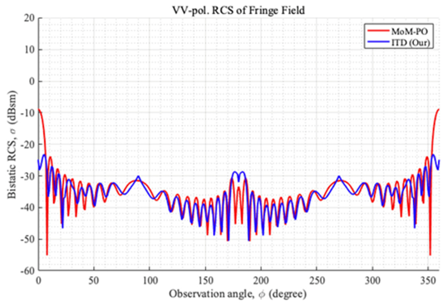
Fig. 5 presents the VV-pol. bistatic fringe field from the impedance surface of the triangular impedance cylinder with respect to θ = 90° and φ = 0°–360° for an incident plane wave of θ’ = 45° and φ’ = 0°. Notably, since the observation points are located outside the diffraction cone, the fringe field in Fig. 5 displays a lower level than that in Fig. 3. In addition, since both the side and top wedges contribute to the fringe field in Fig. 4, its pattern differs substantially from that in Fig. 3. Overall, while the results of the proposed ITD formula and MoM–PO maintained a relatively similar level, the results of the VIRAF ITD solver displayed patterns that were substantially different—even unsymmetrical—from those of the MoM–PO.

VV-pol. bistatic RCS of the fringe field from a triangular impedance cylinder illuminated by a planewave with θ’ = 45° and φ’= 0°: MoM-PO (red line), ITD (blue line), and ITDVIRAF (green line).
The fringe fields from the thin disk illuminated by a normally incident planewave are shown in Fig. 6. It is evident that, in the case of most observation angles, the proposed ITD formula maintains a similar pattern and level as the MoM–PO. This indicates that the proposed formula renders an accurate fringe field for a curved half-plane, which is a non-canonical wedge. However, there are spiky patterns at φ = 90° and 270°, parallel to the disk plane, as well as some discrepancies between the results of the proposed ITD and the MoM–PO at φ = 0° and 180°, which correspond to the front and back directions, respectively. Furthermore, when the observation point is located in front of the disk, the error in the fringe field does not have a significant effect on the total scattered field due to the strong reflected field.
VV-pol. bistatic RCS of the fringe field from a disk illuminated by a planewave with θ’ = 90° and φ’= 0°: MoM-PO (red line) and the proposed ITD (blue line).
Similar to the triangular impedance cylinder model, the scattered field generated by the disk model was obtained by summing the fringe field and the PO field, after which it was plotted along with the scattered field of the MoM, as shown in Fig. 7. It is observed that the proposed ITD solution maintains a very close agreement with the bistatic RCS of the MoM.

VV-pol. bistatic RCS of the scattered field from a disk illuminated by a planewave with θ’ = 90° and φ’= 0°: MoM (red line) and the proposed ITD (blue line).
IV. Conclusion
This study introduced a novel heuristic ITD formula to estimate the fringe field generated by an impedance surface wedge with an arbitrary exterior angle. Notably, the original ITD formula for a PEC wedge was derived from the Fourier transform pair relationship between the solution for the canonical wedge problem and the incremental field contribution. However, this study drew on the relationship between the ITD and the UTD pertaining to a PEC wedge to simply derive the heuristic ITD from the UTD diffraction coefficient of a wedge with impedance surfaces. In other words, this study expanded the normal incidence of the impedance wedge to achieve oblique incidence in the same way as the normal incidence of a PEC wedge can be extended to attain oblique incidence. In particular, the incremental PO edge-diffracted field was conceptually derived from the ISB- and RSB-related terms of the incremental diffracted field.
Furthermore, this study presented the numerical obtained on implementing the proposed ITD formula on a triangular impedance cylinder and a circular disk, and compared them with those of an MoM and VIRAF’s ITD solver. Although the results of the proposed ITD did not completely match those of the MoM, since it did not account for the effects of surface fields, it provided more accurate results than VIRAF’s ITD solver.
Future research must focus on introducing further improvements to the ITD formula by accurately calculating the incremental PO edge-diffracted field and accounting for the surface waves.
Acknowledgments
This work was supported by the Agency for Defense Development Grant, funded by the Korean Government (No. UD210001FD).
References
Biography

Jun-Seon Kim, https://orcid.org/0000-0002-2102-6264 received his B.S. and M.S. degrees in radio communication engineering from Korea Maritime and Ocean University (KMOU), Busan, South Korea, in 2022 and 2024, respectively. He is currently working toward his Ph.D. degree at the same university. His research interests include numerical techniques in the areas of electromagnetics and radar cross-section analysis.

Hyun-Soo Lee, https://orcid.org/0000-0003-0999-6126 received his B.S., M.S., and Ph.D. degrees from Inha University, Incheon, South Korea in 2012, 2014, and 2019, respectively. In 2019, he joined the Agency for Defense Development (ADD), Daejeon, South Korea, where he is currently a senior researcher. His current research interests include numerical and analytical methods for electromagnetic fields.

Jong-Eon Park, https://orcid.org/0000-0002-6357-2634 received his B.S., M.S., and Ph.D. degrees from the School of Electrical Engineering and Computer Science at Kyungpook National University, Daegu, Korea, in 2006, 2009, and 2013, respectively. From 2013 to 2015, he served as a post-doctoral researcher at Ohio State University. Following this, he held the position of research professor at Hongik University from 2016 to 2019. In 2020, he worked as an assistant professor at Dongguk University. Since 2021, he has been affiliated with Korea Maritime & Ocean University, where he currently serves as an assistant professor in the Division of Navigation Convergence Studies. His research interests include scattering through apertures, antenna design, computational electromagnetics, electromagnetic compatibility, and related areas.

Dong-Wook Seo, https://orcid.org/0000-0001-9449-7772 received his B.S. degree in electrical engineering from Kyungpook National University, Daegu, South Korea, in 2003, and his M.S. and Ph.D. degrees in electrical engineering from Korea Advanced Institute of Science and Technology (KAIST), Daejeon, South Korea, in 2005 and 2011, respectively. He was a senior researcher at the Defense Agency for Technology and Quality (DTaQ), Daegu, from 2011 to 2012. From 2012 to 2017, he served as a senior researcher at the Electronics and Telecommunications Research Institute (ETRI), Daegu. Since September 2017, he has been a faculty member of the Division of Electronics and Electrical Information Engineering, Korea Maritime & Ocean University (KMOU), Busan, South Korea, where he is currently an associate professor. His current research interests include numerical techniques in the area of electromagnetics, radar cross-section analysis, wireless power transfer, and radar systems.