CRLH Leaky-Wave Antenna with High Gain and Wide Beam-Scanning Angle for 5G mmWave Applications
Article information

Abstract
In this paper, a novel composite right-/left-handed (CRLH) leaky-wave antenna with a simple structure, low cost, high gain, and wide beam-scanning range performance for the millimeter wave (mmWave) band. The proposed antenna comprises a series-fed array of asymmetrically slotted elliptical CRLH unit cells loaded with a short-circuit stub. By optimizing the length of the stub, the condition of the CRLH structure is balanced to enable beam scanning from the backward to the forward direction within the mmWave band. The proposed antenna exhibits a wide beam-scanning angle of 112° (−60° to 52°), coupled with high gain and radiation efficiency at the designated band. Furthermore, it is fabricated on a traditional microwave substrate, Rogers RT/duroid 5880, thus offering a cost-effective approach to streamlining the manufacturing process. The measurement results confirmed a peak realized gain of 16.8 dBi. The excellent performance achieved using a low-cost design makes the proposed antenna attractive for 5G mmWave applications.
I. Introduction
Millimeter waves (mmWave) ranging from 24 to 40 GHz are integral to fifth-generation (5G) communication systems, since they offer a significantly wider bandwidth compared to the currently used sub-6 GHz band. In other words, the use of the mmWave will enable the achievement of higher data rates and capacities. However, this frequency band is also well known for higher free-space path loss and increased atmospheric absorption [1], which limits the coverage of base stations and mobile equipment. To address this challenge, high-gain antennas, which necessitate beam-steering capabilities, have been proposed [1].
Characterized by advantageous properties such as high gain and structural simplicity without the need for a costly and complicated feed network, leaky-wave antennas (LWAs) are an economical alternative to phased array antennas for beam-steering applications. However, due to the open-stopband (OSB) effect, conventional LWAs encounter the problem of limited scanning range, since they either support only a forward wave or both backward and forward waves, but not broadside waves [2]. To acquire a full beam-scanning range and overcome the OSB effect, several types of microstrip LWAs have been proposed in the literature, including those employing asymmetric unit cells [3], reflection cancelation [4], and impedance matching [4]. Notably, the authors of [3] introduced a periodic microstrip LWA that achieved scanning radiation using a combination of two vias and two microstrip step discontinuities in a suitable structure. However, the beam-scanning angle achieved by this antenna was relatively narrow (95°). In addition, several LWAs have been developed based on radiation patches coupled with spoof surface plasmon polaritons, as in [5–7]. However, since these patches bear different shapes, the surface current direction on them changes significantly under the influence of frequency, resulting in radiation pattern deformation or a limited beam-scanning range [6].
Recently, composite right-/left-handed (CRLH) LWAs have been introduced to achieve a wide beam-scanning angle [8]. The CRLH LWA is a structure that combines conventional left-handed (LH) transmission lines, which are used as high-pass filters with phase-advanced (β < 0), with metamaterial-based right-handed (RH) transmission lines used as low-pass filters with phase-delay (β > 0). This combination allows the CRLH LWA to attain the unique advantage of backfire (lower frequencies–LH region) to endfire (higher frequencies–RH region) scanning capability [8]. In this context, various CRLH LWAs operating in the mmWave band have been developed based on different fabrication technologies [9–11]. For instance, Jiang et al. [9] demonstrated a microstrip LWA with CRLH behavior, which achieved a gain of 14 dBi and a scanning angle of 75° in the 20–30 GHz operating band. In [10] and [11], substrate-integrated waveguide (SIW) CRLH LWAs achieved beam-scanning angles of 60° and 30°, respectively. However, the achieved beam-scanning angle of these CRLH LWAs was narrow since its performance decreased with frequency, especially at mmWave frequencies. This decline can primarily be attributed to the distributed capacitance and inductance of the CRLH structures [11]. Moreover, most mmWave CRLH LWAs reported in the literature have been fabricated using either complex multilayer PCB technology or SIW, both of which require a multi-via structure, leading to increasing fabrication complexity and fabrication costs.
This paper addresses the abovementioned challenges by proposing a low-cost and high-gain CRLH LWA operating in the mmWave band that also features a wide beam-scanning angle. The unit cells of the proposed CRLH LWA bear a single-layer structure based on the low-cost Roger RT/duroid 5880 substrate. Furthermore, the patch and ground plane are connected using a single via, thus allowing for reduced complexity compared to the SIW approach. Overall, owing to the careful design and length optimization of the stub element combined with the use of a limited number of vias, the proposed linearly polarized antenna, exhibiting primary polarization in the vertical direction, achieves high gain, efficiency, and a wide beam-scanning angle using a moderate design and cost-effective fabrication process compared to the state of the art.
II. CRLH Leaky-Wave Antenna Structure
This section provides a brief description of the configurations of the proposed antenna, which was developed using a CRLH unit cell with respect to the scanning angle range and phase constant. Furthermore, it presents the results of the simulation performed to understand the behavior of the CRLH unit cell and its resolution of the OSB effect. In addition, the findings of a general analysis of the circuit model equipped with a stub element parameter to achieve a balanced condition (i.e., LRCL = LLCR), which was conducted without affecting the elliptical antenna structure, are reported.
1. Antenna Configuration
Fig. 1 presents the configuration of the proposed CRLH LWA prototype. As shown in Fig. 1(a), the antenna is a microstrip transmission line structure bearing a periodic configuration. It is composed of 15 periods (unit cells), with port 1 and port 2 matched with a 50 Ω microstrip line. The configurations of the unit cell are presented in Fig. 1(b) and 1(c). Notably, the antenna was designed and built on a single-layer PCB based on the traditional Rogers RT/duroid 5880 substrate with a loss tangent (tanδ) of 0.0009, permittivity (ɛr) of 2.2, and thickness (h) of 0.254 mm. Furthermore, the top and bottom layers, made of copper, were connected using a via Fig. 1(b).
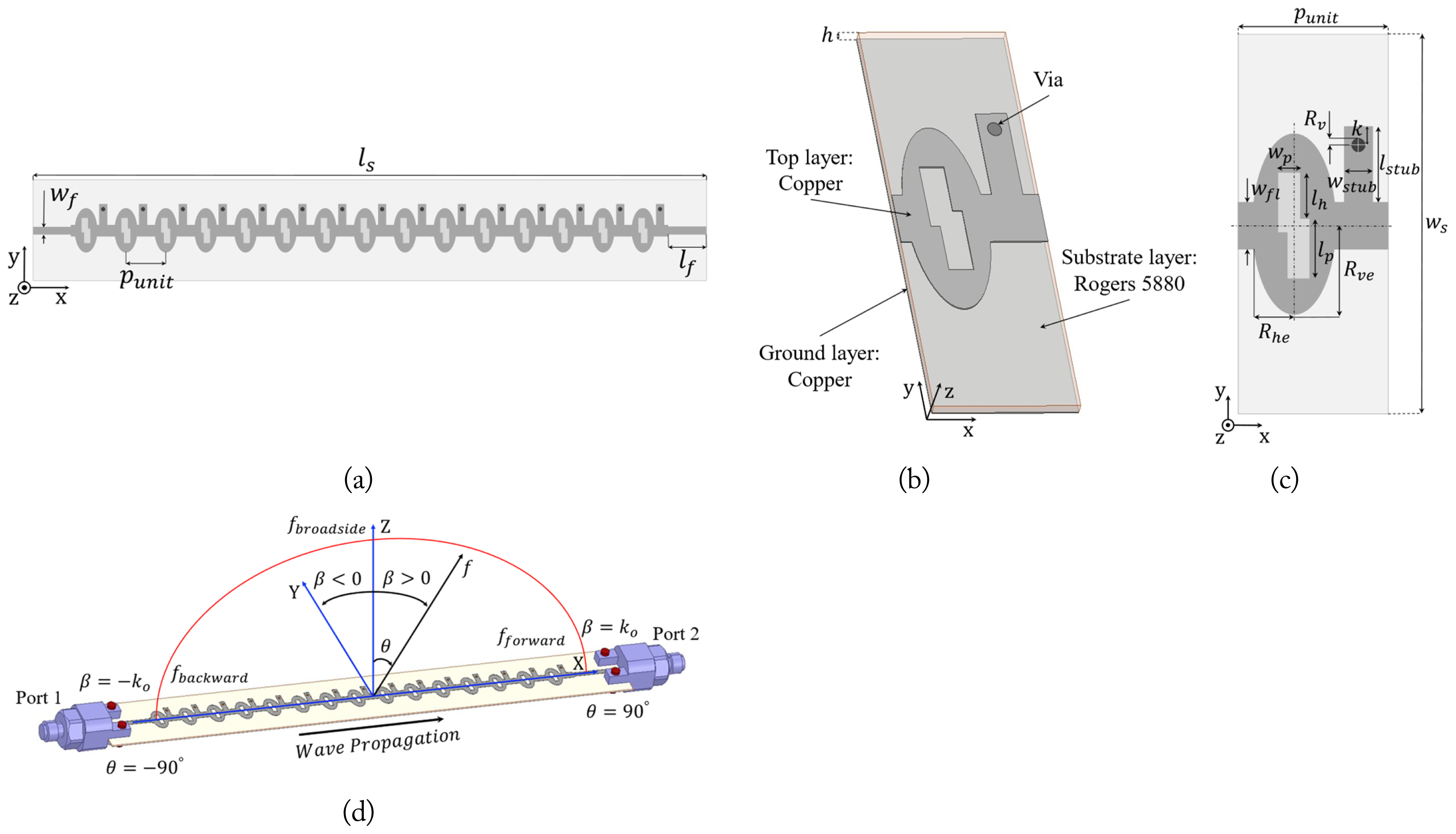
(a) Top view of the proposed antenna consisting of 15 unit cells, (b) 3D view, (c) top view of the unit cell with its dimensions, and (d) illustration of the working mechanism of the proposed CRLH LWA. The optimized parameter values (unit: mm) are punit = 5, ws = 12 wfl = 1.5, Rve = 2.9, Rhe = 1.3, lh = 1.4, wp = 0.8, lp = 1.9, k = 0.5, Rv = 0.23, wstub = 1, lstub = 2.6, wf = 0.8, h = 0.254, lf = 15, and ls = 105.
Fig. 1(d) illustrates the working mechanism of the proposed antenna for achieving a wide beam-scanning angle. It is well known that an LWA bears the radiation angle of the main beam (θ)—a function that depends on the operating frequency (f)— which can be determined from the wave number (k0) and phase constant (β) using Eq. (1) [8]:
Eq. (1) shows that, in principle, full range scanning from −90° to 90° can be achieved if β varies from −k0 to k0, respectively, throughout the range. Therefore, based on the CRLH structure, the proposed antenna should be able to achieve a full range of β, supporting both backward and forward beam-scanning, as observed in Fig. 1(d).
2. Analysis of Backward-to-Forward Radiation of the CRLH Unit Cell
The phase constant of the CRLH unit cell configuration for the n-th space harmonic can be expressed as follows:
where n = 0,±1,±2,… represents the ordinal of the space harmonics and β0 refers to the phase constant of the fundamental space harmonic (n = 0).
Using Eq. (2), the phase constant of the space harmonics is plotted with regard to the frequency, as shown in Fig. 2. The highlighted region represents the fast wave region from 20 to 40 GHz, which was determined under the condition of −k0≤ β≤k0. Point A (fc1 = 22.5 GHz), where the first radiating mode (β−1) intersects the boundary of the fast wave zone, represents the backward radiation, which crosses the broadside radiation at point B (fc = 31 GHz) to become forward radiation.

Brillion diagram of the CRLH unit cell.
Meanwhile, the second radiating mode (β−2) line crosses the boundary of the fast wave zone at point C (fc2 = 38 GHz) as backward radiation. This indicates that at a frequency band higher than 38 GHz, two radiation modes (β−1 and β−2) operate simultaneously, but in two different directions. Thus, to address this undesirable issue for single beam scanning, a frequency range from 22.5 to 38 GHz is considered, where the unit cell achieves the best single-mode scanning.
Fig. 3(a) shows the input impedance of the proposed unit cell in the 22–40 GHz frequency range. While the imagined impedance value reaches zero, the real impedance peaks at the broadside frequency of 31 GHz, indicating suspension of the OSB effect. Hence, the antenna radiates at that frequency [4]. Furthermore, the surface current on the top layer of the unit cell at 31 GHz was extracted, as shown in Fig. 3(b). The currents at the input and output of the unit cell move in the same direction, showing that they are in phase with each other, which means that the phase difference between them is zero. This result reconfirms the conclusion that the OSB effect is perfectly addressed at a frequency of 31 GHz [12].
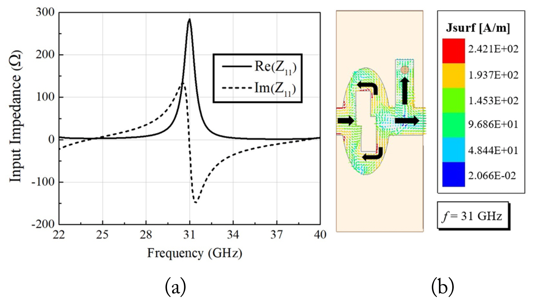
(a) Input impedance of the unit cell and (b) surface current vector at 31 GHz.
3. Circuit Model Analysis and Parametric Study
The equivalent circuit analysis model for one unit cell is presented in Fig 4(a). To obtain a CRLH-balanced condition (i.e., LRCL = LLCR), the series capacitor is placed at the center of the model as CL, creating a slot in the structure, while the shunt inductance constructed by the via element is denoted by LL. These components represent the LH behavior of the CRLH structure. Meanwhile, the series inductance LR (LR = LR1 + LR2), arising from the outer patch (LR1) and the stub element (LR2 ), and shunt capacitance CR, indicating the capacitance generated between the top and ground layers, comprise the RH contribution. The phase constant of the CRLH model is obtained from the synthesis of the positive RH mode and the negative LH mode, as shown in Eq. (3) [9]:
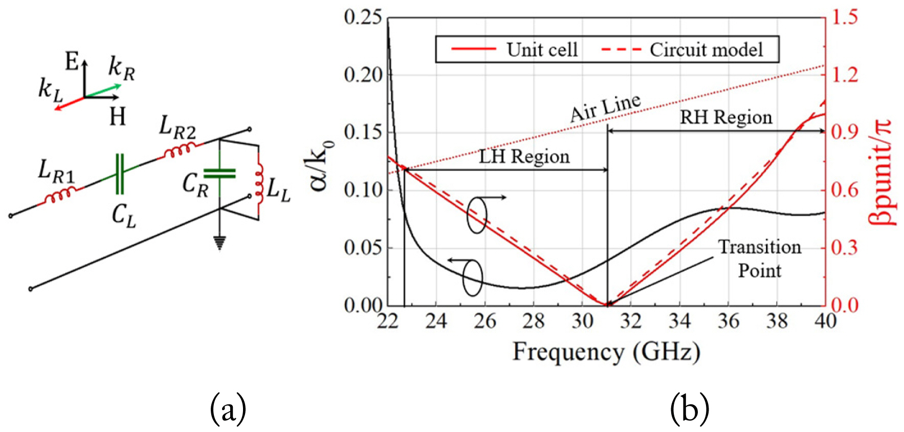
(a) Equivalent circuit analysis model and (b) dispersion (β) and attenuation (α) curves for the CRLH structure. Circuit parameters are LR1 = 0.25 nH, LR2 = 0.21 nH, CL = 0.057 pF, CR = 1.3 pF, and LL = 0.02 nH.
where punit is the periodicity of the unit cell.
Furthermore, the values of the lumped elements in Fig. 4(a) were initially calculated using the microstrip line parameters detailed in [13]. In addition, with regard to the context of the current study, the CR value was analyzed based on the capacitance from the elliptical patch element (CR_patch) and the stub element (CR_stub), as shown in Eqs. (4)–(6):
Due to the approximate nature of the calculated values, particularly for the elliptical patch with a slot, a minor readjustment was made to match the calculated dispersion diagram with the Ansys HFSS simulation.
The optimized values of the lumped elements comprising the equivalent circuit (Fig. 4(a)) are provided in the caption for Fig. 4. As shown in Fig. 4(b), the simulated and calculated phase constants are well matched, confirming that the antenna acts as an LH structure in the lower band and as an RH structure in the higher band. Moreover, the attenuation coefficient (α) of the CRLH structure exhibits low values in both the LH and RH regions.
As mentioned earlier, the LR2 and part of the CR (CR_stub) were tuned by the length of the stub element (lstub). The propensity of the normalized simulated phase (β−1/k0) and leakage constants (α/k0) of the proposed unit cell was examined by changing the lstub value without affecting the elliptical patch configuration, as depicted in Fig. 5(a). The normalized phase constant values tend to shift toward the low-frequency region as the lstub values increase, while the leakage constant values are more attenuated in the high-frequency region. Simultaneously, the radiation pattern deviates from the broadside position, as depicted in Fig. 5(b). It is evident that the lstub effectively controls the leakage constant and avoids the OSB effect at a frequency of 31 GHz.

Normalized simulated (a) phase (β−1/k0) and leakage (α/k0) constants of the unit cell, and (b) radiation patterns of the proposed structures at the broadside frequency for various lengths of the stub element (lstub).
As a result, the normalized phase constant remains undisturbed, displaying a seamless backward to forward transmission, with the highest gain at the broadside frequency achieved at lstub = 2.6 mm (≈ 0.4 λg at 31 GHz).
III. Measurement Results and Discussion
This section demonstrates the fabrication process of the proposed CRLH LWA and presents the results of the far-field measurements carried out to verify its performance and confirm its potential for use in 5G mmWave applications. Fig. 6(a) shows the far-field measurement setup in an anechoic chamber equipped with standard horn antennas from Millitech Inc. (SGH-42 and SGH-28) having 24 dBi peak gain, which were used as transmitting (Tx) antennas, while the antenna under test (AUT) acted as the receiving (Rx) antenna. Fig. 6(b) presents a photograph of the fabricated CRLH-LWA prototype.

Photograph of (a) the AUT in a microwave anechoic chamber and (b) the fabricated CRLH-LWA prototype.
Fig. 7(a) shows that the S-parameter of the AUT, measured using an Agilent Technologies E8364B network analyzer, matches well with that of the simulation results. The measured S11 < −10 dB and S21 < −7.5 dB were achieved in the 24–40 GHz frequency band. Notably, the minor variations observed may be attributed to the precision of the fabricated antenna process, the unstable test fixed connection, and the unpredictable test environment, which could have affected the accuracy of the results obtained in the radiation performance measurement.

(a) Simulated and measured results of S11 sand S21, and (b) antenna gain, cross-polarization levels, and simulated radiation efficiency of the proposed CRLH-LWA.
Fig. 7(b) presents the measured gain and cross-polarization levels of the proposed AUT, both of which are observed to be relatively compatible with those of the simulated one. A measured peak gain of 16.8 dBi and a simulated radiation efficiency above 78% is achieved in the concerned bandwidth. Moreover, the experimental values of the cross-polarization levels are below 20 dB, demonstrating that the antenna performance would not be significantly affected by mutual coupling between polarization ports.
Fig. 8 illustrates the simulation and measurement results of the radiation patterns at various frequencies. As expected, the radiating beam of the AUT moves from the backward direction when the frequency band is below 31 GHz toward the forward direction when the operating frequency increases above 31 GHz. This confirms that the radiation pattern belongs to the LH region in the lower band and the RH region in the higher band. The beam-scanning angle of the AUT ranges from −60° at 24 GHz to 52° at 40 GHz, demonstrating a wide range of 112°. In this context, it is also worth noting that at frequencies above 38 GHz, the two modes operated simultaneously but in two different directions, as mentioned above, as a result of which the dual beam could not be clearly formed [14]. This explains the significant drop in gain observed at 40 GHz in Fig. 8.
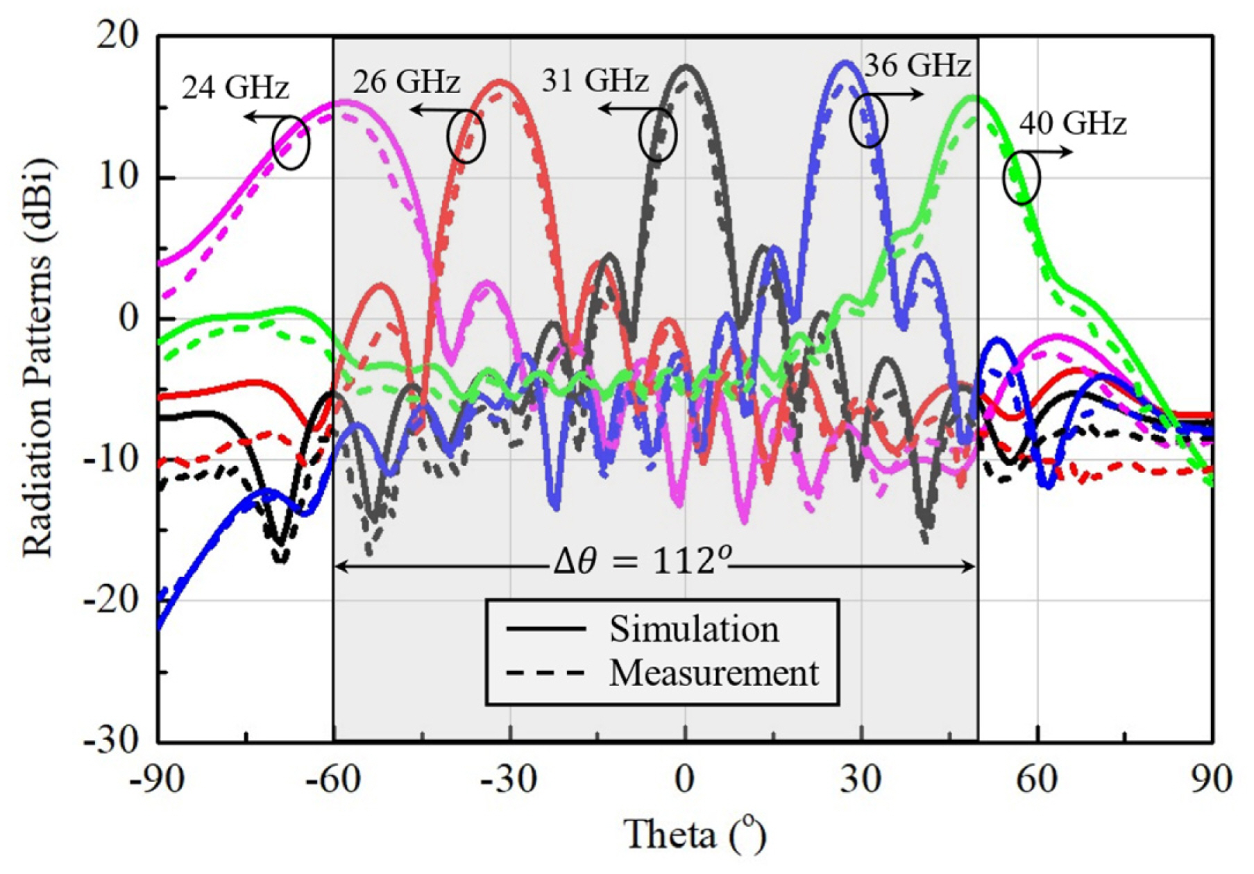
Simulation and measurement results of the radiation patterns of the antenna at various frequencies.
To examine the features of the proposed antenna, an antenna performance comparison was conducted, as listed in Table 1. When comparing the dimensions, performance, and complexity of the proposed antenna with those of existing mmWave LWAs, it is observed that the beam-scanning angle range achieved by the proposed antenna is the widest. Moreover, the proposed antenna shows good performance in terms of gain and efficiency. Regarding dimensions and complexity, the proposed antenna possesses a relatively compact size and a simple structure characterized by a single layer of low-cost PCB and a minimum number of vias.

Performance comparison of the proposed antenna with other mmWave LWAs
IV. Conclusion
This study proposes a novel low-cost CRLH LWA with a simple structure that yields high gain, broadband, and a wide beam-scanning angle range for 5G mmWave applications. Notably, the equivalent circuit method is used to theoretically predict the behavior of the antenna. The simulation and measurement results exhibit good agreement with the theoretical calculations, with a gain of more than 14.2 dBi and radiation efficiency above 78% obtained in a wide operating band ranging from 24 to 40 GHz. Moreover, owing to the nature of LWAs, the proposed antenna is characterized by low fabrication complexity, a wide beam-scanning range of 112°, and ease of integration with other microwave circuits, making it highly attractive for 5G mmWave applications.
Acknowledgments
This study was supported by the Research Program funded by the Seoul National University of Science and Technology.
References
Biography

Nguyen Tien Thinh, https://orcid.org/0000-0002-3166-1501 received his B.S. degree in electronics and telecommunications engineering from Hanoi University of Science and Technology (HUST), Vietnam, in 2021, and his M.S. degree in electrical engineering from the Seoul National University of Science and Technology, Seoul, South Korea, in 2023. He is currently an antenna engineer at Viettel High Tech (VHT), Hanoi, Vietnam. His current research interests include sub-THz antennas, frequency-selective surfaces, millimeter-wave applications, reflect/transmit-array antennas, and reconfigurable intelligent surfaces (RIS).

Phan Duy Tung, https://orcid.org/0000-0003-1783-2519 received his M.S. degree in radio engineering from Tula State University, Tula, Russia, in 2015, and his D.Sc. degree in nano IT fusion engineering from the Seoul National University of Science and Technology, Seoul, South Korea, in 2021. From 2015 to 2018, he served as a lecturer in the School of Engineering and Technology at Vinh University, Vietnam. Since September 2021, he has been a post-doctoral research fellow at the Centre for Wireless Communications, University of Oulu, Oulu, Finland. His research interests include antenna design and application in next-generation communications, electromagnetic wave manipulation through reconfigurable intelligent surfaces and its application in communications and sensing, and electromagnetic compatibility.

Chang Won Jung, https://orcid.org/0000-0002-8030-8093 received his B.S. degree in radio science and engineering from Kwangwoon University, Seoul, South Korea, in 1997, and his M.S. degree in electrical engineering from the University of Southern California, Los Angeles, CA, USA, in 2001. In 2005, he received his Ph.D. in electrical engineering and computer science from the University of California at Irvine, Irvine, CA, USA. He was a research engineer at the Wireless Communication Department of LG Information and Telecommunication, Seoul, South Korea, from 1997 to 1999. From 2005 to 2008, he was a senior research engineer at the Communication Laboratory, Samsung Advanced Institute of Technology, Suwon, South Korea. In 2008, he joined the Graduate School of Nano-IT Design Technology as a professor. Since 2022, he has been serving as a professor in the Department of Semiconductor Engineering at Seoul National University of Science and Technology, Seoul, Korea. His current research interests include antennas for multi-mode multi-band communication systems, multifunctional reconfigurable antennas, electromagnetic interference, millimeter-wave applications, optically transparent electrodes, and wireless power transfer for energy harvesting.