I. INTRODUCTION
With the rapid development of mobile communication technology, compact miniaturized antennas are currently being used in a wide range of applications. In particular, the development of 5G telecommunication systems for mobile handsets has massively increased the demand for high data quality and data transfer rates. As a result, designing antennas that support wide band requirements, even when the technology is miniaturized, has emerged as a challenge [1ŌĆō4].
To address this issue, multiple-input and multiple-output (MIMO) antenna systems that can transmit and receive signals are being used globally. Notably, these systems can be of great use in 5G MIMO communications. Today, the integration of more antennas into communication terminals has become a mega-trend. In this regard, the MIMO antenna offers the advantages of improved space utilization and increased coverage of wireless systems [5]. Specifically, in the context of the sub-6 GHz band, the 3.5 GHz (3.4ŌĆō3.6 GHz) and New Radio (NR) operating bands within the FR1 band have attracted a wide range of applications for 5G wireless communication in recent years [6, 7]. In this context, while the characteristic mode theory was revised by Garbacz in 1968, the theory of characteristic modes for conducting bodies was revised by Harrington and Mautz in 1971 [8]. This concept has greatly affected MIMO antenna design that is aimed at improving correlation performance and isolation between antennas [9ŌĆō13]. Consequently, developing a compact and efficient MIMO antenna was found to be the primary focus of many studies. However, in previous studies [14, 15], the antenna clearance regions (more than 10 mm ├Ś 10 mm) took up a significant amount of physical space on the printed circuit board (PCB), making the process of antenna miniaturization difficult. Nonetheless, ground-radiation antennas using small clearance technology have already been applied in many devices [16ŌĆō19]. In this paper, the researchers combined the proposed antenna feed structure with ground radiation technology designed for 5G terminal equipment.
Specifically, this paper proposes a 4 ├Ś 4 MIMO antenna based on the concept of the characteristic mode for 5G terminals [12]. The proposed feeding structure includes a series capacitor and a parallel capacitor to control the antenna input impedance matching for the proposed MIMO antenna system. Furthermore, a resonance loop capacitor is employed to control the resonance frequency of the proposed antenna. Moreover, an antenna using ground radiation to achieve wide-band technology was designed. The proposed antenna attained a ŌłÆ6 dB bandwidth of 1,240 MHz, ranging from 3.14 GHz to 4.38 GHz, in the simulation, while the measurement results showed a satisfactory performance of 1,380 MHz for a ŌłÆ6 dB bandwidth, with frequencies ranging from 3.12 GHz to 4.50 GHz. Additionally, the average efficiency increased from 38.7% (reference) to 49.1% (proposed) in the 3 GHzŌĆō4.6 GHz range. The target frequency of the proposed technology was 3.3 GHz to 4.2 GHz, meaning that it could operate in the 5G NR n48 (3,550ŌĆō3,700 MHz), n77 (3,300ŌĆō4,200 MHz), and n78 (3,300ŌĆō3,800 MHz) platforms. These results indicate that the proposed technology has good application prospects for 5G communication terminal antenna designs.
II. ANTENNA DESIGN AND CHARACTERISTIC MODE ANALYSIS
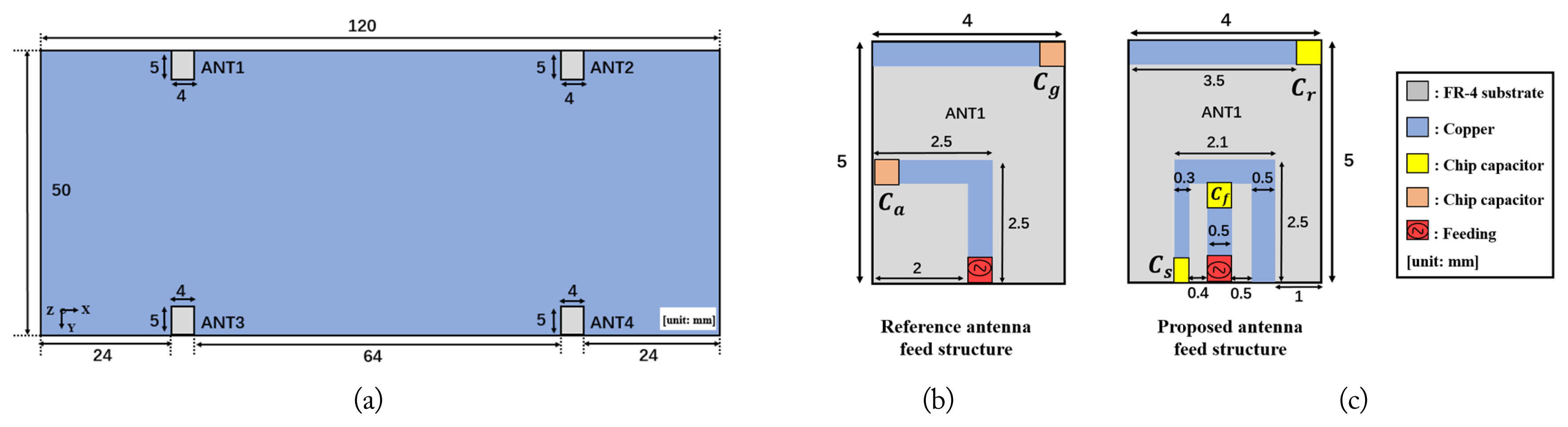
The proposed 4 ├Ś 4 MIMO antenna system for the 3ŌĆō4.5 GHz frequency range with n48, n77, and n78 applications is depicted in Fig. 1. The 50 mm ├Ś 120 mm ├Ś 1 mm ground plane is printed on an FR4 (frame retardant type 4) substrate with a dielectric constant of ╔ør = 4.4. Each proposed antenna, with a ground clearance of 5 mm ├Ś 4 mm, is identical, mirror-symmetric, and located 24 mm from the edge on top of the PCB.
This study considers a traditional ground-radiation antenna as the reference antenna, where the magnetic flux produced by a loop-type current around the clearance, which is the resonance frequency, was determined by the chip capacitor Cg. Meanwhile, the input impedance matching in the reference antenna was determined by the chip capacitor Ca, as shown in Fig. 1(b) [16ŌĆō19]. For comparison purposes, a voltage source was added for the excitation of the reference antenna while a series capacitor Cg (0.15 pF), which adjusted its resonance frequency when excited by a 2.5 mm ├Ś 2.5 mm feeding loop [16ŌĆō19], was added in series with capacitor Ca (0.35 pF) for impedance matching, as shown in Fig. 1(b). The edge-to-edge separation between ANT1 and ANT2, as well as between ANT3 and ANT4, is 64 mm (0.87╬╗).
Meanwhile, the proposed antenna was designed on a 5 mm ├Ś 4 mm clearance of the ground plane. Furthermore, a resonance capacitor Cr (0.15 pF) was added at the end of the clearance to control the antennaŌĆÖs resonance frequency. A 2.5 mm ├Ś 2.1 mm feeding structure was employed for the proposed antenna, equipped with a series capacitor Cf (0.51 pF) and a parallel capacitor Cs (0.38 pF) to achieve input impedance matching, as shown in Fig. 1(c) [20]. Moreover, the proposed antenna had a different feeding structure than the traditional ground-radiation antenna. In this context, it should be noted that the conductor line widths for both the reference and proposed MIMO antennas were 0.5 mm. It is also worth noting that the proposed MIMO technology can be applied to different situations as well, including for the purpose of accommodating various sizes and modules of the evaluation board and for different size changes in feed structures.
III. SIMULATION RESULTS AND OPERATION MECHANISM
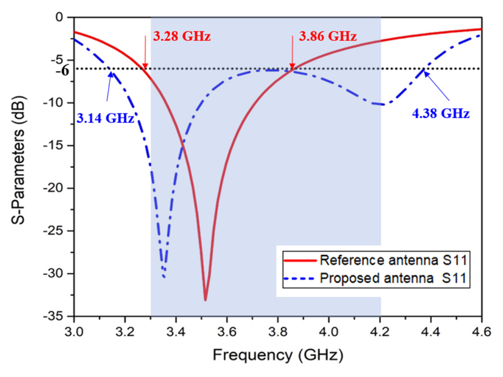
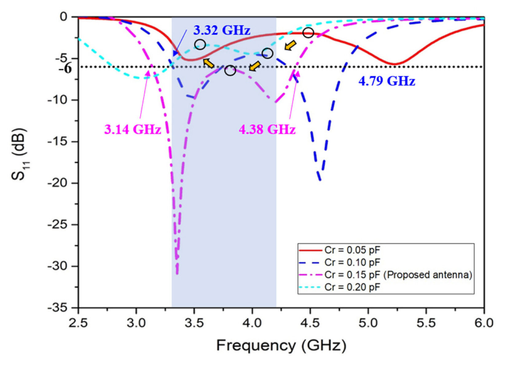
The simulation results obtained for the scattering parameters (S-parameters) of the reference and proposed MIMO antennas are presented in Fig. 2. The ŌłÆ6 dB bandwidth corresponds to the voltage stand wave ratio (VSWR) of 3, which is widely used, although a VSWR of 2 (ŌłÆ9.54 dB bandwidth) is also used in some cases [21, 22]. Fig. 2 shows that a ŌłÆ6 dB bandwidth of 600 MHz (ranging from 3.27 GHz to 3.87 GHz) was achieved by reference ANT1, while the proposed ANT1 attained a ŌłÆ6 dB bandwidth of 1,240 MHz (ranging from 3.14 GHz to 4.38 GHz), which covers the target frequency band (from 3.3 GHz to 4.2 GHz) for 5G applications entirely. Fig. 3 shows the simulated proposed antenna S11 values along with variations in the capacitor Cr values to illustrate the operation principle of the proposed antenna using ground radiation. It is evident that the central resonance frequency decreases as the capacitor Cr increases to 0.2 pF (Cf = 0.51 pF, Cs = 0.38 pF remained unchanged). This effect can be attributed to the inductance between the transmission line and ground plane, with the loaded capacitor Cr forming a loop-type resonance circuit using ground radiation [23]. This indicates that with an increase in the capacitance of Cr, the loop resonance frequency decreases. Furthermore, the inductance increases along with an increase in antenna clearance, causing the resonance frequency to decrease.
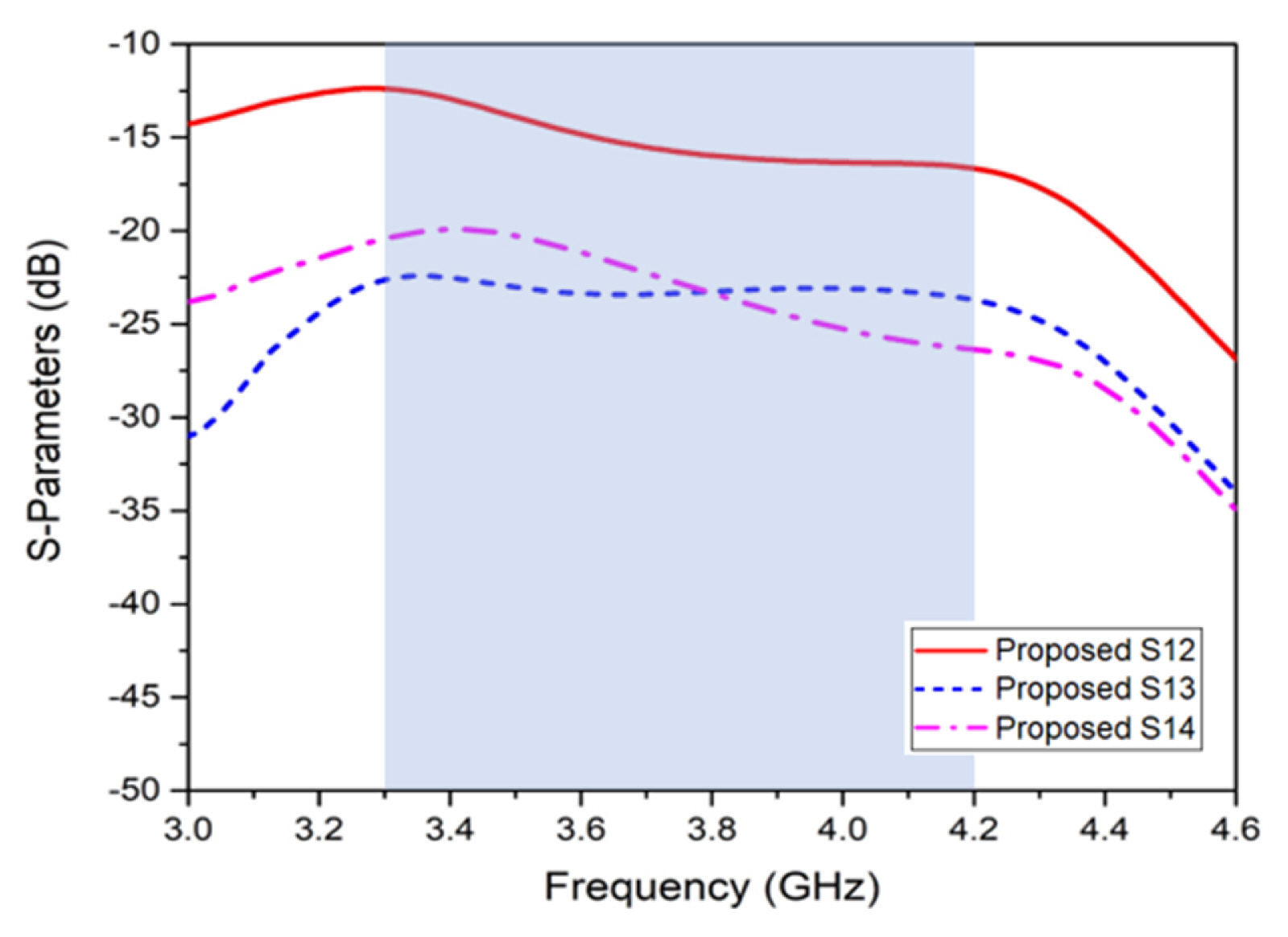
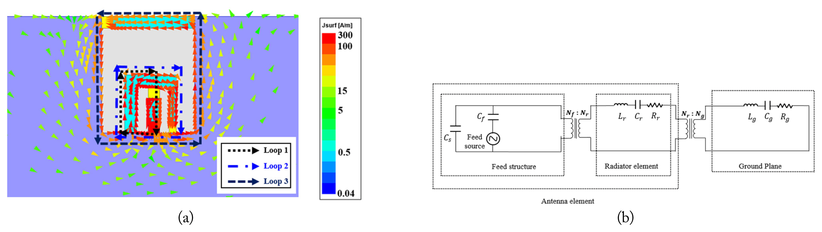
Therefore, the resonance frequency can not only be controlled by adjusting the capacitor value, but also by changing the clearance area. The simulated S-parameters of isolation for ANT1 to ANT4 are shown in Fig. 4, where it can be observed that the mutual coupling S12 between the proposed ANT1 and ANT2 is lower than ŌłÆ12.4 dB over the target frequency band. Meanwhile, for the other antennas, mutual coupling S13 and S14 is lower than ŌłÆ22.4 dB and ŌłÆ19.9 dB, respectively, over the target frequency band. To conduct a better interpretation of the operation mechanism of the proposed 4 ├Ś 4 MIMO antenna system, the simulated surface current distribution at 3.5 GHz for ANT1 is shown in Fig. 5(a), which clearly exhibits the operating current modes. Two loop currents are found in the feeding structure, denoted as Loop 1 and Loop 2, which can be represented by a two-pot impedance [Z] matrix [24], as follows:
where LLoop1 and LLoop2 refer to the inductances of Loop 1 and Loop 2 in the feeding structure, respectively. The ground plane was modeled as a series RLC circuit consisting of Rg, Lg, and Cg as a circuit model for the antenna elements, as shown in Fig. 5(b). The circuit between the ground plane and the proposed antenna impedance matching, using Z11, Z12, and Z22 in the two-port network, can be expressed as follows [19]:
In Eqs. (2)ŌĆō(5), Z11 denotes the feed structure network input impedance, Z12 refers to the mutual input impedance between the feed structure and the ground plane, and Z12 is the input impedance of both the outside resonance loop and the ground plane. Furthermore, Lfeed indicates the inductance, with the feed structure including LLoop1 and LLoop2, while Rr and Lr are the resistance and inductance of the outside resonance loop.
In conclusion, the proposed antenna is a small loop-type antenna forming a dipole-type radiator that can excite the ground plane [25]. According to the reaction concept and the characteristic modes theory of conducting bodies, the coupling between the ground plane and the proposed antenna can be expressed using the modal excitation coefficient [24] as follows:
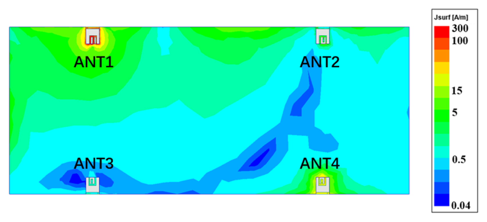
where Ēg and H̄g are the electric fields and magnetic fields generated from the ground plane with characteristic modes, and P̄p and M̄p are the electric currents and magnetic currents produced by the antenna in Eqs. (6) and (7). The loop-type current mode M̄p can react with the ground plane characteristic magnetic field H̄g. The total current J̄ on the ground plane can be expressed by Eq. (8), where λn is the eigenvalue associated with J̄n, which is the nth characteristic current mode [8]. When λn is infinitely close to 0, the denominator term becomes smaller at the same time that the coupling performance maximizes. In this regime, the characteristic modes of the ground plane radiate effectively in resonance [12]. Consequently, the antenna is coupled with the characteristic mode of the ground plane, where a resonance close to the target operating frequency achieves better radiation performance. Fig. 6 shows the simulated surface current distribution at 3.5 GHz for the proposed MIMO antenna system with Port 1 excitation. ANT1 excites the PCB at 1.5 times the wavelength of the mode, ensuring good performance of the antenna [10].
IV. EXPERIMENTAL RESULTS
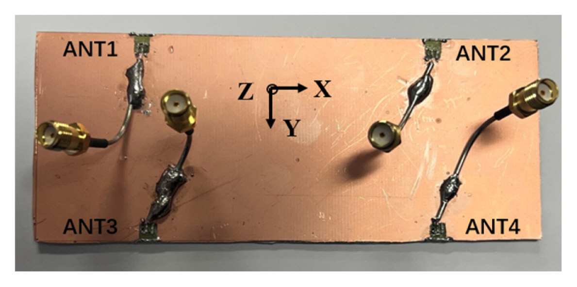
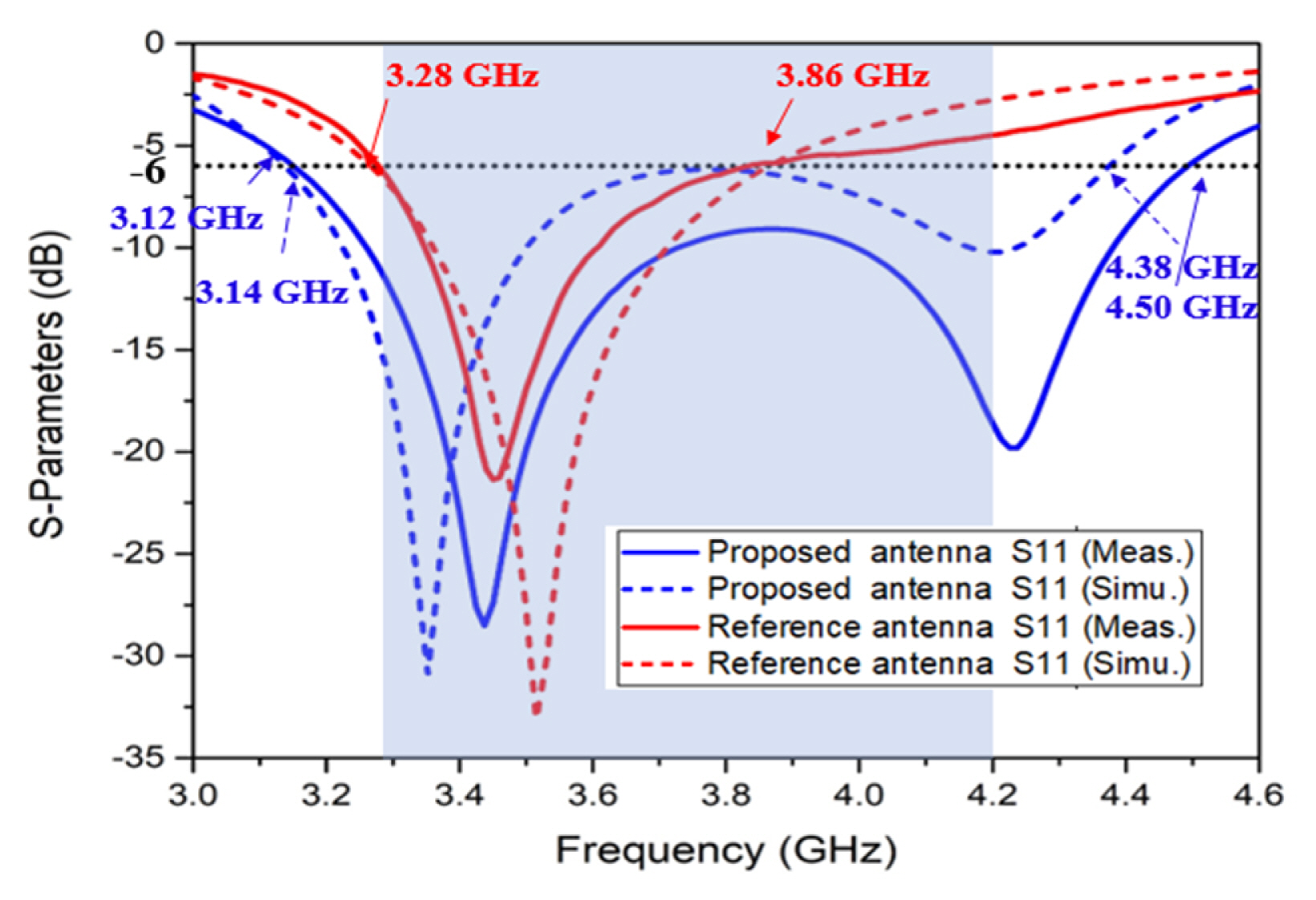
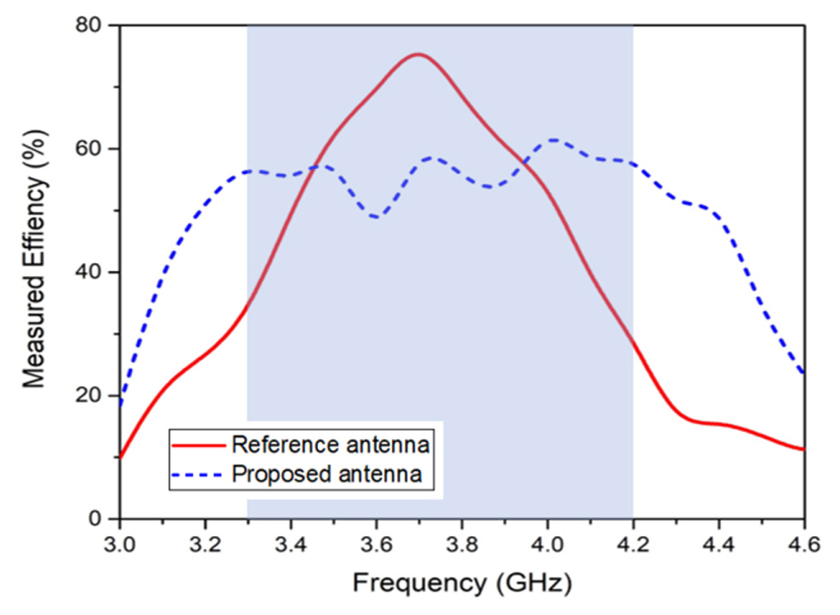
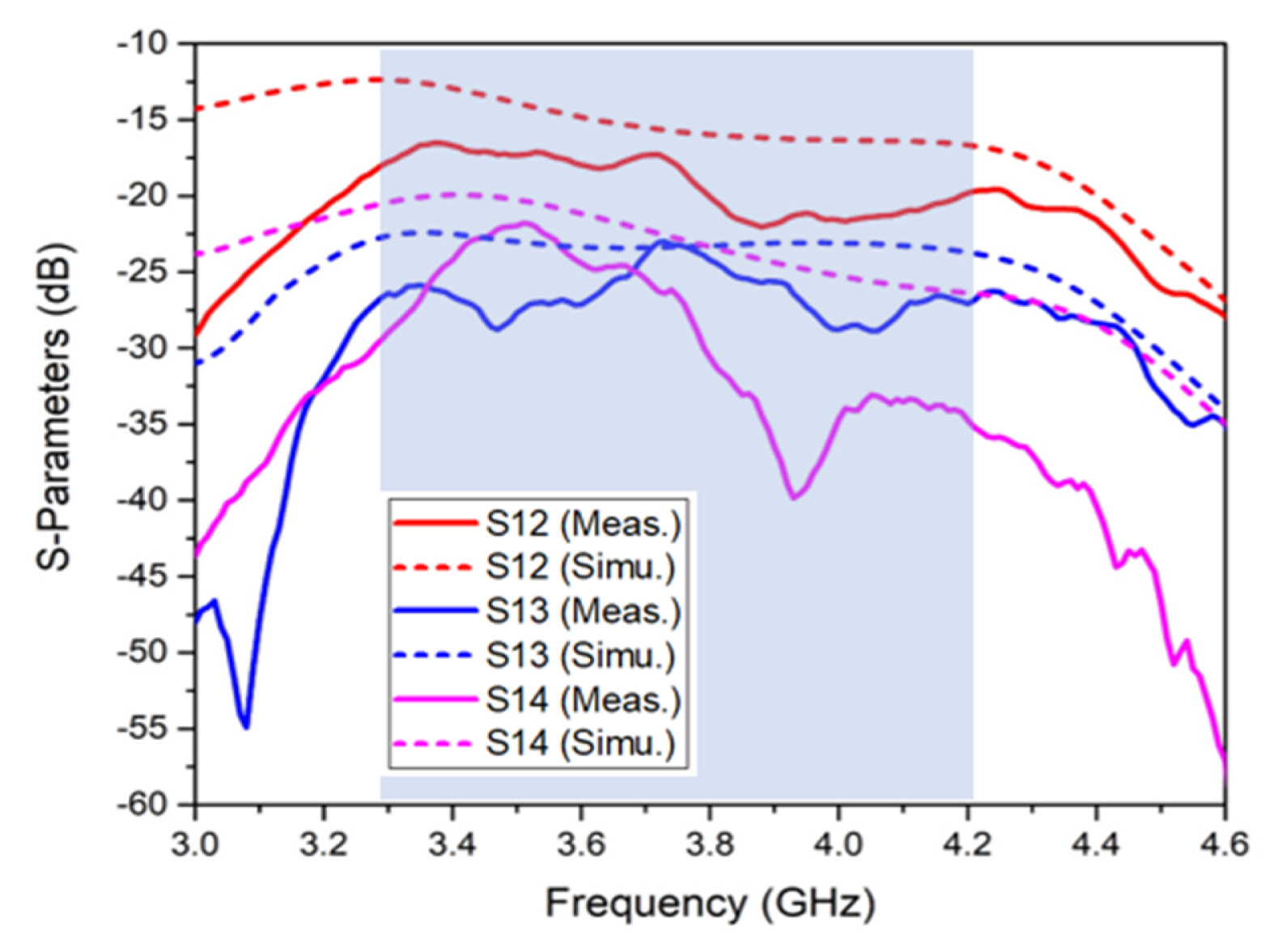
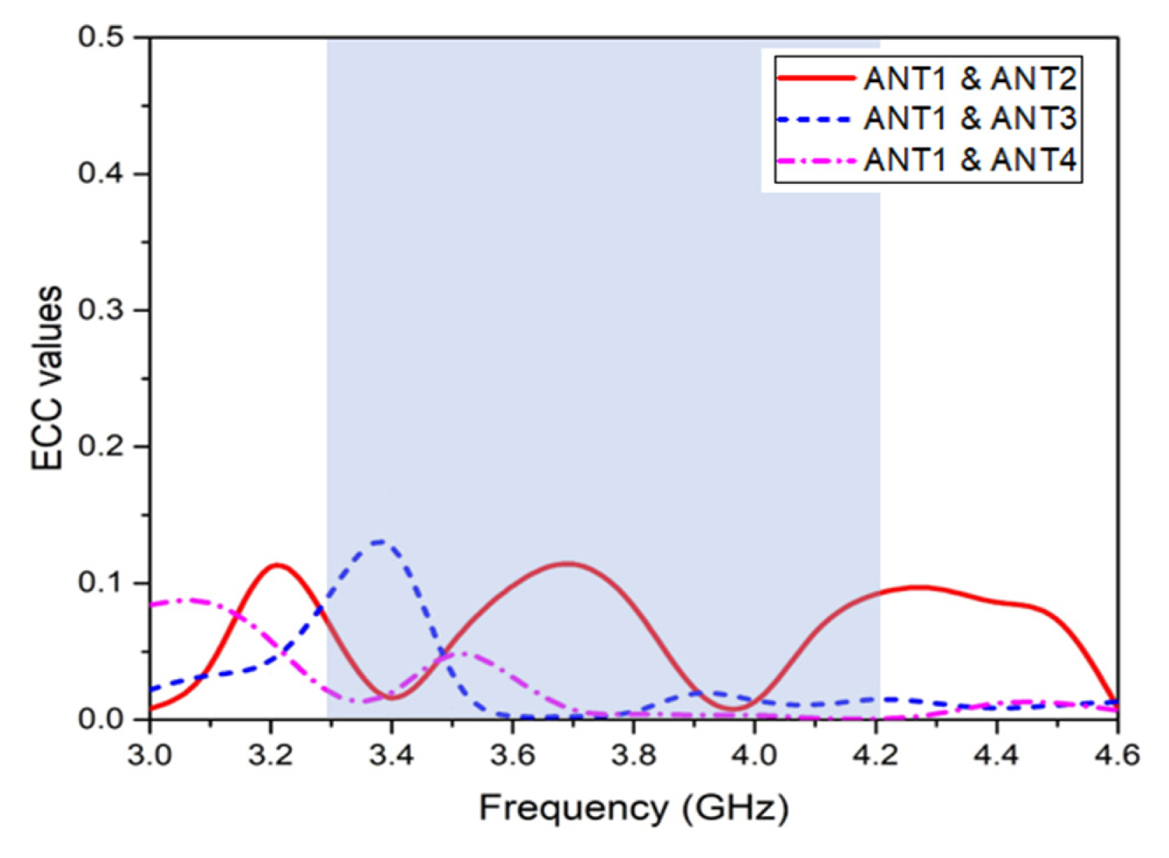
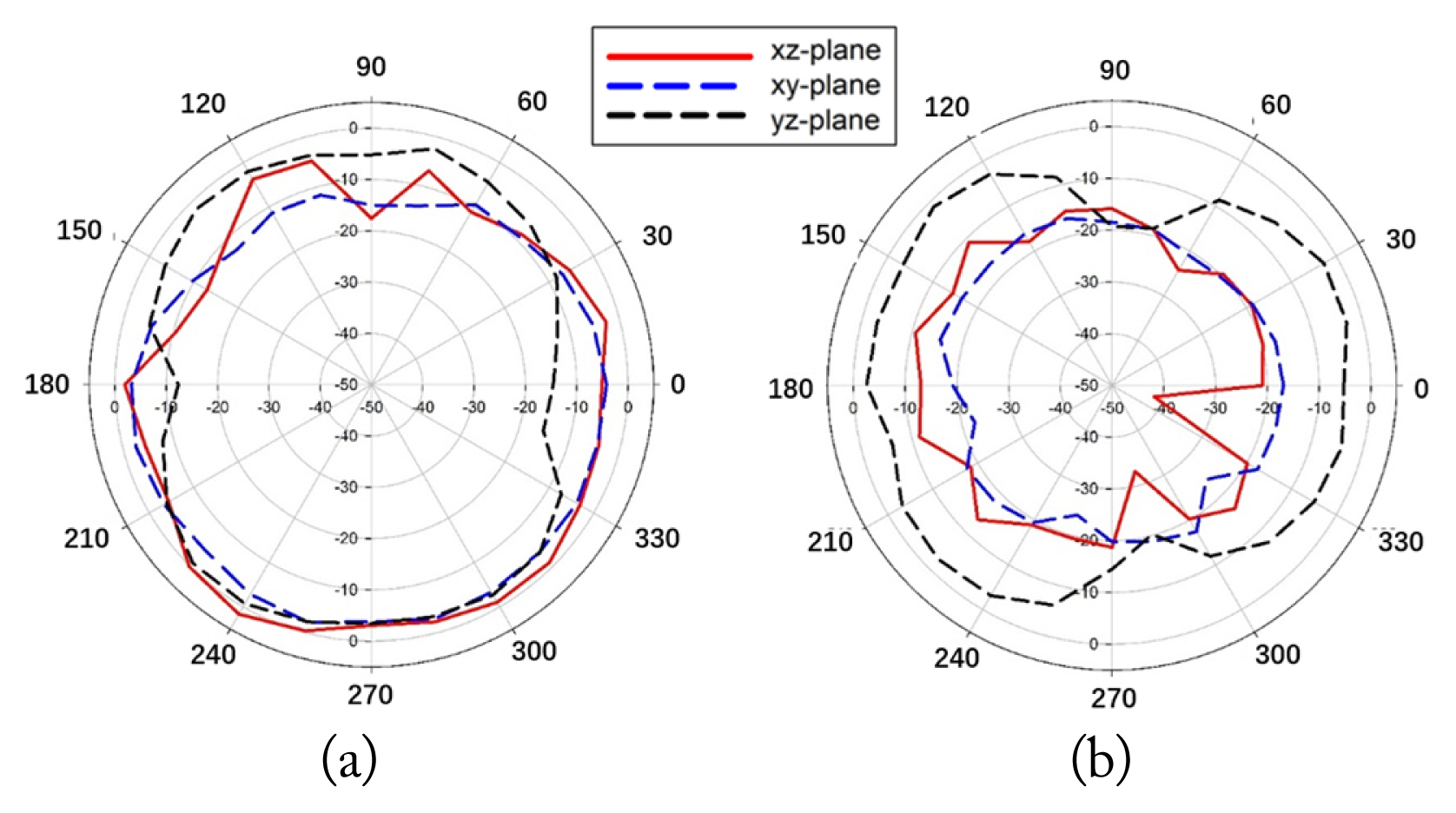
The 4 ├Ś 4 MIMO reference and proposed antennas were fabricated and measured using Agilent 8753ES network analyzers in a 6 m ├Ś 3 m ├Ś 3 m 3D CITA OTA chamber, as shown in Fig. 7. For input impedance matching, the feed structure series capacitor Ca and the resonance loop series capacitor Cg were set to 0.5 pF and 0.2 pF, respectively, for the reference antenna. Meanwhile, for the proposed antenna, the series capacitor Cg, the parallel capacitor Cs, and the resonance loop capacitor Cr were set to 0.4 pF, 0.25 pF, and 0.2 pF, respectively. The reflection coefficients presented in Fig. 8 show that a ŌłÆ6 dB bandwidth of 580 MHz (3.28 GHzŌĆō3.86 GHz) and 1,380 MHz (3.12 GHzŌĆō4.50 GHz) are obtained for the reference antenna and the proposed antenna, respectively. Furthermore, Fig. 9 shows the measured total efficiency data on average, where the reference ANT1 is at 38.7% and the proposed ANT1 is at 49.1% within the 3 GHz to 4.6 GHz range. The measurement results of mutual coupling between ANT1 and ANT4 of the proposed antenna are both lower than ŌłÆ15 dB, indicating characteristics that are similar to the simulation results, as shown in Fig. 10. Furthermore, the measured envelope correlation coefficient (ECC), derived from far-field 3D radiation patterns, is shown in Fig. 11. It is observed that all measured ECC values are below 0.2 in the target frequency band of 3.3 GHz to 4.2 GHz, which is significantly lower than the acceptable threshold of 0.5. This highlights that the proposed 4 ├Ś 4 MIMO antenna offers good diversity performance in the operating frequency band. Fig. 12 illustrates the radiation patterns of the proposed antenna at 3.5 GHz, with the far-field theta and phi directions showing good omnidirectional performance. These measurement results highlight that the proposed technology exhibits a wider bandwidth and better performance than the reference antenna.
V. FURTHER STUDY AND DISCUSSION
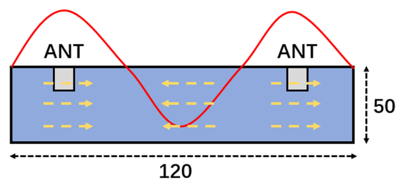
Previous studies have shown that if an antenna is located at the maximum current position on the ground plane, it exhibits good performance [12]. In general, in a MIMO antenna design, an isolator is used to reduce the isolation of the antenna and, in turn, to decrease interference to improve antenna performance [26]. The operation mechanism of the proposed MIMO antenna at 3.75 GHz is shown in Fig. 13. The length of the proposed antennaŌĆÖs PCB is 120 mm (about 1.5╬╗), with the antenna set located in positions with maximum current distribution [12]. The results show that all the proposed antenna sets exhibit good antenna performance.
In this context, since two sides of 5G mobile terminal equipment are primarily used in low-frequency antenna design (0.69ŌĆō0.96 GHz and 1.69ŌĆō2.69 GHz), adding more antennas to one side of the device has become increasingly challenging. Furthermore, with the increasing demand for data transmission on mobile devices, integrating more antennas into these devices has emerged as a trend [23]. Moreover, previous studies did not use the ground-radiation antenna for exploring the design of an n ├Ś n MIMO antenna. In this case, since no additional structure is used to reduce isolation in this study, one could add a set of antennas to the proposed antenna to construct a 6 ├Ś 6 MIMO antenna using the current distribution.
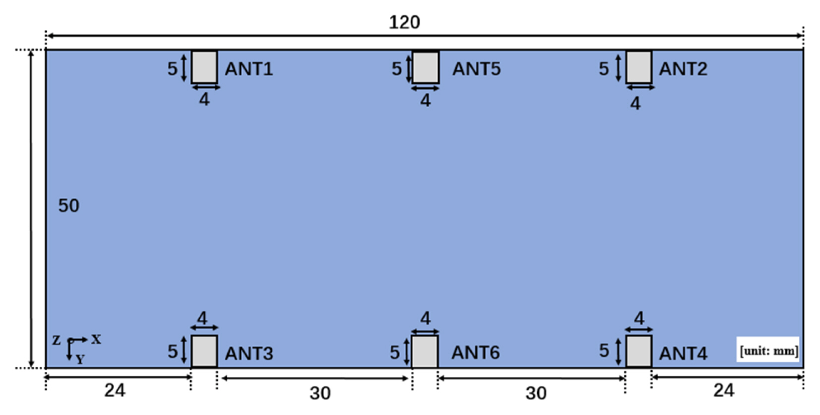
The design of the proposed 6 ├Ś 6 MIMO antenna system is shown in Fig. 14. Notably, the design for ANT1 to ANT4 in this antenna is the same as the 4 ├Ś 4 MIMO antenna set. Moreover, the ANT5 and ANT6 structures are the same as those of ANT1 and ANT3, thus maintaining mirror symmetry.
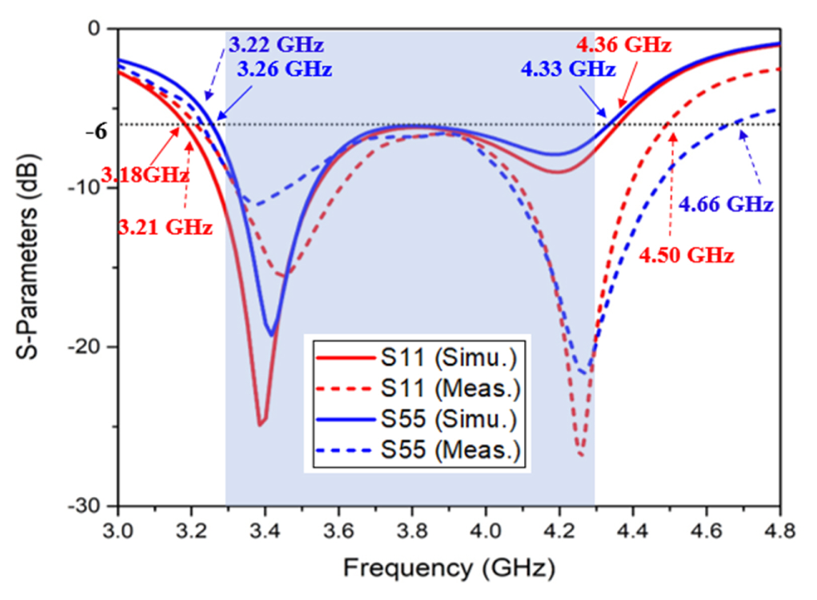
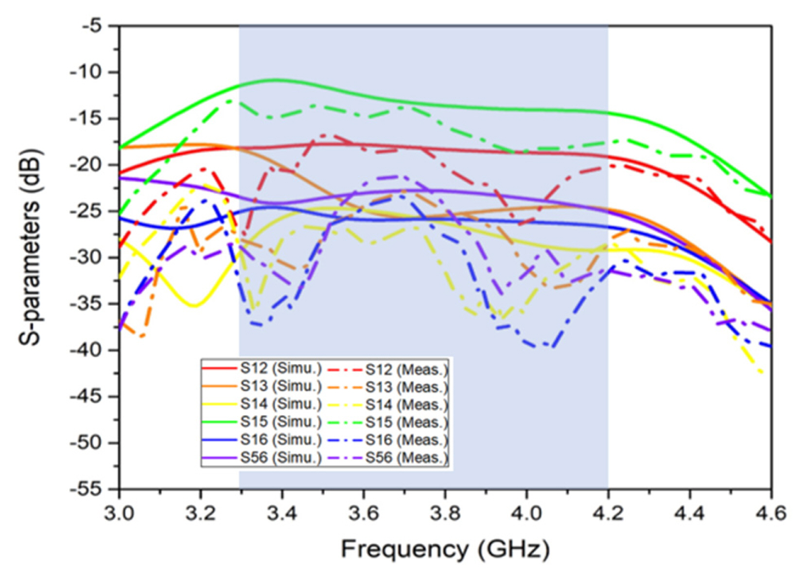
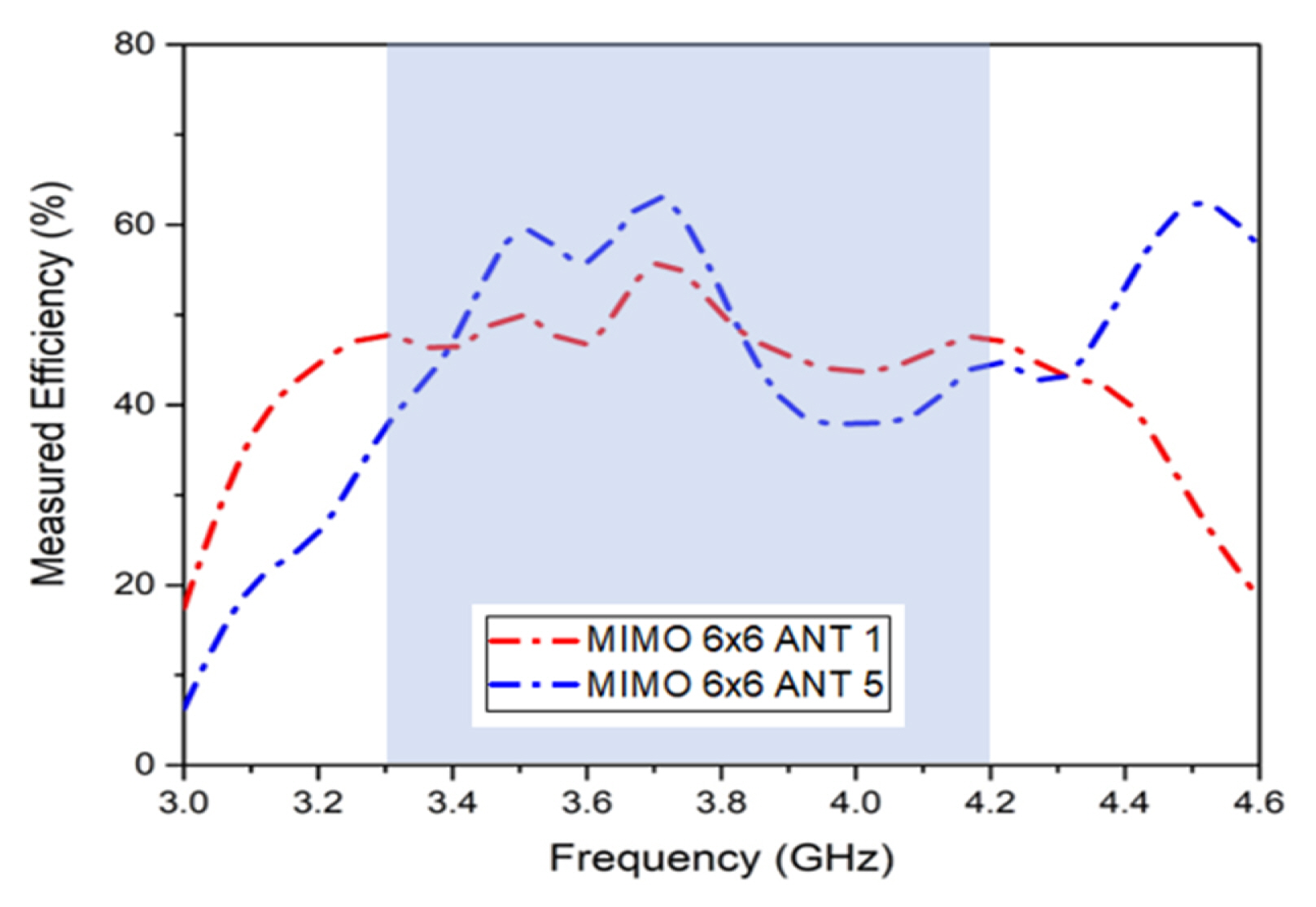
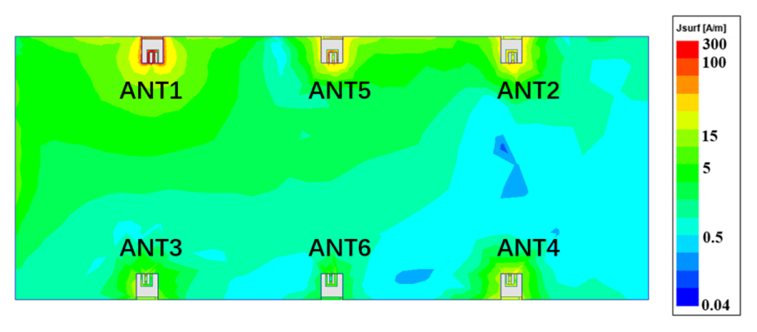
The S-parameters of the proposed 6 ├Ś 6 MIMO antenna are presented in Fig. 15, showing that the proposed S11 and S55 achieve a bandwidth of 1,180 MHz (ranging from 3.18 GHz to 4.36 GHz) and 1,070 MHz (ranging from 3.26 GHz to 4.33 GHz), respectively, under the ŌłÆ6 dB bandwidth, thus covering the target frequency band (3.3 GHz to 4.2 GHz). Both the simulation and measurement results for the proposed structure point to an S11 of 12,900 MHz (ranging from 3.21 GHz to 4.50 GHz) and an S55 of 1440 MHz (ranging from 3.22 GHz to 4.66 GHz) under the ŌłÆ6 dB bandwidth, which also covers the target frequency band. Furthermore, the simulated results of the isolation performance between the two antenna elements of the MIMO antenna set is over 10.9 dB, demonstrating good isolation between the proposed antennas. Meanwhile, the measurement results show that the isolation between two antenna elements in the MIMO antenna set is over 13.1 dB for the proposed antennas, as shown in Fig. 16. Fig. 17 illustrates the measurement results of the total efficiency data on average for the 6 ├Ś 6 MIMO antenna, where ANT1 is at 42.0% and ANT5 at 44.1% in the 3 GHz to 4.6 GHz range. The simulated surface current distribution at 3.5 GHz in the proposed 6 ├Ś 6 MIMO antenna system with Port 1 excitation is shown in Fig. 18. Furthermore, the measurement ECC results derived from the far-field 3D radiation patterns are shown in Fig. 19, where it is observed that all measured ECC values are below 0.2 in the target frequency band from 3.3 GHz to 4.2 GHz.
The simulated and measurement results demonstrate that the MIMO antenna can be designed without using isolators. Even without isolators, the current distribution used to select the antenna area maintained good isolation between the antenna elements while also achieving satisfactory bandwidth and performance. Further experimentation revealed that more antennas could be integrated into this structure through current distribution in the mobile device without the need for any additional structure. This method can be used as a reference when designing an antenna for mobile devices in the future. Table 1 compares the results of the proposed antenna with those attained in previous studies in terms of antenna size, bandwidth, efficiency, operating frequency band, and antenna type [5, 11, 17, 21, 23]. The comparison clearly indicates that the proposed antenna has a wider bandwidth than other antennas of the same type in the same operating frequency band. In addition, in contrast to previous studies, the proposed antenna offers the advantage of easy manipulation of impedance matching.
VI. CONCLUSION
This paper introduces a 4 ├Ś 4 MIMO antenna application based on the concept of the characteristic mode for 5G terminals. The proposed antenna uses a series and parallel capacitor feed structure to control input impedance matching while also employing ground radiation to achieve a ŌłÆ6 dB bandwidth of approximately 1,240 MHz (ranging from 3.14 GHz to 4.38 GHz) in the simulation and 1,380 MHz (ranging from 3.12 GHz to 4.50 GHz) in the measurement results. Furthermore, the experimental measurements of the proposed antenna demonstrated satisfactory efficiency, which increased from 38.7% (reference) to 49.1% (proposed), indicating good antenna performance. Moreover, the 6 ├Ś 6 MIMO antenna design using current distribution also exhibited satisfactory bandwidth and good antenna performance. Therefore, it is concluded that the proposed technology will have good application prospects for 5G communication terminals in the future.