Evaluation of Electromagnetic Exposure in Wireless Power Transfer Systems for Electric Vehicles
Article information

Abstract
In wireless power transfer (WPT) systems, the electromagnetic fields generated by a charging module may exceed the limits set by international safety guidelines. This is a matter of concern for the safety of users of high-power WPT systems, such as electric vehicles (EVs). To address this issue, this study designed a stationary WPT system for EV charging. Furthermore, the dosimetry of the system was evaluated for two exposure scenarios. Electromagnetic field data obtained using the electromagnetic field analysis tool were employed to derive the induced quantities in the human body using the impedance method. In addition, the obtained results were compared to the values recommended by international guidelines (International Commission on Non-Ionizing Radiation Protection).
I. INTRODUCTION
Wireless power transfer (WPT) systems deliver power across air gaps without requiring any physical connection, thus greatly improving the convenience and freedom of electronic device users. WPT has been applied to various fields and applications, with electric vehicles (EV) being the most promising high-power application of WPT technology. The strengthening of international environmental regulations has contributed to fossil fuel vehicles losing their market competitiveness to EVs, which are rapidly replacing them [1–4]. As the spread of EVs increases, suitable WPT technology that can be applied to these vehicles is also necessary [5]. In this context, stationary EV wireless charging has emerged as a method for supplying power to parked electric vehicles [5], where charging occurs automatically when an EV side receiver is located within the charging area of the transmitter. This method can be utilized in places equipped with charging infrastructure, such as charging stations or parking lots, in a way similar to the plug-in method. Furthermore, with the recent development of unmanned self-driving vehicles, it is evident that more electronic devices are being operated in electric vehicles, as a result of which power consumption inside the vehicle is also increasing [6]. Therefore, EV wireless charging is an essential technology that must be realized to facilitate fully autonomous driving.
As the number of electric devices used inside vehicles increases, concerns about electromagnetic compatibility (EMC) and electromagnetic safety have been attracting substantial attention. Since high-power EV wireless charging systems emit a much stronger electromagnetic field (EMF) than other electronic devices, the effect of the high-energy EMF generated around a WPT EV charging system on other electronic devices and the human body cannot be ignored [7, 8]. In particular, high-energy EMFs cause malfunctions in implantable medical devices (IMDs), such as pacemakers and neurostimulators [9–12]. Therefore, to protect users and electronic devices from high-energy EMFs, many previous studies have focused on reducing the leakage of magnetic fields [13, 14]. Furthermore, international standards for quantifying the strength of exposure to electromagnetic fields and the amount of human body induction were discussed by the International Commission on Non-Ionizing Radiation Protection (ICNIRP) [15, 16]—a body responsible for prescribing guidelines for protecting the human body from EMFs. All EV wireless charging systems must be designed in compliance with ICNIRP’s standards and guidelines.
This study analyzes the effect of stationary WPT systems for EV charging on EMF and the human body at 85 kHz. Furthermore, a stationary WPT system model designed to meet international standards (SAE J2954 and IEC 61980) as much as possible has been proposed [17, 18]. The effect on the human body and EMF are evaluated by comparing the results obtained from analyzing two cases—with and without an EV structure—pertaining to a stationary WPT system model. Furthermore, to account for the worst possible circumstances, the human body model is assumed to be situated closest to the charging module, with the maximum current allowed by the charging system flowing through the transmitter and receiver. The novelty of this study lies in the fact that the evaluation of electromagnetic exposure was performed using a WPT EV charging system with a multi-coil structure, while the shielding performance of the EV body structure was evaluated in terms of the induced quantities of a human body model. To prevent human exposure to electrical stimulation effects below 10 MHz, the internal electric field (ICNIRP 2010) and current density (ICNIRP 1998) are evaluated based on the ICNIRP guidelines, which have fixed a specific absorption rate (SAR) as a basic restriction for protection against thermal effects. However, since the thermal effect is dominant at frequencies of 100 kHz or higher, it was not considered in this study.
II. WPT PICKUP COIL MODEL
1. Stationary WPT Model for EV Charging
The designed stationary WPT system operates following a single-input single-output (SISO) method. To transmit power, the magnetic field radiating from the system’s transmitter side generates an induced current on the receiver side. The pickup coil was designed according to a structure and size suitable for charging EVs. Fig. 1 shows the configuration of the stationary WPT system for EV charging proposed in this paper. As depicted in Fig. 1(a), the transmitter coil contains a multi-coil structure in which square and rectangular coils are symmetrically arranged, while the receiver coil is composed of a large coil located at the center with small coils attached to both sides, as shown in Fig. 1(b).
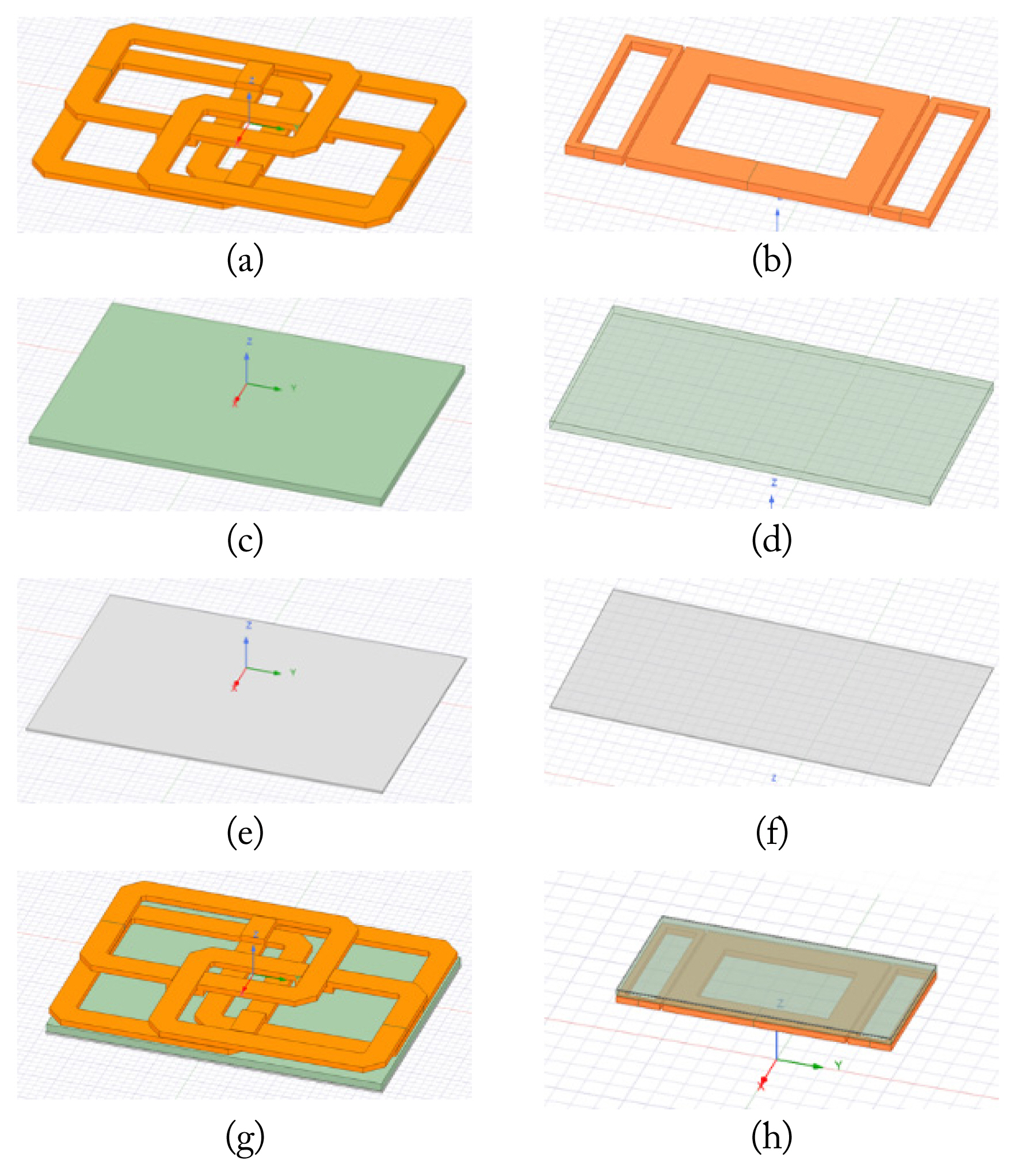
Configuration of the stationary WPT pickup coil model for EV charging: (a, b) coil structure, (c, d) ferrite plate, (e, f) aluminum plate, and (g, h) the combined WPT pickup coil model.
The transmitting and receiver coils are constructed on a 20-mm thick rectangular ferrite plate with a relative permeability of 3,200 (H/m), as shown in Fig. 1(c) and 1(d). The ferrite plate not only shields the leakage magnetic field but also offers advantages pertaining to WPT performance, such as improving the coupling coefficient and quality factor of the coil [19]. Notably, ferrite materials are used in most WPT modules due to their high magnetic permeability and low eddy current loss and hysteresis loss. The aluminum conductor plates in Fig. 1(e) and 1(f) are placed outside the coil and the ferrite plate for the purpose of shielding the EMF and minimizing electromagnetic interference (EMI). In a high-power WPT system, high-intensity EMFs may be generated during the power transmission process. Therefore, a shielding plate is required to prevent the spread of a high-intensity magnetic field outside the charging area. Fig. 1(g) and 1(h) present the completed transmitter and receiver pads with all the parts combined. The dimensions of the transmitting and receiving pad structures are 850 × 630 × 57 mm3 and 600 × 300 × 28 mm3, respectively. Furthermore, to compensate for the decrease in power transfer efficiency due to misalignment between the transmitting and receiver coils, the latter’s size was designed to be smaller than the former. The inductances of the transmitter coil and receiver coil were measured as 64 μH and 126 μH, respectively.
Fig. 2 depicts the typical neutral position of the transmitter and receiver coils when the system is in operation. When the centers of the transmitter and receiver coils are the same, the system achieves correct alignment. This is defined as the neutral position, as shown in Fig. 2(a). Notably, the transmitter coil is located above the ground, while the receiver coil is located under the lower steel plate of the EV. Furthermore, as illustrated in Fig. 2(b), the air gap between the transmitter coil and the receiver coil was set to 170 mm. For the system operating frequency, a value of 85 kHz was chosen since it is commonly used for EV wireless charging modules. The maximum output current and power of the WPT system transmitter were designed to be 100 Arms and 35.7 kW, respectively, while the maximum output current and power of the receiver was 75 Arms and 22 kW, respectively.

Neutral position of the stationary WPT pickup coils: (a) top view and (b) front view.
III. GUIDELINES AND NUMERICAL METHOD
1. ICNIRP Guidelines
The ICNIRP provides reference guidelines for the protection of humans and the environment from electromagnetic radiation exposure. Furthermore, as shown in Table 1, the ICNIRP also establishes the acceptable limits for the electric field (V/m), magnetic field (A/m), current density (published by ICNIRP 1998), and the 99th percentile electric field (revised by the ICNIRP in 2010). These guidelines are aimed at protecting the human body from the electrical stimulation effect that occurs on exceeding the standard value in the low frequency band of 100 kHz or less. The latest ICNIRP guidelines are its 2020 version, which revised the specifications for the RF band (100 kHz–300 GHz). However, since its previous version is still being used for the low frequency (LF) band (1 Hz–100 kHz), this study accounts for both the 1998 and 2010 versions released by the ICNIRP.
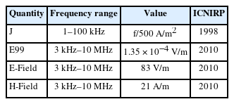
Relevant ICNIRP exposure limits for the operating frequency
Notably, the guidelines mandated by the ICNIRP are usually more stringent than those established by the IEEE safety standards. Since these guidelines are widely used as indicators for evaluating safety in most countries, they are well suited for evaluating the effects of EMFs on the human body. In this context, it should be noted that the 99th percentile electric field (E99) represents the 99th percentile value of the electric field vector inside the volume of magnitude. According to the guidelines, the electrical stimulation effect is more dominant than the thermal effect below 100 kHz. Therefore, the SAR guidelines are not considered in this study, since the frequency of the proposed system is 85 kHz. Under an operating frequency of 85 kHz, the current density limit mandated by the ICNIRP in 1998 is 170 A/m2, while that for the electric field, as determined in 2010, is 11.475 V/m, based on basic restrictions.
2. Numerical Method and the Human Body Model
Usually, experimentally measuring the current density and electric field induced inside a living human body by EMF exposure is considered an extremely difficult task. Although nonhuman mammals, such as mice, have sometimes been experimented upon to attain actual measurement results [20], these estimates do not comprehensively represent the relevant information pertaining to the real human body. Therefore, a numerical method is necessary to obtain the induced quantities inside the human body. To achieve this, the EMF around the WPT system must first be calculated. Considering the magnetic field of the area where the human body model is located as the incident magnetic field, the induced quantities can be calculated by applying the body tissue medium to each voxel. In general, to calculate the induced quantities of a specific object, it is necessary to include the object in the WPT system configuration model and then analyze it. However, since the human body is composed of a medium characterized by low reflection characteristics for EMFs, the electromagnetic interaction between a wireless charging system and the human body is sufficient to be ignored [21].
Therefore, this study calculated the induced quantities in the human body based on the incident magnetic field around the system. EMF analysis was performed around the wireless charging module using Ansys MAXWELL. The adult male body model TARO (640 × 320 × 1,732 mm3) was employed to calculate the induced quantities. The impedance for each voxel was calculated using the following equation:
where σ and εr refer to the conductivity and relative permittivity of human tissue, ε0 indicates the vacuum permittivity, while l and S are the edge length and cross-sectional area of the voxel. Since the electrical characteristics of each part of the human body are not uniform, a three-dimensional (3D) impedance network was modeled by calculating the x, y, and z-direction impedances for each voxel boundary, also known as the impedance method [22]. The σ and εr parameters of the body tissue of the TARO model for each voxel at 85 kHz were measured by Gabriel [23]. Furthermore, the closed-loop voltage of the cross-sectional area induced by the magnetic field was obtained using Faraday’s law, as follows:
where ds refers to the unit of area within the loop and μ0 represents the magnetic permeability of the vacuum. Using Eqs. (1) and (2), the 3D human body impedance network and the closed-loop voltage at each voxel were identified, and all the loop currents in the human body impedance network were obtained. Subsequently, the internal electric field induced inside the human body was calculated using the following equation:
Since the spatial resolution of each voxel is considered 2 mm in this research, the analysis space of the TARO model should be 640 × 320 × 1,732 (x × y × z). Furthermore, the current density (J) and the 99th percentile electric field (E99) induced in the human body were calculated using Eq. (3).
IV. FIELD EVALUATION AND DOSIMETRY FOR WPT
1. Exposure Scenarios
Fig. 3(b) presents the configuration including the EV structure (Case 2). In Case 2, the simulation was performed at a distance of d1 = 10 mm between the EV structure and the human body model, thus assuming a scenario where the human body is most vulnerable to EMF exposure in the stationary WPT system that includes the operating EV structure. The human body model is located at d2 = 920 mm from the transmitter. A tendency to use lightweight materials (alloys, ceramics, and reinforced plastics) for the body of EVs has recently emerged. However, since these materials are used only in parts of the overall structure and are not yet popular, iron is chosen as the material for the EV structure. To compare the shielding effect of the EV structure with an iron body, an analysis without the EV structure case was also performed (Case 1), as shown in Fig. 3(a). The position of the human body model in Case 1 maintained the same distance of d2 = 920 mm from the transmitter as in Case 2. The d2 is defined based on the full width of the EV body structure. Notably, in this study, d2 was calculated based on the full width of the most common EV, which is 1,840 mm.

Location of the TARO human body model: (a) without the EV structure (Case 1) and (b) with the EV structure (Case 2).
2. Field Strength Evaluation
To simulate the worst possible scenario, the sinusoidal root mean square (RMS) currents flowing through the transmitter and receiver coils were set to their maximum values of 100 Arms and 75 Arms, respectively. Considering the optimum matching conditions between the transmitter and the receiver, the simulation was performed by considering the current in the receive coil lagged by 90° than in the transmit coil. Fig. 4 illustrates the magnetic field strength in dB(H) for Cases 1 and 2 in the stationary WPT system. Since the WPT system uses the magnetic induction method, the magnetic field strength is highlighted rather than the electric field strength. The ICNIRP reference level (21 A/m) is marked by a solid black line. Unlike the electric field exceeding the established limit detected outside the EV width area in the YZ plane, no such activity is detected outside the EV length area. Therefore, an exposure evaluation for the XZ plane was not performed.

Magnetic field strength in dB(H) in the stationary WPT system: (a) Case 1 and (b) Case 2.
As evident in Fig. 4(a), the extent to which the Case 1 magnetic field boundary exceeds the reference level is 845 mm in the ±y direction, 820 mm in the +z direction, and 570 mm in the −z direction from the center of the transmitter coil. Since the transmitter coil current is higher than the receiver coil current, and its coil size is also larger, most of the magnetic field around the receiver coil exceeds the reference level, even though the receiver coil has a shielding plate. Meanwhile, some areas do not exceed the reference level due to the shielding plate located at the lower part of the transmitter coil. Overall, a magnetic field exceeding the reference level is observed in all directions around the module. This indicates that the magnetic field shielding works as expected only in a few parts behind the ferrite and aluminum plates as the shielding plate.
This study also performed another simulation, where an additional EV structure was placed behind the receiver pad, as shown in Fig. 4(b). The EV structure is implemented with dimensions of 4,300 × 1,840 × 1,450 mm3, which characterizes the bulk of typical electric vehicles, consisting of a 2-mm thick six iron plate. The extent of the Case 2 magnetic field boundary exceeding the reference level is 950 mm in the ±y direction and 650 mm in the −z direction from the center of the transmitter coil. Although expansion beyond the reference level boundary is observed in the ±y direction due to the EV structure, it does not extend substantially beyond the width of the EV structure. Since the iron plate EV structure works as a shield, similar to the aluminum and ferrite plates, the magnetic field is completely shielded. As a result, the field exceeding the reference level is not detected inside the vehicle (+z direction). However, the strength of the magnetic field reflected from the shield is concentrated at the lower side of the module, leading to the reference level boundary expanding in the −z direction.
3. Dosimetry using the Human Body Model
By applying the impedance method to the magnetic field data obtained from the Ansys MAXWELL simulation, the values for the current density (J) and electric field of the 99th percentile value (E99) were calculated and evaluated. The induced J was averaged over a 1 cm2 cross-section perpendicular to the current direction (A/m2), as noted in the ICNIRP guidelines published in 1998. Meanwhile, E99 refers to the 99th percentile value of the internal electric field vector in a 2 × 2 × 2 mm3 size cube (V/m), as noted in the ICNIRP guidelines published in 2010.
Fig. 5(a) and 5(b) depict the magnitude of current density induced in the adult male human body model TARO in Cases 1 and 2, respectively. The magnitude of current density lies within the range of −80 dB to −10 dB. Notably, the current density induced in the human body is smaller for Case 2, which included the EV structure, than for Case 1, which did not include the EV structure. Since both figures appear to be very similar, it might not be easy to observe differences between them. However, a clear distinction can be recognized between Cases 1 and 2 when comparing the current densities near the lungs and the bladder of the TARO model. This was observed when comparing the current densities induced in the lower body parts (thigh and waist parts). Despite the magnetic field exceeding the reference level by 130 mm in Case 2 than in Case 1, the reason that the induced human body current density in Case 2 is lower than in Case 1 is because it is completely shielded in the +z direction in the former scenario, unlike in Case 1, where a magnetic field was produced in all directions around the module. Therefore, the total amount of magnetic field incident on the entire body is lower in Case 2 than in Case 1, except for the body parts located relatively close to the module.
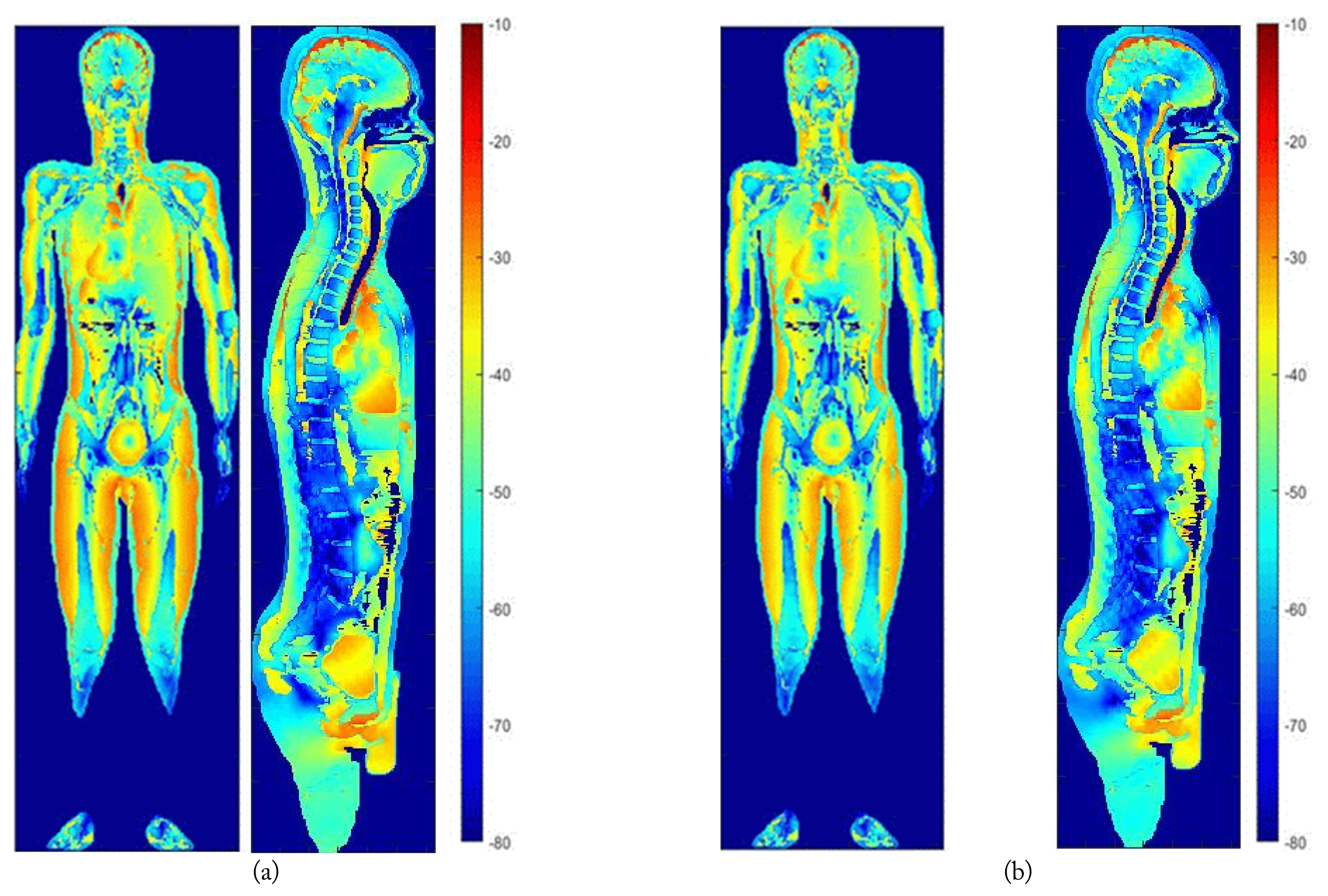
Cross-sectional current density distributions: (a) Case 1 and (b) Case 2.
Table 2 lists the maximum values of L and E99 for both cases, with Jcns and E99cns representing the J and E99 for the central nervous system tissue, respectively. In Case 1, the J and Jcns are 1.419e-1 and 2.344e-2, respectively, which are larger values than those obtained for Case 2—1.051e-1 and 1.825e-2, respectively. This validates the analysis results of the current density distributions presented in Fig. 5(a) and 5(b). In Case 1, the E99 and E99cns are 2.69e-1 and 1.203e-1, respectively, which are again larger than the values obtained for Case 2—2.254e-1 and 9.958e-2, respectively. Since the maximum current density limit prescribed by the ICNIRP is 170 A/m2 and the electric field limit is 11.475 V/m, both Cases 1 and 2, in which the human body model was separated by d2 = 920 mm from the wireless charging module, did not exceed the limit set by the ICNIRP. However, in the absence of an EV structure, the human body model may be situated closer to the pickup coils than d2 = 920 mm, in which case the EMF exposure intensity would increase. Therefore, future research should conduct further evaluations of electromagnetic exposure by accounting for various scenarios beyond those presented in Cases 1 and 2.

Induced quantities in the human body
V. CONCLUSION
In this study, EMF simulation and human body model analysis were performed for an 85 kHz stationary WPT charging module. Using the EMF analysis tool, the magnetic field distribution data generated by a stationary EV WPT system were obtained, following which the induced quantities in the human body were derived using the impedance method. Two exposure scenarios were considered for evaluation (with an EV structure and without an EV structure). The dosimetry results in each case were compared to the established international guidelines, and the resulting observations were discussed. The results obtained in this study provide references and examples of stationary EV WPT charging systems that can be beneficial for EMF safety design.
ACKNOWLEDGMENTS
This work was supported by the Korea Institute of Energy Technology Evaluation and Planning (KETEP) grant funded by the Korean government (MOTIE) (No. 202020–20800060).
References
Biography

Kyeung-Won Bang, https://orcid.org/0000-0001-9817-9990 received his B.S. and M.S. degrees in electronics and control and instrumentation from Daegu University, Daegu, South Korea, in 2019 and 2021, respectively. Since 2023, he has been working as a researcher at the soonchunhyang university. His current research interests include power electronics, EMC/EMI analysis, wave propagation, and wireless power transfer. In his future research, he intends to explore the application of deep learning to solve nonlinear characteristics in PCB circuits.

Sang-Wook Park, https://orcid.org/0000-0001-6996-5853 received his B.S. and M.E. degrees in radio science and engineering from Chungnam National University, Daejeon, South Korea, in 2003 and 2005, respectively, and his Ph.D. degree from the University of Electro-Communications (UEC), Tokyo, Japan, in 2008. In 2008, he joined UEC as an assistant professor in the Department of Information and Communication Engineering. From 2009 to 2013, he was a researcher at the National Institute of Information and Communications Technology in Tokyo. From 2013 to 2018, he worked as a senior researcher at the Korea Automotive Technology Institute, Cheonan, South Korea. From 2019 to 2022, he was an assistant professor in the Division of Electronic and Electrical Engineering, College of Information and Communication Engineering, Daegu University, Gyeongsan, South Korea. Since 2023, he has been an assistant professor in the Division of Electronic Engineering, College of Engineering, School of Engineering, Soonchunhyang University, Asan, South Korea. His current research interests include wireless power transfer, electromagnetic interference/electromagnetic compatibility (EMC), microwave transmission circuits, numerical analysis, biomedical EMC, electromagnetic wave propagation, and automotive information and communications technology convergence.

Hong-Guk Bae, https://orcid.org/0000-0002-0040-6831 received his B.S degree in electronic engineering from Daegu University, Daegu, South Korea, in 2022. Since 2023, he has been working as a researcher with Prof. Sang-Wook Park. His current research interests include wireless power transfer, electromagnetic interference/electromagnetic compatibility (EMC), microwave transmission circuits, numerical analysis, biomedical EMC, electromagnetic wave propagation, and automotive information and communications technology convergence.

Byeong-Yoon Lee, https://orcid.org/0009-0000-7862-7565 received his B.S., M.S., and Ph.D. degrees in electrical engineering from Seoul National University in 1990, 1992, and 1997, respectively. Since 1996, he has been a senior research engineer at the Korea Electrotechnology Research Institute. His research interests are electromagnetic field analysis, evaluation of human exposure to electromagnetic fields, wireless power transfer technology for electric vehicles, and digital twin technology for smart grids.

Hui-Myoung Oh, https://orcid.org/0009-0003-5521-2959 received his B.S. degree in electrical engineering from Yonsei University, Seoul, Korea, in 1998, and his M.S. and Ph.D. degrees in electrical and electronic engineering from the same university in 2000 and 2009, respectively. He was a researcher at the Korea Electrotechnology Research Institute from 2001 to 2005 and a senior researcher from 2006 to 2015. Since 2016, he has been working as a principal researcher at the same institute. His research interests include digital communication systems, digital twin systems, EV communication protocols, and smart grids based on renewable energy.

Chang-Un Park, https://orcid.org/0009-0005-2679-3058 received his B.S. and M.E. degrees in electronics and information engineering from Korea University, Sejong, South Korea, in 2008 and 2010, respectively. Since 2010, he has been a senior researcher at the Power ICT Research Center, Korea Electrotechnology Research Institute, Ansan, South Korea. His current research interests include electric vehicle charging systems, smart grid IoTs, tactical information, power line communication, and wireless sensor networks.

Seung-Hyuk Baek, https://orcid.org/0009-0002-5410-9733 was born in South Korea in 1992. He received his M.S. degree in electronics engineering from Hanyang University ERICA, Ansan, South Korea, in 2022. He is currently working as a research associate in the Power ICT Research Center at Korea Electrotechnology Research Institute, Ansan, South Korea.