I. Introduction
Beam steering array antennas are used in a variety of applications, such as radar and wireless communication, etc., because of their novel agile beam control capability [1, 2]. Numerous research efforts have reported beam steering methods and antenna structures to control radiation patterns and polarization [3ŌĆō7]. However, conventional active phased array antennas are widely adopted for beam steering antenna applications, but they require complex feeding networks, high-power consumption, and high-cost transceiver (TRx) systems [8, 9]. Recently, transmitarray and reflectarray antennas have become the focus of significant research owing to their low cost, low power consumption, and low system complexity compared to the conventional active phased array. For this reason, studies related to transmitarrays and reflectarrays have been reported [10ŌĆō13]. There are two main types of transmitarray antenna design. One type is a transmitarray composed of receive (Rx) and transmit (Tx) antennas, along with a phase shifter. Reconfigurable RF circuits, such as phase shifters and RF switches, achieve beam steering and polarization conversion [14ŌĆō17]. The other type is a transmitarray using a frequency selective surface (FSS) [18, 19]. In this case, multi-layer FSS using PIN diodes [20] and varactors [21] are adopted because it is challenging for a single-layer FSS to achieve a relative phase shift of 360┬░. Compared with the multilayer FSS-based transmitarray the RF circuit-based transmitarray type features a relatively low profile and a greater degree-of-freedom for beam forming and polarization conversion.
Similar to metasurface and FSS structures, a transmitarray is composed of an array of unit cells that can manipulate the phase or polarization of incident waves. The overall performance of a multifunctional transmitarray is heavily dependent on the individual unit cell performance. Therefore, unit cell verification plays a crucial role in debugging errors and inferring overall transmitarray or metasurface performance. By employing a rigorous unit cell verification method, the design effort and time required for a large transmitarray or metasurface design can be significantly reduced. Thus, unit cell functionality verification is one of the most critical design steps for mitigating potential risks when designing a full multifunctional transmitarray.
Recent studies have reported unit cell verification using the transition of two waveguides, confirming the characteristics of the unit cell with S-parameters inside the waveguide [22, 23]. However, this verification has some limitations because it verifies the unit cell inside the closed space of the waveguide. In the case of polarization conversion verification, it is necessary to convert the dominant mode of the waveguide according to the polarization conversion. However, it is difficult to reliably convert the dominant modes in conventional rectangular waveguide structures. Since the unit cell is verified using the S-parameter, the unit cell is limited to confirming the far-field and real-time beam steering characteristics of the transmitarray antenna. For this reason, there is a need for novel methods that verify unit cells in transmitarrays and surpass the limitations of previous approaches.
The present study proposes a unit cell verification method using a simple TE10 mode rectangular waveguide feeding network. The unit cell performance, such as beam steering and polarization selection, was verified and analyzed using the proposed unit cell verification method. Further, based on the unit cell verification, the performance of the reported 8 ├Ś 8 transmitarray antenna was compared [24]. The remainder of the paper is organized as follows. In Section II, the components and measurements of the unit cells are presented and discussed. The unit cell verification method and its operation principle are described in Section III. Section IV presents the conclusions drawn from the findings.
II. Unit Cell Structure
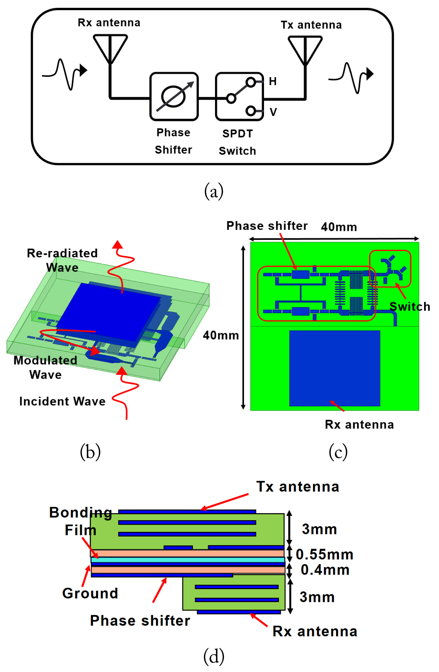
Fig. 1 shows the unit cell of the proposed transmitarray antenna for polarization conversions and beam steering operations in the S-band. The unit cell consists of three parts: the Rx antenna, Tx antenna, and control circuits, including a phase shifter and an SPDT PIN diode switch. The Rx antenna and circuit components were placed in the same plane, and the Tx antenna was placed on the opposite side. The incident wave was received by the Rx antenna, and the phase and polarization of the Rx wave were modulated by the RF circuit parts. The modulated wave was re-radiated by the Tx antenna. To avoid grating lobe and scan blinds, the size of the unit cell was limited to 0.4╬╗0 ├Ś 0.4╬╗0, which is a smaller unit cell period than the period of conventional transmitarray designs (0.5╬╗0 ├Ś 0.5╬╗0) [8]. The proposed unit cell architecture featured a planar low-profile structure and was fabricated using conventional low-cost, well-developed FR4 PCB technology (╔ør = 4.4, tan ╬┤ = 0.023). As shown in Fig. 1(d), the circuit layer and the Tx antenna feeding layer were attached using a bonding film, and the antennas (Rx and Tx) were fixed to this attachment layer with nylon bolts and nuts.
1. Antenna Design: Rx and Tx Antennas
The Rx and Tx antennas were mounted at the bottom and top of the unit cell. The antenna performance of a transmitarray unit cell is critical because these antennas directly receive and reradiate the signal from a source antenna. Therefore, the antenna should have a high gain and a proper radiation pattern. In this work, both Rx and Tx antennas were designed as stacked patches, considering the limited size of the unit cell (0.4╬╗0 ├Ś 0.4╬╗0). Fig. 2 shows the geometries of the proposed Rx and Tx antennas. The antennas had improved bandwidth due to a three-layer of stacked patches and proximity coupled feeding [25, 26]. When an antenna is designed on a high-loss substrate, its radiation efficiency declines due to interactions with the loss of substrate. This reduction directly affects the overall performance of transmitarrays. To address this issue, the implementation of a three-layer patch results in a more centralized electric field for the antenna compared to a conventional patch antenna, thus improving antenna directivity. It reduces the interaction between the field and the high-loss FR4. As a result, the loss of the antenna is minimized, leading to an increase in gain.
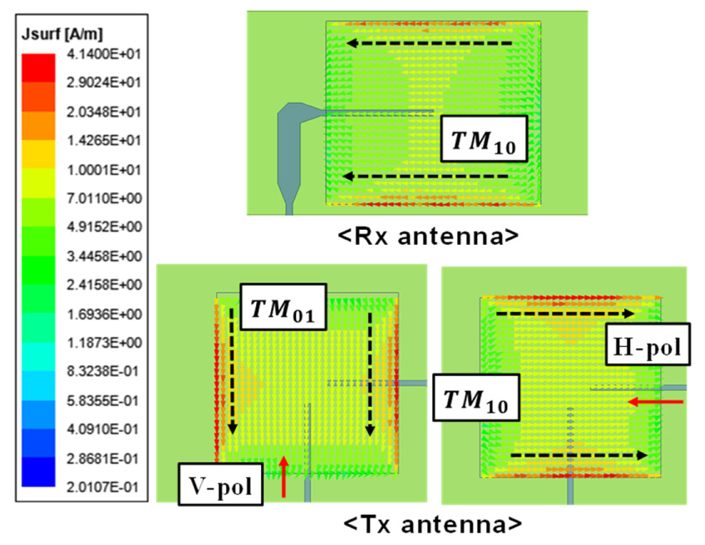
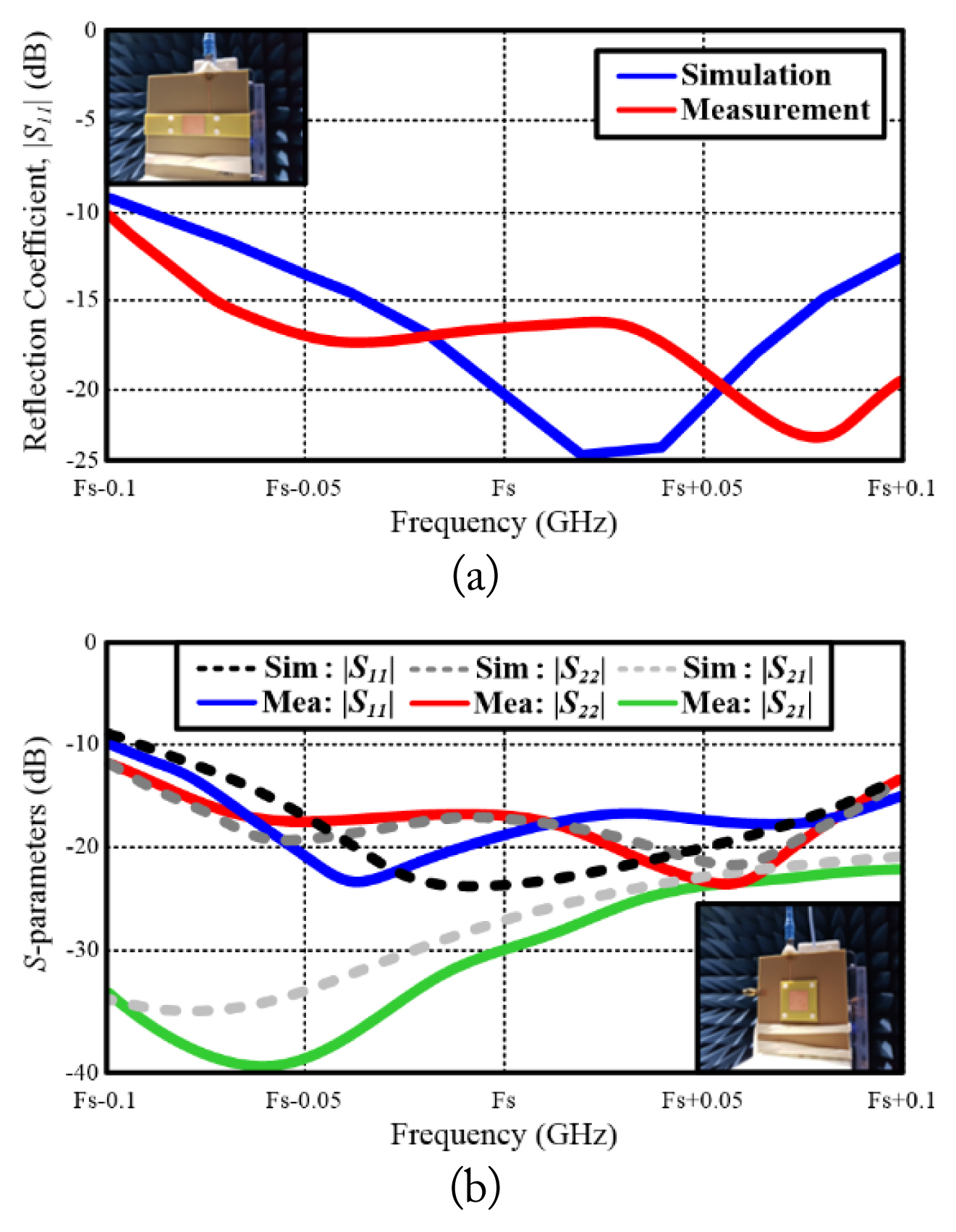
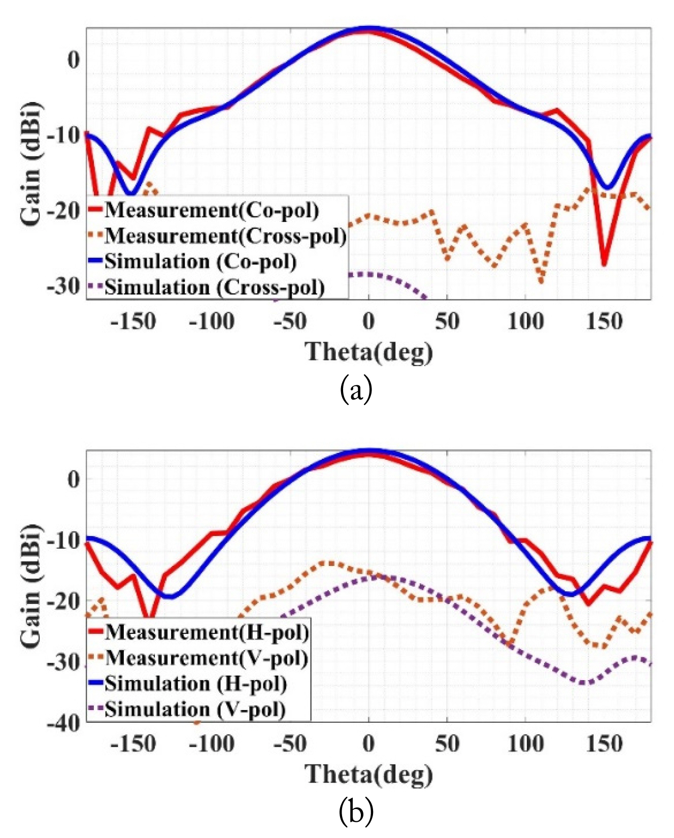
The current distribution of the Tx and Rx antennas is illustrated in Fig. 3. Although the Rx and Tx antennas have similar stacked patch structures, there is a significant difference in antenna polarization. The Rx antenna is designed for single linear polarization, whereas the Tx antenna supports dual-linear polarization for polarization selection. As a result of this difference, the Tx antenna features two orthogonal distributions, while the Rx antenna has a single distribution. These surface current distributions provide insights into the resonance mode of Tx (TM10, TM01) and Rx (TM10) antenna. Fig. 4 shows the S-parameters and the fabricated Rx and Tx antennas. Each antenna was measured in an anechoic chamber, as shown in the inset of Fig. 4. The ŌłÆ10 dB impedance bandwidth of each antenna was sufficiently broad to cover the design target of Fs ┬▒ 0.05 GHz. The measured port isolation level between H-pol and V-pol was higher than 20 dB. Both the Rx and Tx antennas had broadside radiation patterns, as shown in Fig. 5. The co-pol and cross-pol gain values of the Rx antenna were measured to be 3.8 dBi and ŌłÆ21 dBi, respectively, at the operation frequency. The measured co-pol and cross-pol gain values of the Tx antenna were 4.25 dBi and ŌłÆ18 dBi, respectively, at the operation frequency. Certain discrepancies were observed between the simulation and measurements, as depicted in Figs. 4 and 5. During the fabrication process of the Rx and Tx antennas, three radiation layers were interconnected using bolts and nuts, which was challenging to precisely assemble by hand. As a result, small gaps occur between the layers, leading to subtle differences. However, despite these discrepancies, the simulations and measurements exhibited good agreement. Consequently, based on the aforementioned results, we confirmed that the antennas worked well as a Tx/Rx antenna.
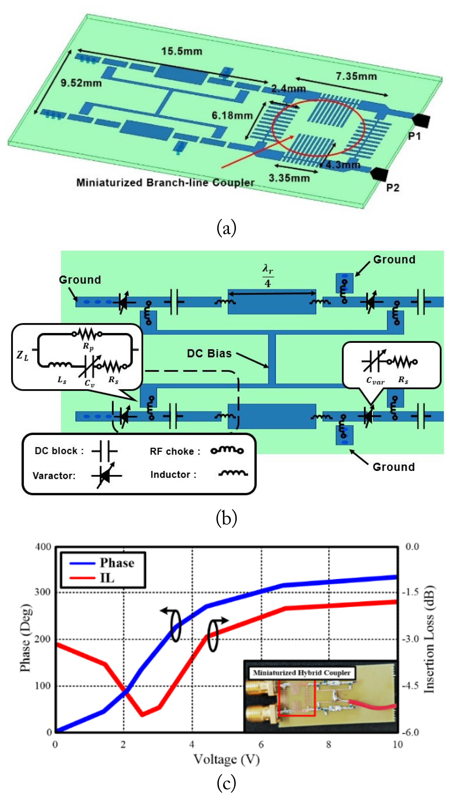
2. Control Circuit for Phase and Polarization
At the bottom of the unit cell, as depicted in Fig. 1(c), there was an Rx antenna along with the control circuit. The control circuit comprised two main components: the phase shifter and the SPDT switch. Given the smaller size of the unit cell, careful consideration is required for the design of the phase shifter. To address this, this paper presents a miniaturized reflection-type phase shifter, as illustrated in Fig. 6(a). The proposed phase shifter consists of inductively loaded transmission lines for system miniaturization and two reflection loads for a broad phase-shift range of 0┬░ŌĆō345┬░ [27]. Two varactors were connected in series, and a 90┬░ transmission line was resonated at the target frequency to improve the phase-shift range, as shown in Fig. 6(b). The varactor (MACOM MA46H120 [28]) was controlled by a DC bias voltage of 0ŌĆō10 V. The reflection coefficient of the load is shown in Eqs. (1) and (2) [27]:
where Zo is 50 ╬® and XL is equal to ŽēLs ŌĆō 1/ŽēCv. The high-frequency current entering the bias line was blocked by the RF choke, and the DC current was blocked by the DC block. A conventional reflection-type reflector using a branch line coupler was miniaturized by an inductively loaded microstrip transmission line to integrate it with an Rx antenna in the same plane [29]. The designed miniaturized full-range reflection-type phase shifter was 36% smaller than a conventional reflection-type phase shifter. Fig. 6(c) shows the measured relative phase shift in degrees and the insertion loss (IL) of the proposed phase shifter. As the bias voltage changed from 0ŌĆō10 V, the corresponding relative phase shift range varied between 0┬░ŌĆō345┬░. In addition, the measured IL varied between 1.8 and 5.5 dB, depending on the voltage change. The IL variations were a result of the resonant properties of the series-connected varactors and the quarterwavelength T-line.
For polarization selection, the phase-shifted signal was directed to the V- or H-pol ports of the Tx antenna using an SPDT PIN diode switch, as shown in Fig. 7(a). The SPDT switch consisted of two PIN diodes (MACOM MA4AGP907 [30]), which were turned on and off exclusively. For example, 1.35 V and ŌłÆ5 V were applied to P3 and P2, respectively, to direct the input signal to P2. Fig. 7(b) shows the measured S-parameters of the designed SPDT switch. In this case, VV = ŌłÆ5 V and VT = 1.35 V (D1: on, D2: off). The measured IL of the switch from 0ŌĆō20 dBm input power was approximately 0.7 dB, and the isolation level was approximately 27 dB. We experimentally verified that the proposed SPDT RF PIN diode switch satisfied all the design requirements for polarization selection, such as low loss, power-handling capability, and high isolation.
III. Unit Cell Verification
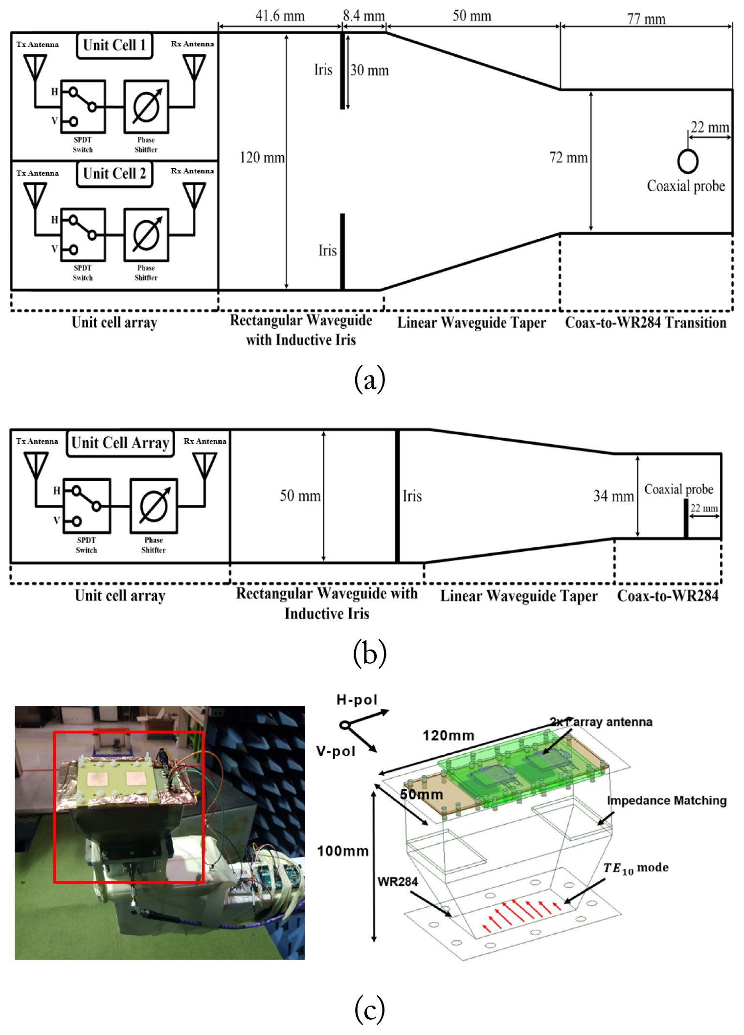
The geometry of the proposed network and its measurement setup are shown in Fig. 8. A specially fabricated waveguide is employed for unit cell verification, allowing for a seamless connection between the unit cell and the standard WR284 waveguide. The 1 ├Ś 2 unit cell array was chosen as the verification test board because it is the smallest array size for verify beam steering. The minimum dimensions of the 1 ├Ś 2 unit cell array were 80 mm in length and 40 mm in width. However, an additional 40 mm in length and 10 mm in width were included. This is because placing the 1 ├Ś 2 Rx antenna array in the center of the rectangular waveguide required an additional length of 40 mm. An extra 10-mm width was required for mechanical stability. It is important to align the 1 ├Ś 2 unit cell array to the center of the waveguide aperture because the E-field of the incident TE10 wave is applied to the 1 ├Ś 2 Rx patch antenna array symmetrically with the same polarization as the antenna.
1. Operation Principle
This section describes the operation principle of the proposed unit cell verification method using a TE10 mode rectangular waveguide. In general, multifunctional unit cells are required to simultaneously control the polarization and phase of the incident wave [31]. The proposed waveguide-fed unit cell verification method confirmed the efficiency of the unit cell, polarization conversion, and phase shift. The efficiency of the unit cell (╬Ęcell) is the ratio of the accepted power (Pa) by unit cells ((1-|╬ō|2)┬ĘPin) to the total radiated power (Pr), where Pin is the input power and ╬ō is the reflection coefficient. Thus, the efficiency of the unit cell was calculated as ╬Ęcell = Pr/[(1-|╬ō|2)┬ĘPin]. The calculated unit cell efficiency was approximately 13.2% because the loss values of the Tx/Rx antenna, switch (SW), and phase shifter (0 V) at Fs GHz were about 2.5 dB, 0.7 dB, and 3.1 dB, respectively. The polarization conversion and phase-shifting capability were easily measured by observing far-field patterns. Whereas the polarization conversion was easy to measure, the measurement of the unit cellŌĆÖs phase-shifting performance was challenging. The phase-shift performance was measured indirectly by observing the radiation patterns of a waveguide-fed 1 ├Ś 2 unit cell array.
A shunt inductive iris was connected in parallel to match the 1 ├Ś 2 unit cell array to the designed 120 mm ├Ś 50 mm rectangular waveguide. A linear waveguide taper was designed to match the standard WR284 coax-to-waveguide transition to the designed rectangular waveguide. In this work, linear taper and rectangular waveguide structures were made of aluminum. The linear waveguide taper shown in Fig. 8(a) was designed to transfer a dominant TE10 mode wave from the standard WR-284 to the designed 120 mm ├Ś 50 mm rectangular waveguide while suppressing mode conversion and higher-order mode excitation [32, 33]. The linear tapered matching waveguide section was designed for TE10 single-mode operation using coupled-mode theory. The coupled-mode theory based on a cross-sectional method is a powerful design procedure for waveguide matching networks; thus, the total E- and H-fields along a general non-uniform waveguide structure can be calculated [34ŌĆō36]. When a given waveguide structure operates in a single mode, the complex amplitude of forward (a+) and backward (aŌłÆ) traveling waves associated with the propagation modes can be determined by a simple coupled-mode equation system, which is a strong function of the coupling coefficient (K) between those waves [35]. The K value of a rectangular waveguide for TE10 single-mode operation having a propagation constant of ╬▓10 was calculated analytically, as shown in Eq. (3) [37].
where a(z) and b(z) are the width and height along the z-direction, respectively. Eq. (3) clearly shows that the rate of change in the width or height profile along the wave propagation direction is an important design factor for the waveguide taper design. In this study, a single-mode rectangular waveguide taper with simultaneous variations in height and width was designed to match the 120 mm ├Ś 50 mm rectangular waveguide to the WR-284 standard. An inherent port mismatch level (Žü0), which is a function of the difference between the cross-sections, was set to a value less than ŌłÆ15 dB (Žü0 < ŌłÆ15 dB). The length of the linear waveguide taper was 50 mm, as shown in Fig. 8. The designed 120 mm ├Ś 50 mm rectangular waveguide had three available propagation modes of TE10, TE20, and TE01 around the operation frequency (Fs), but the mode conversion level (TE10-to-TE20, and TE10-to-TE01) was less than ŌłÆ31 dB.
2. Experimental Results
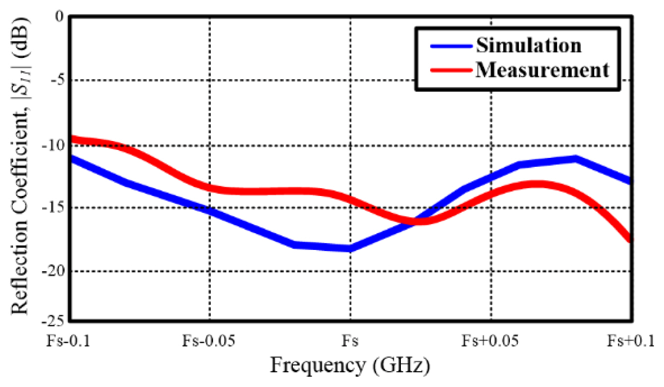
The fabricated waveguide-based feeding structure for the 1 ├Ś 2 unit cell array was 50 mm ├Ś 120 mm ├Ś 100 mm, as shown in Fig. 8(c). The designed rectangular waveguide structure was compatible with the WR-284 standard. A shunt inductive iris matched the 1 ├Ś 2 unit cell array to the coax-to-WR-284 waveguide transition. The measured reflection coefficient (|S11|) of the designed rectangular waveguide-fed 1 ├Ś 2 unit cell array is shown in Fig. 9. We observed a discrepancy between the measurements and simulations, which can be attributed to fabrication errors in the customized waveguide. However, despite this discrepancy, both the measured and simulated data exhibited a similarity below ŌłÆ10 dB at the operating frequency, suggesting tight coupling between the Rx antennas and the waveguide. The rectangular waveguide-fed 1 ├Ś 2 array was measured in the anechoic chamber like Tx/Rx antennas, and the measured ╬Ęcell was 14.7% (ŌłÆ8.4 dB) with an input power of 30 dBm (Pin = 1 W). This was calculated by taking the ratio of the total radiated power to the power delivered to the array, as discussed in Section III-1. The measured total radiated and delivered power were 142.0 mW and 968.4 mW, respectively. This was very close to the theoretical efficiency of 13.2% of the unit cell discussed in Section III-1. As previously mentioned, the input power was tightly coupled and delivered to the unit cell without being reflected. Therefore, the measured efficiency can be regarded as the element loss (EL) of the full transmitarray antenna. The loss of the transmitarray antenna (╬Ąloss) is calculated as shown in Eq. (4) [31]:
where ╬Ęspill and ELavg are spillover efficiency and element loss, respectively. ╬Ęspill is the ratio of accepted power to total power radiated by the feed, and it was calculated to be ŌłÆ2.3 dB using Ansys High-Frequency Structure Simulator (HFSS). The proposed verification was compared with the losses per component, as shown in Table 1. The total transmitarray loss (╬Ąloss) of the simulation was ŌłÆ11.1 dB, and the proposed method was ŌłÆ10.7 dB. The measured ╬Ąloss values of a fabricated 8 ├Ś 8 transmitarray antenna composed of the presented unit cell were ŌłÆ10.75 dB [24]. A comparison of the measured ╬Ąloss with the simulated losses showed good agreement, but the loss of the proposed method (ŌłÆ10.7 dB) more strictly predicts the measured value (ŌłÆ10.75 dB). Therefore, the proposed verification method provides useful information on the design and optimization of a full-sized multifunctional transmitarray or metasurface.
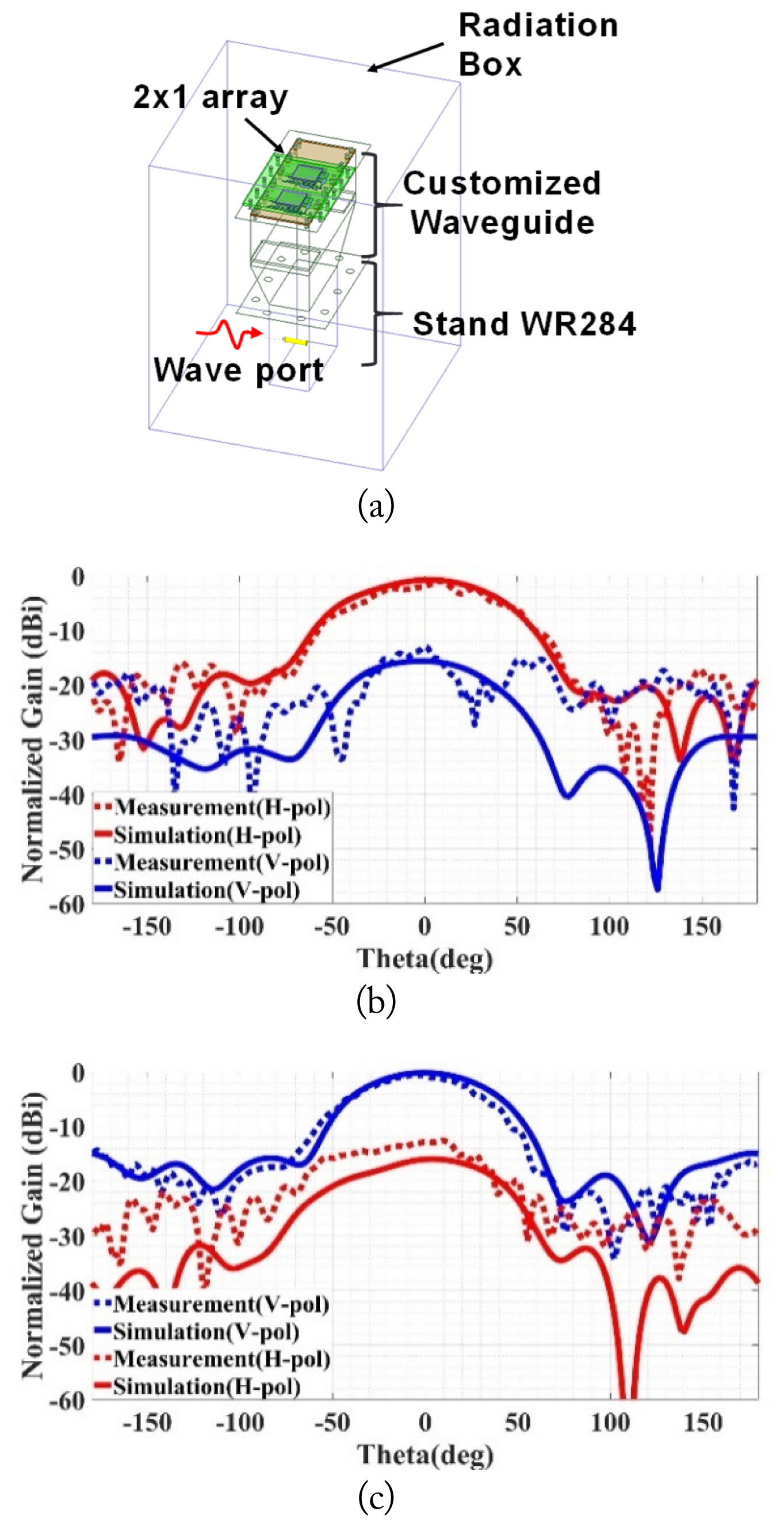
The simulation setup for unit cell verification is depicted in Fig. 10(a) and performed using HFSS. The standard WR-284 waveguide, excited by the waveport of a coaxial cable, was included in the model. A customized waveguide was positioned between the 2 ├Ś 1 array and the modeled WR-284, and the entire model, enclosed within a radiation box, was simulated. Fig. 10(b) and 10(c) show the radiation patterns of the waveguide- fed 1 ├Ś 2 array when there were no phase differences between the unit cells. The simulation and measurement data agreed very well. The polarization conversion capability was clearly observed, and the measured cross-pol suppression levels for both the V-to-V-pol and V-to-H-pol conversion cases were about 15 dB. The rectangular GND (ground) shapes had a difference between Fig. 10(a) and 10(b) because the GND lengths of the Tx antennas for V-pol and H-pol were asymmetric. Fig. 11 shows the measured beam steering capability for V-to-V and V-to-H polarization conversions. The ┬▒ 25┬░ beam steering was achieved when the bias voltage for the phase shifter was 1.9 V, corresponding to a 90┬░ phase shift. These results show that the proposed unit cell verification method successfully characterized all electrical properties, such as polarization conversion, phase shifting, and efficiency of a unit cell or a full-sized multifunctional transmitarray.
Table 2 displays a performance comparison between the proposed unit cell and the literature-reported transmitarray antennas. The results show that our proposed unit cell features a smaller size and higher phase resolution compared to other literature-reported transmitarrays. This confirms the superior performance of our proposed unit cell in terms of size reduction and phase control. In addition, conventional verification using a double waveguide structure and the proposed verification were compared, as shown in Table 3. Notably, all electrical properties of a multifunctional unit cell, such as unit cell loss, polarization conversion, relative phase shift, and far-field radiation patterns, can be experimentally verified through a one-time measurement. It is also possible to measure cross-pol suppressing levels. The rectangular waveguide structure of conventional verification methods supports only a single dominant mode at the operating frequency. The conventional closed waveguide structure for unit cell verification has limitations in measuring polarization conversion capability.
IV. Conclusion
This paper presents the structure of a unit cell for a multifunctional transmitarray and its verification method using a rectangular waveguide structure. The unit cell can simultaneously manipulate the phase and polarization of incident waves. The functionality of the designed unit cell was verified by using a 2 ├Ś 1 unit cell array fed by a rectangular waveguide structure. The 2 ├Ś 1 unit cell array was fed by a TE10 mode wave whose polarization was matched to the Rx antennas. The performance of a unit cell, such as phase shifting and polarization conversion capabilities, was measured and verified using the proposed method. The proposed verification method is a promising candidate that can be used as a unit cell verification for multifunctional transmitarrays with polarization conversion and beam steering functions.