I. Introduction
Unlike traditional wire transport technology, wireless power transfer (WPT) is a novel approach to transmitting energy through free space [1ŌĆō4]. To adapt to diversified WPT scenarios, different types of transmitting antennas have been proposed, such as wearable [5], implantable [6], electrically small [7], and reconfigurable [8]. To improve the transfer efficiency of a WPT system in the 5.8 GHz ISM band, antennas with high gain and planar structures are urgently required [9]. A high-gain antenna can reduce transmitting power and hence simplify a transmitter configuration. A planar antenna can be easily integrated into a TX/RX end and make a system more compact.
Nowadays, many transmitting antennas with high gain and planar structures have been used in WPT systems [10ŌĆō14]. By adopting a superstrate, a high-gain array antenna working in its high-order mode has been proposed [10]. Due to the reflection of the metal ground and the concentration of the superstrate, the boresight gain was up to 24.2 dBi. Similarly, the Luneburg lens is employed as an artificial dielectric superstrate to improve the peak gain of the horn-like antenna [11]. The peak gain was up to 17.2 dBi. To implement a WPT experiment in any three-dimensional space, a transmitting antenna array with 8 ├Ś 8 elements was designed [12].
In 2019, a double-sided S-shaped gradient-refractive index metamaterial (GRIN MM) unit cell was designed to enhance radiation in the far field; hence, the gain was promoted [13]. In 2022, a dual-polarized hybrid antenna was proposed for both radio frequency-energy harvesting (RF-EH) and WPT applications [14]. In that work, a 2 ├Ś 2 patch array was designed, and the gain was up to 11.8 dBi.
In the last few years, substrate-printed antennas and grid antennas have attracted many designers due to the advantages of low price, small size, suitability for mass production, and ease of integration [15ŌĆō24]. By forming an array with substrate-printed elements, both high gain and high integration can be obtained simultaneously. Additionally, the characteristic mode (CM) theory has developed rapidly in recent years [25ŌĆō29]. Characteristic mode analysis (CMA), based on CM theory, provides novel insights into the working mechanism of an antenna structure. Hence, analyzing and guiding antenna design by adopting CM theory has become a priority for antenna developers.
In this current study, the objective was to design an I-shaped slot grid antenna array with planar substrate integration and enhanced bandwidth for a 5.8 GHz WPT application. The main innovations are listed below. First, a transverse stub was introduced to produce a new resonant point; hence, the bandwidth was enhanced. Second, four gaps were etched to refine the in-band impedance matching. Third, CMA was implemented to analyze the surface current distribution of the grid antenna. Also, two pieces of substrates were integrated to make the antenna compact, and an I-shaped slot was adopted as the basic radiation element to obtain more design freedom when compared with a rectangular slot. A microstrip line was introduced to make the front-end feeding circuit easily printed on the back of the antenna. Finally, the operating band of the proposed array could cover the 5.8 GHz ISM band (5.725ŌĆō5.875 GHz). The measured peak gain was up to 11.3 dBi. Simulation and measurement results agreed well with each other.
II. Antenna Geometry
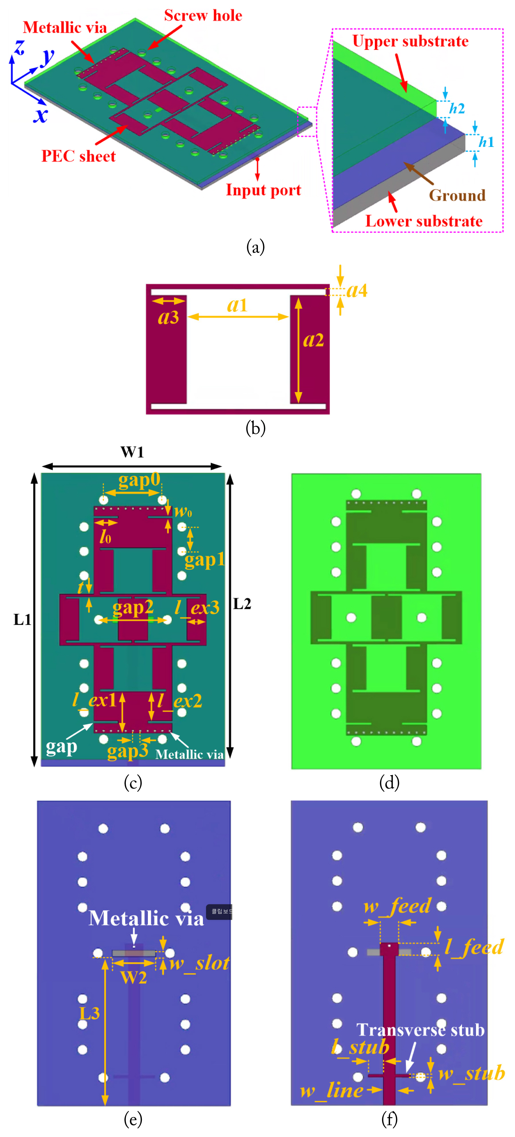
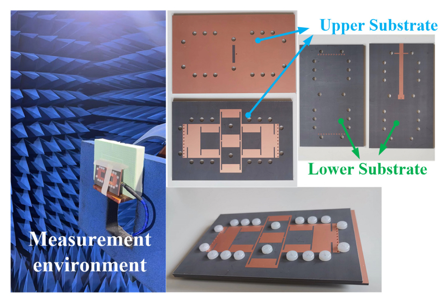
The overall view of the proposed grid antenna array is presented in Fig. 1(a). The main structure was composed of two pieces of Taconic TLX substrates with relative permittivity ╔ør = 2.55. By punching eighteen screw holes in different locations, the two substrates were spliced together by nylon screws. A perfect electric conductor (PEC) sheet was printed on the top face of the upper substrate. Four identical I-shaped slots were etched on the sheet; hence, a grid structure was formed, as shown in Fig. 1(c). An enlarged view of the I-shaped slot is shown in Fig. 1(b). Four gaps were etched on the edge of the PEC sheet to refine impedance matching. The bottom face of the upper substrate is shown in Fig. 1(d), on which no metallic layer is printed. Additionally, twenty-two metallic vias were punched in the upper substrate to connect the PEC sheet to the ground. The top face of the lower substrate is the ground layer, as shown in Fig. 1(e). An aperture was etched on the ground layer to couple the electromagnetic (EM) signal to the top PEC sheet. On the bottom face of this substrate, a microstrip line with 50 ╬® characteristic impedance was printed to receive the signal from the front-end feeding circuit, as shown in Fig. 1(f). The overall electrical size is 1.45╬╗ ├Ś 2.32╬╗ ├Ś 0.06╬╗ (╬╗ is the wavelength in free space at 5.8 GHz).
To avoid an open state at the end of the microstrip line, a metallic via was punched on the lower substrate; hence, the microstrip line and ground were electrically connected. Furthermore, a transverse stub was added to the microstrip line to obtain a wider impedance bandwidth. By simulation and optimization, the final dimensions of the antenna are listed in Table 1.
III. Simulation and Analysis
To show the EM characteristics, the proposed antenna was built and simulated in commercial simulation software, High-Frequency Structure Simulator (HFSS). In this section, bandwidth enhancement, CMA, and radiation mechanisms are discussed in sequence.
1. Bandwidth Enhancement
To demonstrate bandwidth enhancement and refinement, the antennas with/without the transverse stub and gaps were simulated and compared simultaneously.
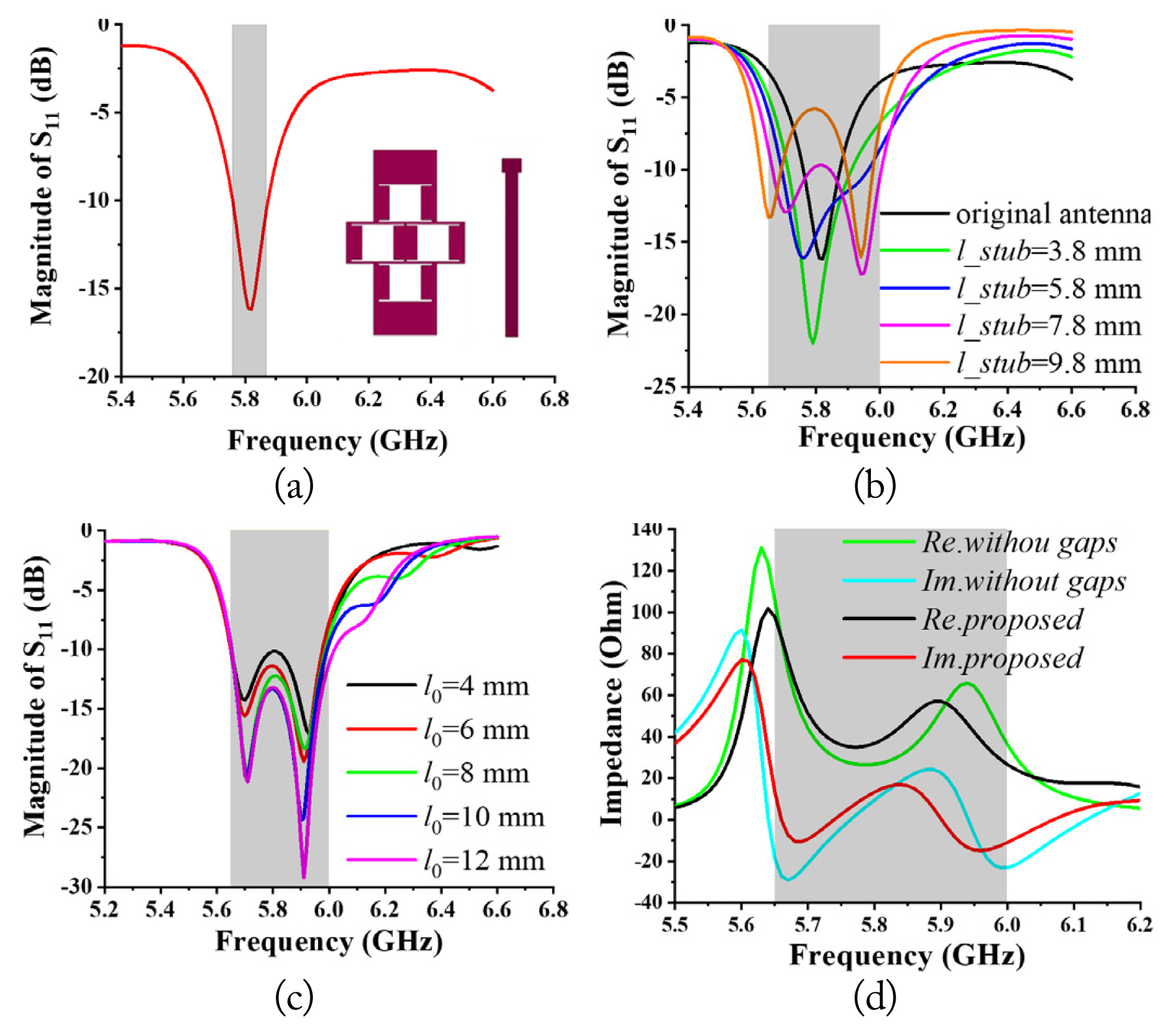
For simplicity, the antenna without the stub and gaps is called the original antenna. |S11| of the original antenna is shown in Fig. 2(a) with an illustration of the PEC sheet and microstrip line. Only one resonance occurred at 5.8 GHz in the plot. The relative bandwidth for |S11| < ŌłÆ10 dB is 1.9% (5.76ŌĆō5.87 GHz). To improve the bandwidth, a transverse stub was added to the microstrip line. As shown in Fig. 2(b), the length (l_stub) of the stub has a significant influence on |S11|. With the increase of l_stub, one more resonant frequency appears at 5.95 GHz, and the original resonant point moved to 5.7 GHz. Here, l_stub = 7.8 mm was adopted in the design, and the relative bandwidth was expanded to 6% (5.65ŌĆō6 GHz) for |S11| < ŌłÆ10 dB, as shown by the pink curve in Fig. 2(b).
Also, four gaps (as shown in Fig. 1(c)) were etched on the PEC sheet to refine the impedance from 5.65 GHz to 6 GHz. As shown in Fig. 2(c), the influence of these gaps on |S11| was plotted. |S11| in-band (5.65ŌĆō6 GHz) becomes smaller when l0 increases from 4 mm to 10 mm. While, |S11| almost keeps the same when l0 further increases to 12 mm. So, l0 =10 mm is adopted in the design. To physically explain the refinement, the input impedance of the antennas with and without gaps is plotted in Fig. 2(d). In the concerning band (brown region), the black and red curves are more converged and closer to 50 ╬® and 0 ╬® when compared with the green and blue ones. In other words, these gaps compress the real and imaginary parts of the input impedance to 50 ╬® and 0 ╬®, respectively. Therefore, the bandwidth of the original antenna was enhanced and refined with the existence of a transverse stub and gaps. The final operating band ranges from 5.65 GHz to 6 GHz, which covers the transmitting frequency of 5.8 GHz in WPT.
2. CMA and Surface Current
Early CM theory is known to solve the electric field integral equations for a perfect electric conductor [25ŌĆō29]. The equation involves a boundary condition of the perfect conductor, which can be presented by
where L(┬Ę) is an integro-differential operator to express the scattering field in terms of the current and can be written as follows:
In Eq. (2)k0 and ╬Ę0 are the wavenumber and wave impedance in free space. G(r, rŌĆ▓) is the GreenŌĆÖs function multiplied by 4ŽĆ in free space. By implementing a moment method to solve Eq. (1), the characteristic current on the surface of a scattering object can be obtained.
To explore the feasibility of the characteristic mode theory for the proposed antenna structure, CMA was adopted to analyze the surface current distribution and working mechanism at 5.8 GHz. According to the CM theory, the realistic total current (or radiation fields) can be decomposed into several characteristic currents (or characteristic fields) that are orthogonal to each other. In other words, characteristic modes (characteristic current or field) form a set of orthogonal basis vectors for any total current or total field distribution that may exist on an object. The decomposition can be mathematically explained by
where J and Jn are the realistic total current and characteristic current, respectively. ╬▒n is the weighted coefficient of Jn.
As a key index in CMA, mode significance (MS) shows how easy it is for one mode to be motivated and is defined as
where ╬╗n is the characteristic value of mode n, and MS is a real number between 0 and 1. For one mode, if its MS is near 1, this means that this mode is easy to excite. On the contrary, the mode is hard to be excited when its MS is close to 0.
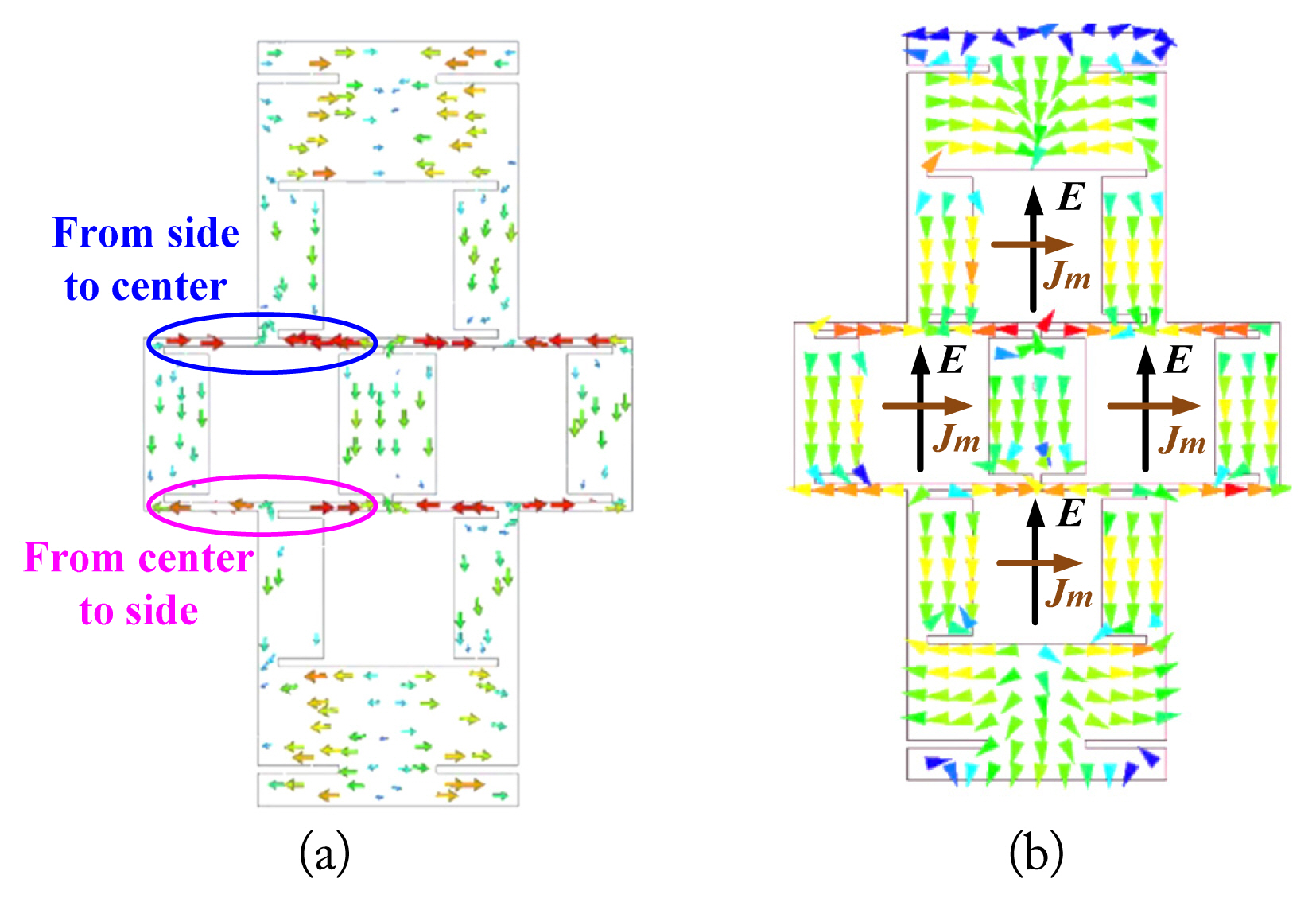
As shown in Fig. 3, the MS of the first seven modes for the proposed grid antenna array is plotted. Three modes (mode 1, mode 5, and mode 7) with large MS (>0.707) are located at 5.04 GHz, 5.4 GHz, and 5.8 GHz, respectively. This means that the above three modes can easily be excited at these frequencies. Here, 5.8 GHz (black dash line) is located within the operating band of the proposed array. Thus, the working mechanism at 5.8 GHz can be explained through the characteristic current of mode 5. As shown in Fig. 4(a), the characteristic current at 5.8 GHz of mode 5 on the PEC sheet is plotted. The characteristic current on the upper edge of the I-shaped slot flows from side to center. The characteristic current on the lower edge flows from center to side. For comparison, the total current flow is plotted in Fig. 4(b). The characteristic current distribution of mode 5 is very similar to that of the total current distribution at 5.8 GHz. Therefore, it is concluded that the total current on the PEC sheet is dominated by mode 5. Other modes have little contribution to the total current at 5.8 GHz.
Also, the working mechanism of the I-shaped slot grid array can be seen equivalently as a magnetic dipole array with four elements. The general mathematical relationship between the equivalent magnetic current and the E-field in a slot can be expressed by
where n is the normal direction of the slot. As shown in Fig. 4(b), the E-field in slots is marked by a black arrow, and the corresponding equivalent magnetic current is marked by a brown arrow.
Therefore, the working mechanism of the proposed I-shaped slot grid array is divided into two aspects at 5.8 GHz. On the one hand, the total surface current distribution on the PEC sheet was dominated by the characteristic current of mode 5. On the other hand, the radiation from the grid slots can be equivalent to the radiation of the magnetic dipole array, which will be discussed in the next section.
3. Radiation Mechanism Analysis
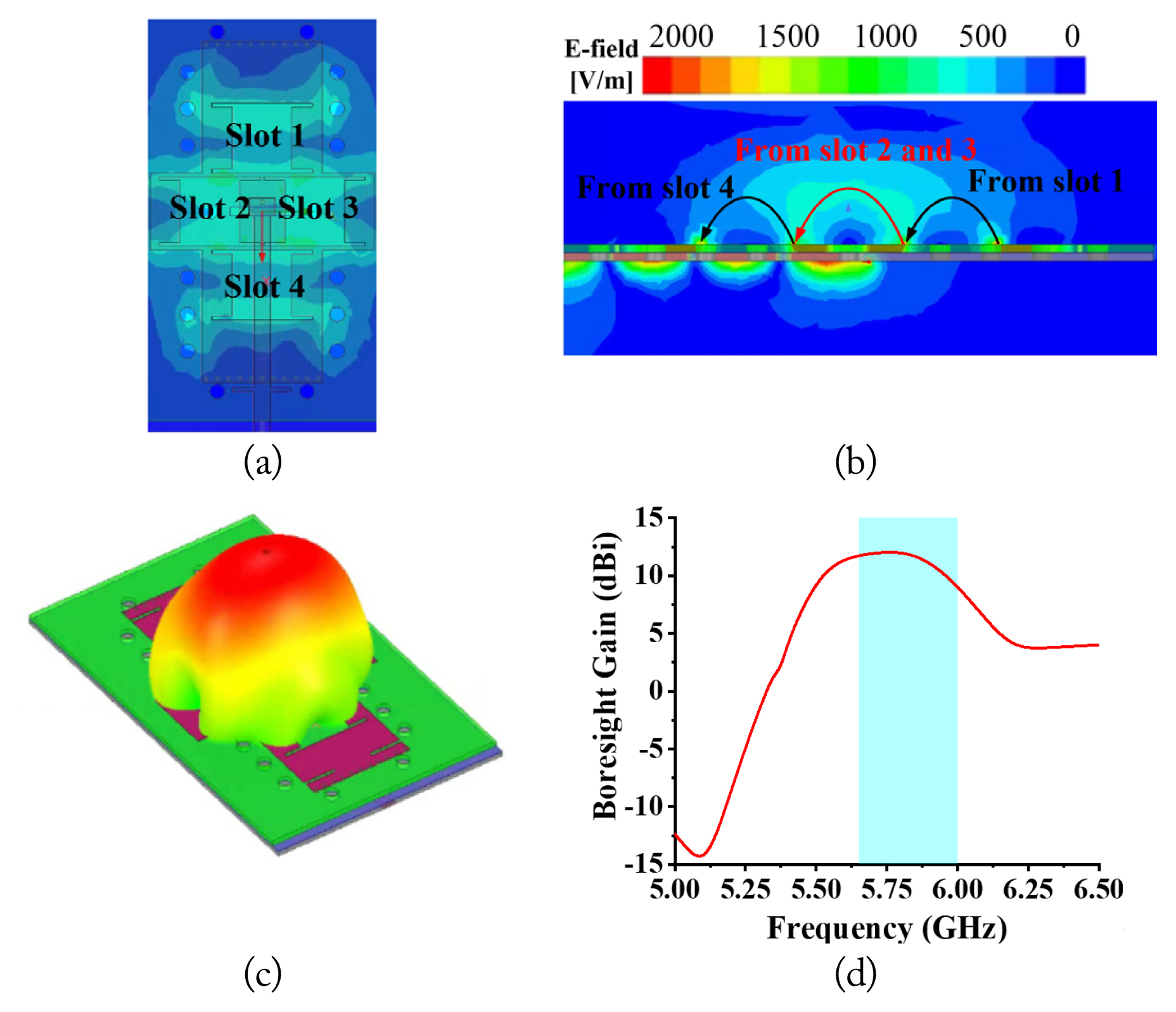
In this section, the radiating E-field at 5.8 GHz is discussed to explain the radiation mechanism. For simplicity, four I-shaped slots are named slot 1, slot 2, slot 3, and slot 4, respectively. The radiation field on the headroom of the antenna is shown in Fig. 5(a) and 5(b). From the top view in Fig. 5(a), four slots radiate their EM waves individually. The E-field from slots 2 and 3 is stronger than that from slots 1 and 4. From the side view in Fig. 5(b), the E-field from slot 1 and slot 4 is coupled to that of slot 2 and slot 3 after they depart from the surface of the antenna; hence, total boresight (z-axis in Fig. 1(a)) radiation is obtained. The boresight radiation was also validated by its 3D pattern, which is shown in Fig. 5(c). From the plot, maximum radiation occurs at the boresight of the antenna, and the gain is up to 12 dBi. The curve in Fig. 5(d) shows that the gain on boresight ranges from 9 dBi to 12 dBi in the blue zone. This guarantees stable boresight radiation across the entire operating band.
IV. Fabrication, Measurement, and Validation
To validate the design, a prototype was fabricated through a multi-layered substrate lamination technique. The PEC sheet was realized by copper plating. As shown in Fig. 6, the antenna was put into an anechoic chamber to measure its EM properties. The voltage standing wave ratio (VSWR) was obtained using the Agilent vector network analyzer N5230A.
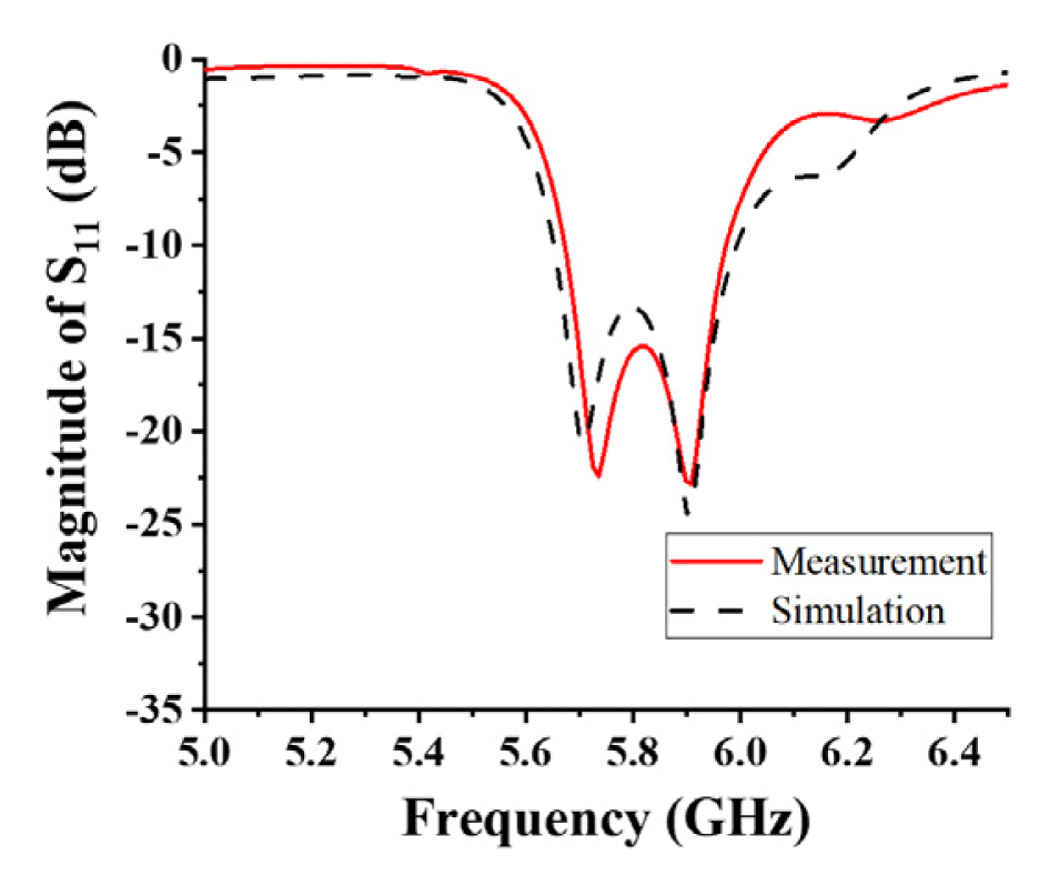
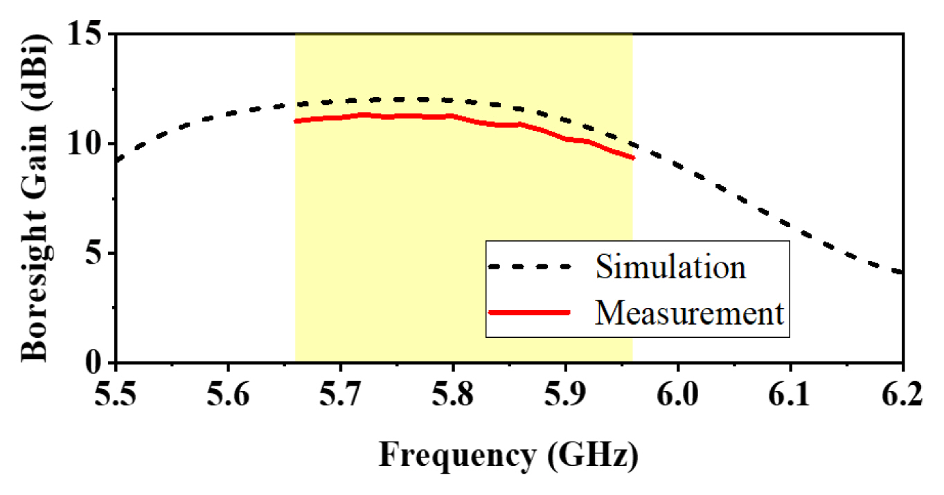
As shown in Fig. 7, it is seen that the measured |S11| is less than ŌłÆ10 dB from 5.67 GHz to 5.96 GHz. Two resonant points are observed at 5.71 GHz and 5.89 GHz. Measured |S11| agreed well with the simulation. Fig. 8 gives both the simulated and measured normalized radiation patterns at 5.8 GHz. Due to the limitation of our measurement environment, the measured angle is constrained between ŌłÆ90┬░ and +90┬░. From the patterns in both the E- and H-planes, the maximum radiation directs at the boresight of the antenna plane, and good agreement is observed between the simulation and the measurement. On the boresight, the measured cross-polarization level of measurement is less than ŌłÆ30 dB. A comparison between the simulated and measured gains on boresight is given in Fig. 9. In the operating band (yellow zone), the simulated and measured gains varied from 10 dBi to 12 dBi and from 9.3 dBi to 11.3 dBi, respectively. Peak gain (11.3 dBi) in measurement occurred at 5.76 GHz. The measured gain was 0.7 dB lower than that of the simulation, and the difference can be attributed to the substrate losses. According to the above discussion, the measurements and simulations agree well with each other, and the feasibility of the design is validated. The slight difference is caused by fabrication, installation, and measurement errors.
To show the performance advantage of the proposed antenna, Table 2 compares the proposed antenna and other related antennas. From the comparison, it is obvious that studies [11], [13], and [30] have a wider bandwidth. However, the transverse sizes in [11] and [30] are more than 3╬╗ 0 (╬╗ 0 is the center wavelength). The profile in [13] is higher than 2╬╗ 0. Our work had a size of only 2.3╬╗ 0 ├Ś 1.45╬╗ 0 ├Ś 0.06╬╗ 0. Hence, despite a little sacrifice in bandwidth, the antenna used in this research needed less occupation space when compared with studies [11], [13], and [30]. A 6% bandwidth is enough to implement a WPT in the 5.8 ISM band. Several studies [5, 10, 14, 31] have narrower bandwidths than in our work. Furthermore, only a 5 dBi gain was obtained in [31]. A study of Chang et al. [5] has a maximum gain of only 2.71 dBi, and its bandwidth is only 4.6%.
Based on a fair comparison, our antenna had a good comprehensive performance (improved bandwidth, moderate gain, and smaller sizes) in the WPT system.
V. Conclusion
A planar substrate-integrated I-shaped slot grid antenna array was designed, fabricated, and measured. Two pieces of substrates were integrated to realize a compact structure. Four I-shaped slots were formed on the top PEC sheet to obtain a boresight high gain. A transverse stub and four narrow gaps were introduced to improve and refine the bandwidth. The working mechanism at 5.8 GHz was analyzed with the help of CM theory. Through measurements, the proposed antenna array exhibited good electrical properties in the 5.8 GHz ISM band. The measured bandwidth for |S11| < ŌłÆ10 dB was 5% (5.67ŌĆō5.96 GHz). The gain on boresight varied from 9.3 dBi to 11.3 dBi in the operating band. The cross-polarization level was less than ŌłÆ30 dB. Therefore, the proposed design is suitable for use as a transmitting antenna in a WPT system and in other scenarios with the requirements of planar, high integration, and high gain.