Directional Monopole Antenna Using a Planar Lossy Magnetic (PLM) Surface
Article information
Abstract
A directional monopole antenna using a planar lossy magnetic (PLM) surface is proposed in this paper. When a monopole antenna is designed vertically on the ground plane composed of a perfect electric conductor (PEC) and a perfect magnetic conductor (PMC), the surface current on the ground plane cannot flow on the PMC and only flows in one direction on the PEC. Therefore, the electromagnetic (EM) wave of such a monopole antenna can radiate in the direction perpendicular to the ground. Alternatively, a PLM surface such as a ferrite sheet with a high relative permeability was employed to achieve EM properties similar to the PMC. To verify the feasibility of the proposed antenna, a ferrite sheet with a relative permeability of 20 and a magnetic loss tangent of 10 at 2 GHz was utilized to implement the half PMC ground plane, and the monopole antenna was bent for miniaturization. The measured peak gain and the −10 dB bandwidth was about 1.3 dBi and 23% at the resonant frequency, respectively.
I. Introduction
Generally, a microstrip patch antenna is an attractive and competitive solution for wireless communications due to its low fabrication cost, simple structure, directivity, and low-profile design. However, it typically has a narrow fractional bandwidth of about 1%–5%. A variety of methods have been proposed to increase bandwidth, such as intrinsic techniques, aperture-coupled patches, stacked patches, and horizontally coupled patches [1]. On the other hand, wire antennas classified as dipole, monopole, helical, or loop are also the most useful antennas for many applications. Lastly, the wire antenna presents a wide impedance bandwidth and an omni-directional radiation pattern (except for the helical antenna in axial mode) [2, 3].
In this research, a monopole antenna having both the directional radiation pattern of a patch antenna and the broad bandwidth of a wire antenna was designed using a hybrid ground plane composed of one-half perfect magnetic conductor (PMC) and one-half perfect electric conductor (PEC). Since surface currents do not flow on the PMC ground, the surface current on the PEC ground cannot be canceled out in all directions and flows in one direction; therefore, the electromagnetic (EM) wave of an antenna radiates directionally. A planar lossy magnetic (PLM) surface was employed to realize the PMC ground simply instead of an electromagnetic band gap (EBG) [4] structure or a corrugated soft surface [5]. In Section II, the operation principle of the proposed directional monopole antenna and the EM properties of the PLM surface are described. The simulated and measured results of the proposed directional bent monopole antenna are discussed in Section III. Finally, the conclusions are presented in Section IV.
II. Design of Directional Monopole Antenna
Fig. 1 shows the surface current distributions of monopole antennas with PEC ground and PMC/PEC ground with dimensions of 1λ0. When the monopole antenna is on PEC ground with dimensions of 1λ0, the surface current on a ground plane is canceled out because the current symmetrically spreads out to the border of the ground. For this reason, monopole antennas generally have an omnidirectional radiation pattern. In the case of a monopole antenna with ½ PMC and ½ PEC ground, only the horizontal current (indicated by a solid red line) remains due to the high impedance property of PMC, as shown in Fig. 1(b). This type of current distribution produces a directional radiation pattern perpendicular to the ground [6]. Since PMCs do not exist in nature, artificial structures such as EBGs and soft surfaces are required to utilize the high impedance property of PMC. However, the EBG structure is difficult to design and has a narrow high-impedance range. In addition, soft surfaces could be bulky due to their depth of a quarter wavelength.
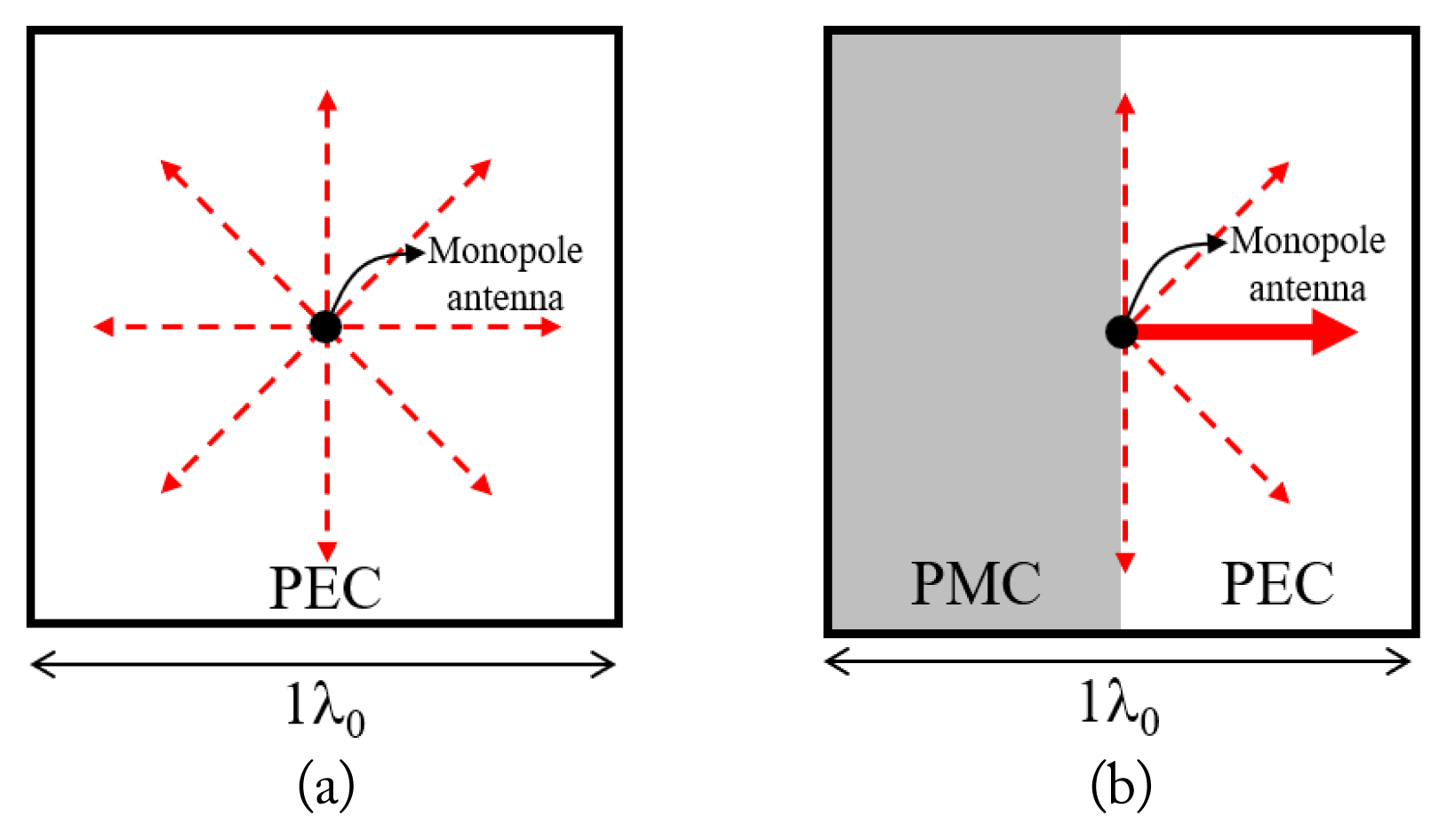
Surface current distribution of monopole antenna on ground plane: (a) PEC ground and (b) half PMC/PEC ground.
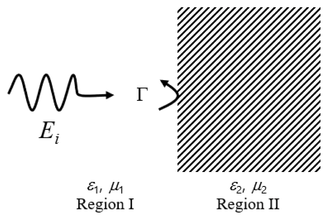
In our approach, we realized PMC ground using a ferrite sheet with high relative permeability and magnetic loss tangent. When a plane wave is generated and propagates from region I is incident normally at the interface between air and material, as shown in Fig. 2, the reflection coefficient (Γ) can be expressed as follows:
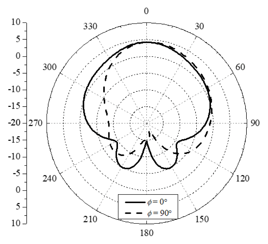
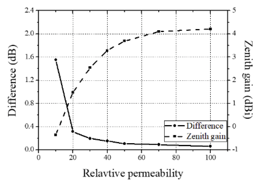
where ɛ1(ɛ2) and μ1(μ2) are the relative permittivity and permeability at region I (II), respectively. If the relative permeabilities of region I and region II are 1 and infinite, respectively, then the reflection coefficient is 1. In other words, the amplitude and phase of the reflection coefficient are 1 and 0°, respectively. Thus, when the plane wave is incident from the air into the ferrite with relatively high permeability, the reflection property of the ferrite is nearly the same as that of a PMC. To verify its feasibility, we simulated the proposed antenna with half ferrite sheet ground using commercial ANSYS Electronics Desktop software. The relative permeability and magnetic loss tangent of the utilized ferrite were 100 and 1, respectively. In addition, the ferrite sheet should be located above the PEC ground to maximize directivity. The operation frequency is 2 GHz, and the ground dimension is 150 mm × 150 mm. Figs. 3 and. 4 show the full-wave simulated reflection coefficient and the far-field radiation pattern of the directional straight monopole antenna, respectively. The reflection coefficient of the directional straight monopole antenna was nearly the same as that of the conventional monopole antenna because the input impedance was almost the same as that of the conventional monopole antenna. The −10 dB bandwidth was found to be about 20% and to be considerably broader than the bandwidth of the microstrip patch antenna, of which bandwidth was 1% with the same directional radiation pattern. As shown in Fig. 4, the radiation pattern at the y-z plane (φ = 90°) was slightly asymmetric due to the asymmetrical ground plane. The zenith gain (θ = 0°) and peak gain were measured at 4.2 dBi and 4.26 dBi, respectively. As the relative permeability of a ferrite increases, the difference between peak and zenith gains can be reduced, and the zenith gain can be improved, as shown in Fig. 5.

Comparison of full-wave-simulated reflection coefficients between the patch antenna and directional straight monopole antenna (μ = 100, tanδ = 1).
III. Simulated and Measured Results of the Directional Bent Monopole Antenna
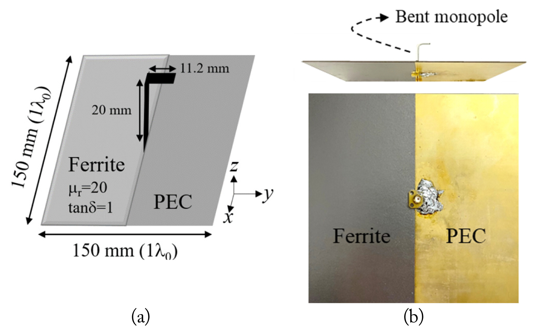
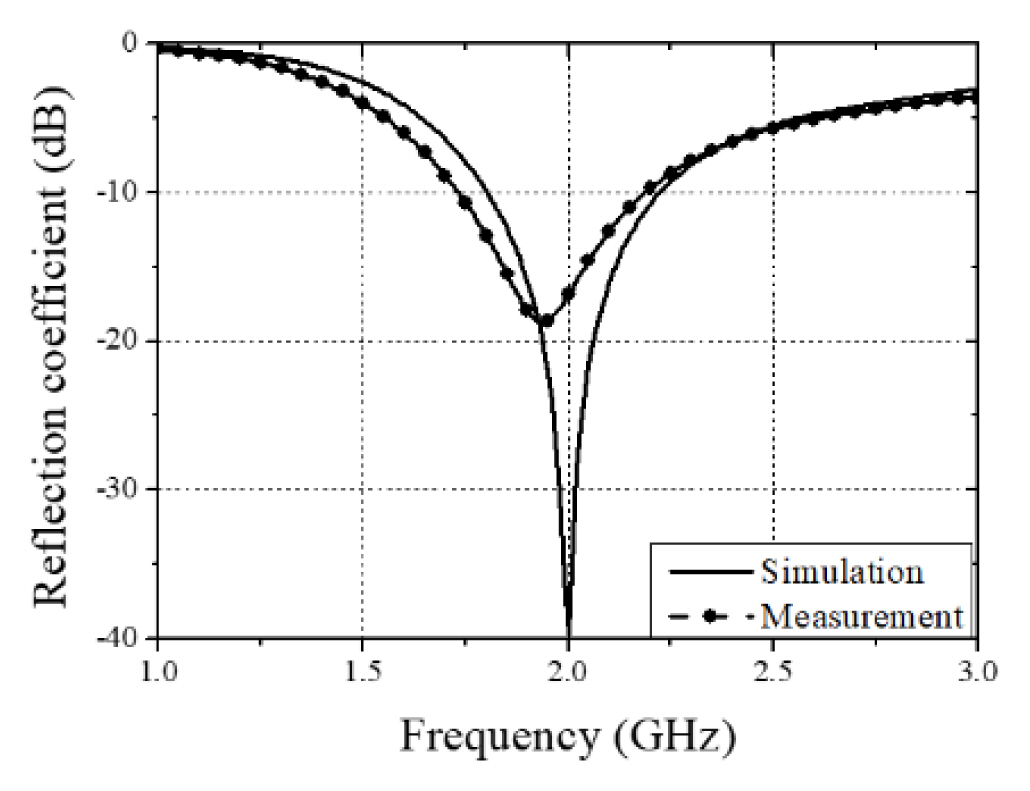
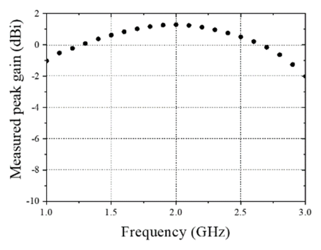
A bent monopole with a length of 31.2 mm was designed in this study to minimize overall antenna volume, as shown in Fig. 6. Also, we realized PMC ground using a ferrite sheet manufactured by E-Song EMC (Model SR35; E-Song EMC Co. Ltd., Seoul, Korea), which has a relative permeability of about 20 and a magnetic loss tangent of about 1 at 2 GHz. The ground dimensions were 150 mm × 150 mm, which corresponds to one wavelength. The simulated and measured reflection coefficients of the directional bent monopole antenna are shown in Fig. 7. The measured results were obtained using an Anritsu MS46522B vector network analyzer. The −10 dB bandwidths were measured to be 450 MHz (1.74–2.19 GHz), and the simulated and measured results were in agreement except for a down-shifted resonance frequency of 60 MHz. In addition, the far-field radiation patterns and peak gains were measured in the semi-anechoic chamber system to confirm performance. Fig. 8 shows the simulated and measured far-field radiation patterns of the proposed directional bent monopole antenna. The measured results are in good agreement with the simulated results. The zenith peak gain and peak gain were measured to be 1.29 dBi and 1.61 dBi, respectively. The radiation pattern at the y-z plane (φ = 90°) is slightly asymmetric due to the asymmetrical ground plane. The tilt angle at the y-z plane was 12° in this prototype, but it can be reduced as the relative permeability of a ferrite increases. The total efficiency is calculated to be 67%. In this study, we focused on the verification of the methodology of the proposed directional monopole antenna. If the ferrite with high permeability and low loss tangent is manufactured and employed with this kind of antenna, a broadband monopole antenna with high gain and efficiency can be designed. It is thought that current methods for manufacturing magnetic materials will increasingly be developed. Moreover, the proposed antenna would have better performance in low-frequency bands under 1 GHz. Fig. 9 shows the measured zenith peak gain versus frequency. As shown in Fig. 9, within the increased impedance band, the proposed antenna properly operates the radiation beam characteristic similar to resonance frequency. Table 1 presents a comparison of measured performances between the conventional bent monopole antenna and the proposed directional bent monopole antenna with ferrite with a relative permeability of about 20 and magnetic loss tangent of about 1. The dimensions of the conventional monopole antenna are the same as the proposed antenna. Since the conventional monopole antenna has an omni-directional radiation pattern and a finite ground plane, the peak gain angle is 38° at the x-z plane. The −10 dB bandwidth of the proposed antenna is nearly the same as that of the conventional monopole antenna. The peak gain can be increased by using a high permeability ferrite, as described in Section II. The proposed directional monopole antenna having both directivity and broad bandwidth was designed using a simple method, such as the alteration of the ground plane. Thus, it can be utilized for applications that require a directional antenna and little spatial restriction.

Simulated and measured far-field radiation patterns of the proposed antenna: (a) x-z plane and (b) y-z plane.
IV. Conclusion
A directional monopole antenna using a ferrite sheet and PEC ground plane was proposed and presented in this paper. Hybrid ground composed of a ferrite sheet and PEC gave rise to asymmetrical horizontal current flows on the PEC ground, resulting in directional radiation to the zenith. A prototype of the proposed directional bent monopole antenna was designed at 2 GHz and had total ground dimension of 150 mm × 150 mm (1λ0 × 1λ0). As a result, the peak gain and the −10 dB bandwidth are obtained to be about 1.3 dBi and 23%, respectively. The measured results lead to the conclusion that the proposed monopole antenna has the potential to be a wireless communication solution.
Acknowledgments
This work was supported by Kyungnam University Foundation Grant, 2021.
References
Biography

Jae-Gon Lee received his B.S., M.S., and Ph.D. degrees in electronic and electrical engineering from Hongik University, Seoul, Korea, in 1999, 2001, and 2007, respectively. From 2007 to 2015, he was a chief researcher at LG Electronics, and from 2016 to 2018, he was a research professor at the Metamaterial Electronic Device Research Center, Hongik University. In 2019, he joined the Department of Electronic and Software Engineering of Kyungnam University, Changwon, Korea, where he is currently an assistant professor. His research interests include metasurface/metamaterial RF devices, small antennas, and EM sensors.
