I. Introduction
Since various materials are used for electromagnetic wave applications and device development, it is imperative to understand their electrical properties as completely as possible. The electrical properties of unknown materials can be characterized into three categories: (1) The free-space method, (2) cavity perturbation, (3) the transmission line method [1]ŌĆō[4].
The free space method requires placing the MUT between two horn antennas and extracting the permittivity using the reflection and transmission coefficients. This method yields relatively accurate results, but the measurement environment configuration is relatively expensive.
This is because, in addition to measurement equipment such as the vector network analyzer (VNA) and microwave cables, the proposed method requires additional peripherals such as advanced horn antennas and microwave absorbers to minimize electromagnetic wave scattering and undesired propagation.
Second, cavity perturbation stems from the extraction of the permittivity by the difference in resonance frequency before and after inserting a sample into the cavity [2], [3]. Although advantageous in terms of being able to measure at a high temperature, the cavity perturbation method is inherently limited to narrow-band environments. Moreover, measurement at high frequencies above 10 GHz is problematic due to the difficulty of fabricating extremely high-precision cavities.
The transmission line method offers an accurate extraction over a wide bandwidth by calculating the permittivity of the substrate using the ABCD matrices of two transmission lines of different lengths [4]. However, since this is an extraction method for the substrate of the transmission line, a transmission line based on the substrate to be measured (MUT) must first be designed and fabricated. In many cases, this is unrealistic. Recently, various methods to address the aforementioned limitations have been introduced, but the methods remain limited to lower-frequency spectra [5], [6].
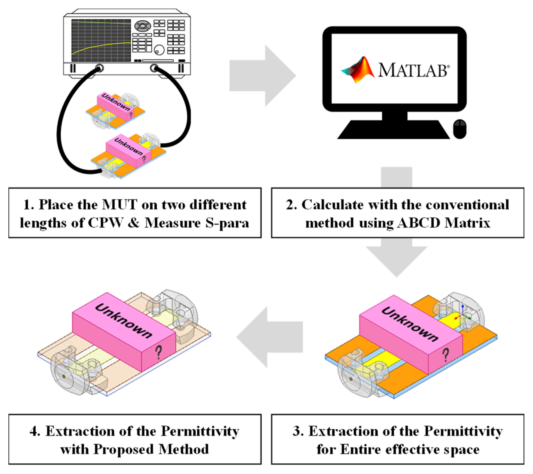
In this paper, we present a new class of permittivity extraction methods by modifying the transmission line method (TLM). This permittivity extraction technique can be performed through a relatively concise measurement configuration. In addition, the improved method extracts the permittivity of the superstrate placed on the reference line, enabling a rapid measurement process, and eliminating the need for transmission line design and fabrication process. Furthermore, unlike other recent methods using a Co-planar Waveguide (CPW), permittivity extraction is continuously possible from microwave to millimeter-wave frequency range (1.0 ~ 30.0 GHz). The flow chart of the permittivity extraction process is shown in Fig. 1 comprising the four detailed steps.
II. TLM-BASED SOLID DETECTION SENSOR
1. Principle of the Conventional Method
For ease of understanding, since the proposed method is based on TLM, the conventional method will be explained first, followed by the improved method. In Fig. 2, the ABCD matrices of two CPW lines with different lengths (ŌĆ£Line 1ŌĆØ and ŌĆ£Line 2ŌĆØ) are expressed as follows :
By using the properties of similarity and trace of the matrices, the following series of equations can be obtained [4],
Given its relationship with the phase constant ╬▓, the total effective permittivity of the CPW is defined by
by converting this effective permittivity into a relative permittivity using the formula below, the substrateŌĆÖs permittivity of the CPW line is extracted [7].
2. Principle of the Proposed Method
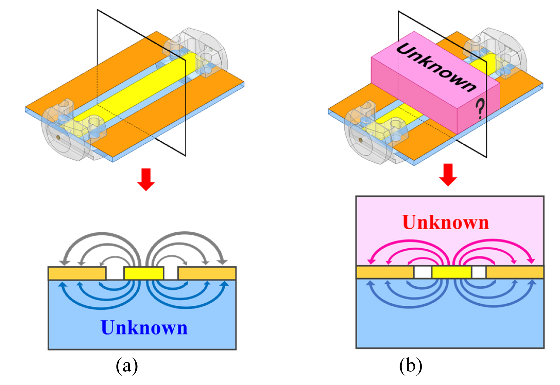
The proposed method is described as follows: by placing the MUT pieces at the T1 and T2 positions in Fig. 2 and proceeding up to (5), the effective permittivity of the entire space including the MUT was derived. In the case of the microstrip line, the E-field was concentrated on the substrate between the signal line and the ground. In contrast, in the case of the CPW, the ground is situated at the same layer as the signal line. This enables the superstrate and the substrate to independently influence the electromagnetic wave. Therefore, the results up to (5) above can be considered as the permittivity of the entire effective space, which is the sum of the permittivity of the upper substrate and the substrate. However, in general, since the superstrate of the CPW is an air medium (╔ør Ōēģ 1) as shown in Fig. 3(a), the conventional equation (6) is incompatible with the case where the MUT is placed on the CPW, as seen in Fig. 3(b). Accordingly, when the relative permittivity obtained by using (6) is ╔ør0, it should be compensated in accordance with the permittivity of air (╔ør Ōēģ 1), and the value becomes the total relative permittivity of the substrate and the superstrate.
Finally, the relative permittivity of the superstrate (= MUT) can be obtained by subtracting the relative permittivity of the substrate in which the value is known and used as a reference.
Through this principle, the permittivity of any superstrate (MUT) can be extracted with two reference CPWs with different lengths in which the permittivity of the substrate is known.
III. Results
1. Simulation Results
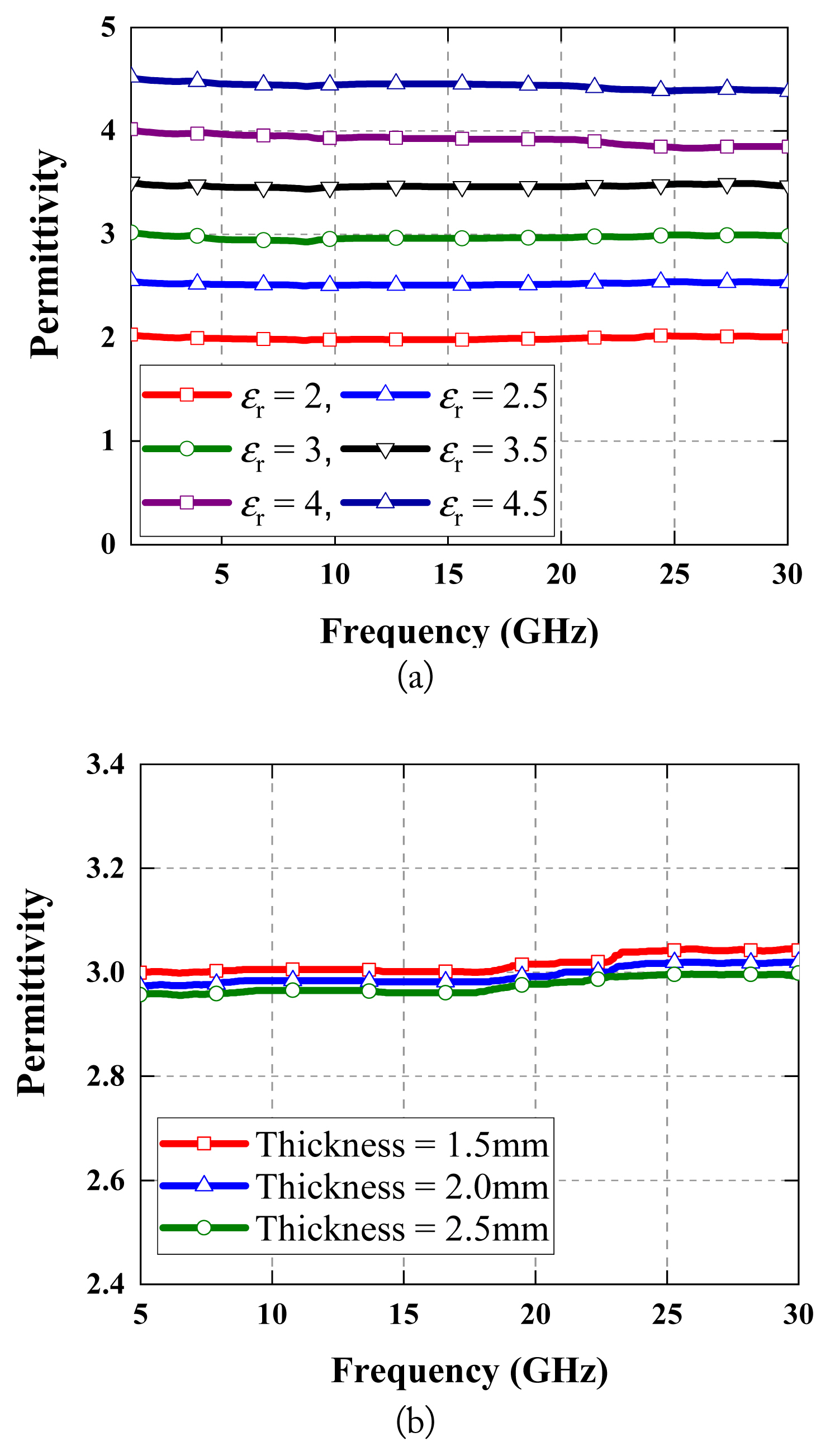
To verify the feasibility of the proposed permittivity extraction method, a series of simulations were performed. Two CPW lines of 20 mm and 30 mm lengths were used as a reference. FR4 substrates were used with copper as the metal layer (s = 0.4, w = 0.12, h = 1 mm, t = 18 um). As shown in Fig. 3 (b), the MUT is placed on the CPW line and the permittivity of the material is set in 0.5 increments from 2 to 4.5, and simulation is first performed. As shown in Fig. 4(a), a permittivity extraction with an error rate of less than 5.0% across a wide bandwidth of 1.0ŌĆō30.0 GHz was verified. However, higher permittivity confines the electric field to a greater degree. Therefore, the error rate is proportional to permittivity and becomes higher than 9.7% at a permittivity of 10. Since commonly used solid materials feature a permittivity of less than 10, the proposed method is effective in measuring most solid materials. In addition, the use of this method had no significant effect on the thickness of the MUT, as shown in Fig. 4 (b).
2. Measurement Results
The reference CPW lines used for measurement were manufactured and tested with specifications identical to those used during the simulation. VNA was used as the experimental equipment. With regard to the configuration of the measurement environment, it is imperative to minimize errors that may occur during the experiment. Generally, the primary cause of errors is the air gap, which appears mainly between the CPW and the MUT when placing the MUT on the CPW. It causes a significant error, even with its small thickness. During the measurement, the CPW line is fixed by a manufactured jig followed by polystyrene foam, which exhibits a similar permittivity to air (╔ør Ōēģ 1.1) on top of the MUT to prevent any air gaps. The overall measurement setup is shown in Fig. 5. Experiments were conducted for two types of MUTs. First, by performing an experiment with a known MUT, the extracted value and the reported value were compared. Next, an identical experiment was carried out for synthesized materials (or mixtures) with unknown permittivity. Only the volume of the material is known.
In this study, the known MUT was set as FR4, which is easily accessible. The FR4 pieces were placed on the upper side of the CPWs, as illustrated in Fig. 5. The extracted permittivity of the FR4 ranges within the reported value, as shown in Fig. 6 (a) [8]. The result was obtained over a wide bandwidth from 1.0ŌĆō30.0 GHz. In addition, the estimation using the proposed method confirmed an accuracy of over 95.0%. Next, the experiment was conducted with the MUTs that contain alumina or ATH: a MUT with 20% alumina, 30 % alumina, 20% ATH, and 30% ATH. The extracted permittivity is shown in Fig. 6 (b). The permittivity increases linearly and is proportional to the volume of each material. This tendency also proves that the proposed method is valid and effective for the characterization of random solid materials.
IV. Conclusion
For the first time, a wideband transmission line method to extract the permittivity of solid materials has been proposed and verified. This method differs from the conventional method using transmission lines, as it can characterize the permittivity on the spot without any additional manipulation of the MUT. In addition, the presented method is concise and cost-competitive, as it can be conducted with an elementary equipment setup. Full-wave simulation & measurement confirmed the validity of the proposed method, indicating that the accuracy was over 95.0% from 1.0 GHz to 30.0 GHz, which is the largest bandwidth reported. It is expected that this concept can be utilized across various scenarios that require the economic, rapid, and accurate characterization of advanced materials.