Broadband Beamforming Using the Least Square Method Improved via Adaptive Diagonal Loading
Article information
Abstract
The least square method (LSM) is a commonly used beamforming method. However, it limits the beamforming frequency bandwidth and is vulnerable to noise; therefore, diagonal loading is used to overcome these limitations. The diagonal loading proposed in this study can be used for broadband beamforming in cases in which noise does not exist, and it makes the loading factor adaptive to a singular value distribution. The simulation results show that the proposed method works stably above the beamforming frequency limit, even for an extended beamforming frequency. We expect that the proposed method can be used to form frequency-invariant beam patterns used in monopulse algorithms to detect signals of unknown frequencies.
I. Introduction
Frequency-invariant beamforming methods, such as the least square method (LSM), have been widely used for broadband beamforming [1, 2]; however, each method limits the frequency bandwidth, with or without noise. Diagonal loading (DL) has primarily been used to improve the performance of minimum variance distortionless response and linearly constrained minimum variance beamformers [3, 4]. However, to the best of the authors’ knowledge, DL with LSM has never been used to improve broadband beamforming performance.
This study aims to achieve the desired beam pattern using a 21-element broadband beamforming antenna array with a wide bandwidth. The beamforming antenna array was fixed, and the distance between the array elements was set to half wavelength at 3 GHz, and the wavelength was minimum across the beamforming frequency band from 100 MHz to 3 GHz with a step size of 100 MHz. This study proposes an improved beamforming method that expands the frequency bandwidth used for beamforming and stabilizes the beamforming performance. It uses an LSM with DL that is adaptive to singular values (SVs), which vary according to the beamforming frequencies.
II. Limitations of the Least Square Method
The LSM is a broadband beamforming method that calculates antenna array weights as follows:
where yD denotes the sampled desired beam pattern, W denotes the weight of the antenna array, and X denotes a manifold vector; thus, XTX is the steering or covariance matrix. The LSM is limited by i) the decrement of the effective aperture size as the beamforming frequency decreases and ii) vulnerability to noise.
The electrical aperture size (EAS) of the array is the product of the number of antennas and the interval between antenna elements. The interval is based on the wavelength of the beamforming frequency; therefore, the EAS is proportional to the beamforming frequency. The beamforming performance starts degrading below a certain frequency, where the EAS of the beamforming antenna array is the same as that of the array that forms the desired beam pattern [5]. We refer to this frequency as the beamforming limit frequency (BLF), which is the product of the designed frequency of the antenna array (3 GHz) and the ratio of the number of antennas required to form the desired beam pattern and broadband beamforming. For example, if there are 7 desired and 21 broadband beamforming antennas and the designed frequency is 3 GHz, the BLF is 1 GHz.
The beam pattern changes according to the noise level. The root mean square error (RMSE) of the entire normalized beam formed according to the signal-to-noise ratio (SNR) in the lower band is shown in Figure 1. Two characteristics can be observed in the figure. i) The RMSE is excessively high up to 0.9 GHz and is one step below the BLF under 10 dB and 20 dB SNR noise levels. ii) A significant error appears if noise exists, and it occurs irrespective of the BLF.
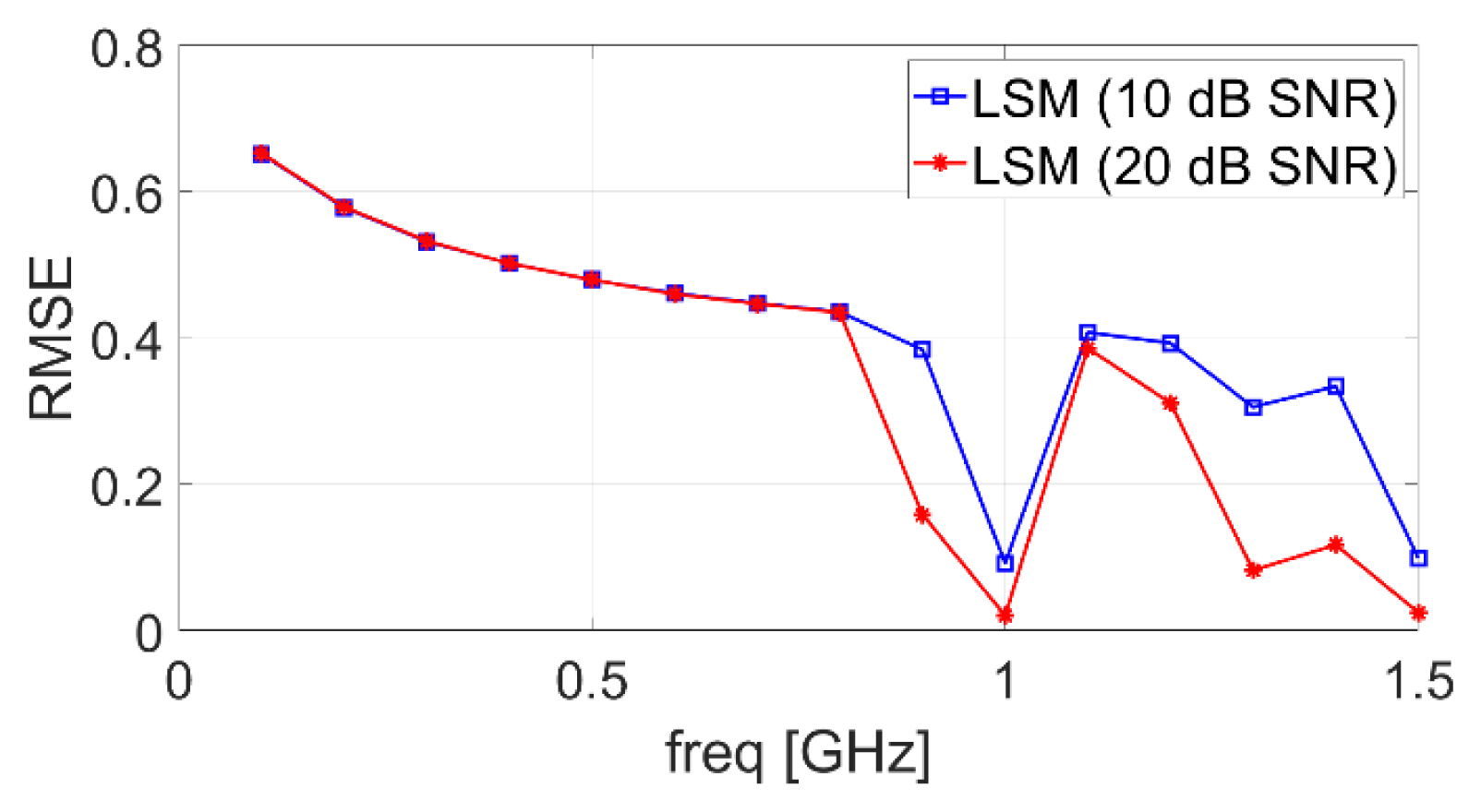
RMSE of the entire normalized beam pattern formed using LSM under 10 and 20 dB SNR noise levels
By comparing Fig. 1 and 2, it is evident that the RMSE of the entire beam pattern is highly correlated with the weight norm. The RMSE is significantly large in the frequencies wherein the weight norm is larger than −1. By decreasing the normalized weight norms, the aforementioned limitations can be overcome.

Log-scale weight norm of the conventional beamforming method
III. Proposed DL Method
DL can improve the condition number of the covariance matrix by adding a DL term to the covariance matrix [3, 6]. The DL term is αI, where I denotes the identity matrix and α denotes the DL factor. The proposed DL is different from the conventionally used DL in two ways. i) It is applied to broadband beamforming. ii) It is applied before noise is added. In contrast, conventional DL methods are primarily used for adaptive beamforming [3, 4], and DL is applied when noise exists and the DL factor is calculated and determined based on the noise [4].
In the method proposed in [3], α is determined not with the noise but with SVs, unlike in most previous studies. However, the method used in [3] has a limitation in that it maintains a constant value of α across the beamforming frequencies during broadband beamforming. In contrast, the proposed DL varies α according to the SV distributions of XTX, and its value becomes zero when the beamforming frequency is sufficiently high such that DL needs not be applied.
When all SVs of XTX in the decreasing order are λ1 > λ2 > ⋯ > λD ≫ λD+1 > ⋯ > λM, where D satisfies Eq. (2)
then the SVs from λD+1 to λM are usually considered to be noise or interference [3, 4]. In this problem, they are not noise but SVs from the low rank of XTX owing to the lower frequency band. Using an excessively large value of α would result in significant distortion in the covariance matrix, whereas using an excessively small value would not sufficiently improve the condition number. Therefore, the value of α should be between λD+1 and λM. We propose setting it to the mean of the SVs from λD+1 to λM as follows:
Thus, in contrast to [3], α becomes adaptive according to the beamforming frequency.
Moreover, when the beamforming frequency is sufficiently high, such that it is better to apply LSM without DL, it is better to maintain the DL factor as zero. Therefore, we propose that DL should not be applied when λM/λ1 is larger than 10−12.
IV. Simulation Results
The aim was to form a target beam pattern using 21 beamforming antennas in the frequency band (100 MHz to 3 GHz) under 10 dB and 20 dB SNR noise levels. The simulation was repeated 30,000 times [7]. The BLF was set to 1 GHz by considering the properties of the desired beam pattern and the number of broadband beamforming antennas. The metrics used for performance comparison were half power beam width (HPBW) and side lobe level (SLL) errors. The HPBW and SLL of the desired beam pattern were set to 14.9° and 15 dB, respectively, and each metric was calculated root-mean-square-wise for each frequency. The performance was only calculated across 0.9–1.5 GHz because good beamforming performance was obtained without DL in bands above 1.5 GHz, whereas the beamforming did not work well in the low-frequency band if noise existed, regardless of DL.
Fig. 3 and 4 show the performance under 10 dB and 20 dB SNR noise levels. For both SNR noise levels, the HPBW error above the BLF was significantly improved by applying DL, and the proposed method performs better than the one proposed in [3] for most frequencies. The same result was obtained for the SLL error. In the case of 0.9 GHz, which is one step below the BLF, the proposed method obtained a better HPBW error but a slightly worse SLL error for both SNR noise levels. However, compared to the SLL errors of the other frequencies, that of 0.9 GHz was considered tolerable. Hence, the overall performance was improved for both SNR noise levels. Additionally, the normalized weight norms were nearly −1 throughout all frequencies.
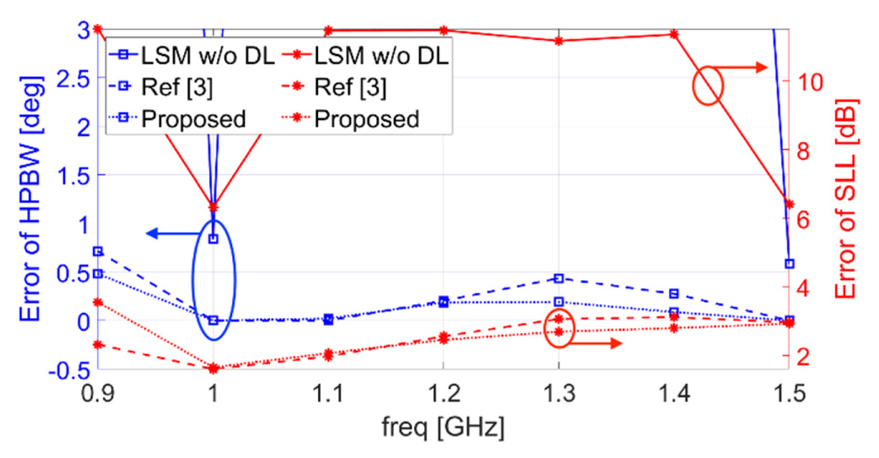
HPBW and SLL errors under a 10 dB SNR noise level
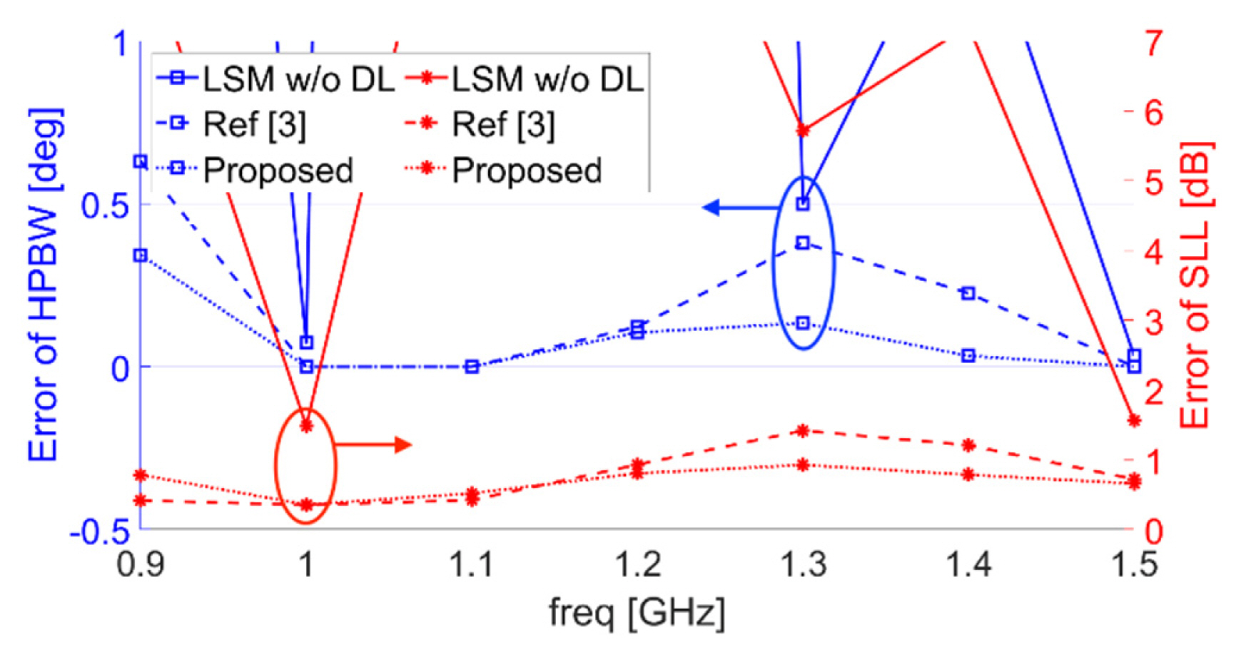
HPBW and SLL errors under 20 dB SNR noise level
V. Conclusion
The LSM limits the beamforming frequency and is vulnerable to noise, and DL has only been applied to adaptive beamforming in cases in which noise exists. For broadband beamforming, the LSM with the proposed adaptive DL should be applied before noise is added. Moreover, it is adaptive to SVs and determines when to use DL by setting α to the means of small SVs and to 0 if λM/λ1 is larger than 10–12. The results showed that it outperforms the previous methods under noise levels and expands the beamforming frequency band. We expect that the proposed method can be used to form frequency-invariant beam patterns used in monopulse algorithms to detect signals of unknown frequencies.
Acknowledgements
This work was supported by the Agency for Defense Development by the Korean government (UD200042ED).