Multiparametric Design of an All-Metal, Broadband, Slant Dual-Polarized Vivaldi Array Antenna
Article information
Abstract
An all-metal, broadband, dual-polarized Vivaldi array antenna was designed and fabricated. The structure of the proposed antenna comprised a resonant cavity and tapered fins that contacted the ground plane directly, allowing the connection of a balun and tapered fins and reducing the antenna length. To extend the frequency range, the resonant cavity width is larger than half the aperture length, and the tapered fins have nonuniform thickness. The proposed Vivaldi array antenna is designed based on parametric studies. The gains of the active element and array ranged from −2.9 dBi to 6.4 dBi and 14.9 to 23.5 dBi in the frequency range of 2–6 GHz. The proposed array antenna exhibited beam steering capability up to 45° along the azimuth and 25° along the elevation angle directions. Since the measured results and simulated predictions were in good agreement, the proposed array antenna would be applicable for a broadband, wide-beam steering system with different polarization requirements.
I. Introduction
Most recent communication systems and radar applications are required to be capable of rapidly altering beam directions and deploying their radiation pattern by changing the magnitudes and phases of the excited radiators’ signals. Such capabilities are useful in many applications for GHz–mmWave frequencies, including imaging systems and military usage [1–3]. A broadband antenna improves the resolution and selective feature detection in radar imaging systems and reduces the number of antennas with multifunction apertures, thereby requiring less space [4]. Dual-polarized antennas can generate linear, circular, and other polarization patterns according to the signal conditions of the antenna input port; this characteristic can reduce the polarization mismatch of the radiofrequency (RF) link [5]. Vivaldi (flare-notch, tapered-slot) antennas are known to behave well in wideband, single/dual-polarized array applications [3, 4, 6–8]. They are made of dielectric substrates that are light, inexpensive, and simple to manufacture, but the dielectric loss, assembly, although the soldering processes are complex and the structural strength is low. Conversely, all-metal Vivaldi antennas have reinforced strength, improve loss compared with the dielectric substrate, and allow the construction of baluns without soldering.
One type of all-metal Vivaldi antenna, commonly known as the body of revolution (BOR), has a simple radiator structure and a more complex structure at the feeding part. In large, dual-polarized array antenna systems, it is difficult to implement the BOR antenna [9]. Kindt and Pickles [10] introduced an all-metal Vivaldi antenna with a simple feeding structure and short straight lines implemented without the need for a bonding process.
However, the tapered fins of the Kindt model, which guide the excited RF signal to free space from the feeding part, are located above a resonant cavity, and a groove line connecting tapered fins to the resonant cavity is required, thus extending the antenna’s length. Moreover, the thickness of the tapered fins has a uniform profile. In this study, we propose a novel, all-metal Vivaldi antenna in which the resonant cavity and tapered fins are directly in contact with the ground plane to eliminate the groove line, thereby reducing its length. Moreover, the width of the resonant cavity is larger than half the aperture length, and the thickness of the tapered fins has a nonuniform profile along the wave propagation direction to expand the frequency range. The design parameters are chosen for a broadband range that exceeds 3:1 based on detailed multiparametric evaluations. The measured active voltage standing wave ratio (AVSWR) of the radiator placed near the center of the 8 × 8 slant dual-polarized array antenna is less than 1.71:1 for the broadside and 2.48:1 within the beam steering boundary in the frequency range of 2–6 GHz. The synthesized radiation pattern of the proposed array antenna can steer up to 45°/25° in terms of the azimuthal/elevation angles.
The remainder of this paper is organized as follows. Section II discusses the proposed Vivaldi antenna structure and presents the simulation results of multiparametric studies to design the antenna. Section III explains the fabrication and measurement results, and Section IV concludes the study.
II. Multiparametric Study of the Proposed Antenna
1. Proposed Antenna Structure
Most all-metal Vivaldi array antennas whose designs are based on the Kindt model are composed of a feeder, a resonant cavity, tapered fins, and a groove line. The feeder is responsible for signal excitation from a 50-Ω SMA connector. The resonant cavity achieves broadband impedance matching. The tapered fins guide traveling wave propagation to free space, which results in an end-fire antenna. The groove line connects the feeder to the tapered fins [2, 4].
In this study, the geometric structure of the proposed all-metal Vivaldi antenna is depicted in Fig. 1(a). The proposed antenna contains a resonant cavity and tapered fins that directly contact to the ground plane. The groove line is eliminated, and the thickness of the tapered fins progressively decreases toward the aperture. The symbols w and wa denote the antenna array and aperture sizes, respectively. T and Ta are the thicknesses of the tapered fins at the ground and aperture planes, respectively. The inner and outer diameters of the standard SMA connector of the radiator are designated as din and dout. The rectangular resonant cavity is constructed by length hc and width wc, where the width of the resonant cavity is separated wc1 and wc2 when the width is larger than half the antenna’s aperture width w. The rectangular resonant cavity is constructed by placing the left-side tapered fin onto the one on the right side. This expands the frequency range by impedance matching. The inner conductor of the standard 50-Ω SMA connector is connected to one of the tapered fins that lies at a height hs above the ground plane and has a width ws. This enables the propagation of an RF signal through a 50-Ω SMA coaxial line vertically and directly coupled to a radiator. The hole for the inner conductor of the 50-Ω SMA is machined near the center of the contact area of the tapered fin, and a solderless contact is achieved using a fuzzy button. The tapered fin is built from the ground to the aperture using Eq. (1). The curve profile of the tapered fin, o, in Fig. 1(a) is achieved as follows [11]:
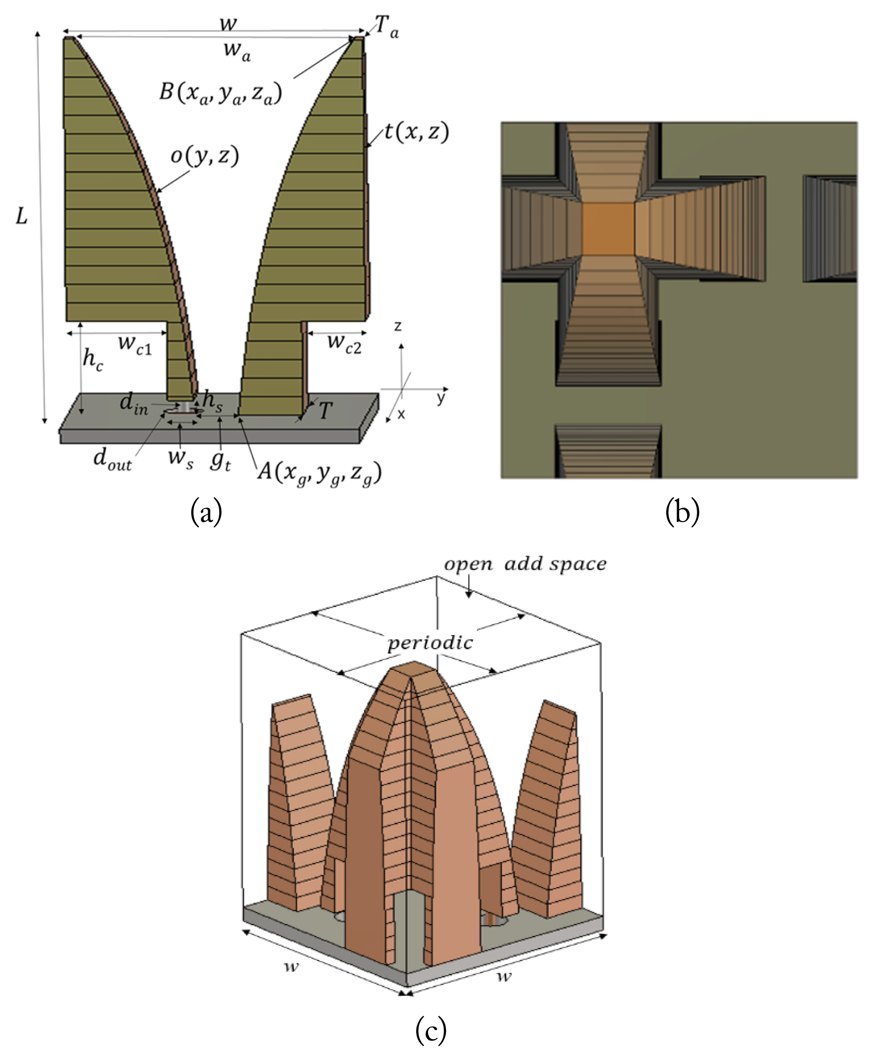
Proposed unit-cell dual-polarized antenna structure: (a) proposed antenna structure, (b) top view, and (c) isometric view with the boundary conditions of the dual-polarized unit-cell model.
where
and Ra is the change ratio of the tapered slot toward the antenna aperture. In this study, we simultaneously change the thickness of the tapered fin t in Fig. 1(a) to T at the ground and Ta at the
aperture, instead of setting it to a constant thickness [1, 2, 7, 9], as follows:
where
and Rt is the change ratio of the tapered fin thickness. The ranges of Ra and Rt are from 0 to 1. Points A and B in Fig. 1(a) are the coordinates at the ground and aperture planes of the tapered fin. Fig. 1(b) displays a top view of a dual-polarized antenna constructed by arranging the antennas in Fig. 1(a) at right angles. The boundary conditions for calculating the characteristics of the proposed dual-polarized unit-cell antenna structure as the equivalent infinite array antenna situation are shown in Fig. 1(c) by applying periodic and open add space boundary conditions. CST Microwave Studio is used to simulate the proposed antenna performance of the dual-polarized unit-cell radiator.
2. Aperture Dimensions
The array aperture dimension is defined by suppressing the grating lobe in the visible range. The triangular lattice of the array antenna is wider than the rectangular array, and the lattice distance is decided by beam steering angles and maximum operation frequency [12]. The maximum aperture dimension of the triangular lattice structure at 6 GHz, according to the maximum azimuthal and elevation angles, is shown in Fig. 2. When the maximum beam steering angles along the azimuthal and elevation directions are 45° and 25°, respectively, an aperture size less than ~28 mm is available without grating lobes in most of the visible range.

Array dimensions according to the beam steering angle.
3. Effect of Non-Uniform Thickness
The frequency range of a single antenna element in the array antenna can be determined using the active reflection coefficient (ARC), including the mutual couplings among the array antenna elements [13]. The ARC of the Vivaldi antenna yields a lower value along the longer antenna length [9]. We investigate the influence of the ARC of the uniform/non-uniform thickness profile of the tapered fin with different antenna lengths (70 mm, 90 mm) in Fig. 3. The ARC with the non-uniform profile shows better ARC performance compared with the ARC with the uniform profile at the same antenna length.
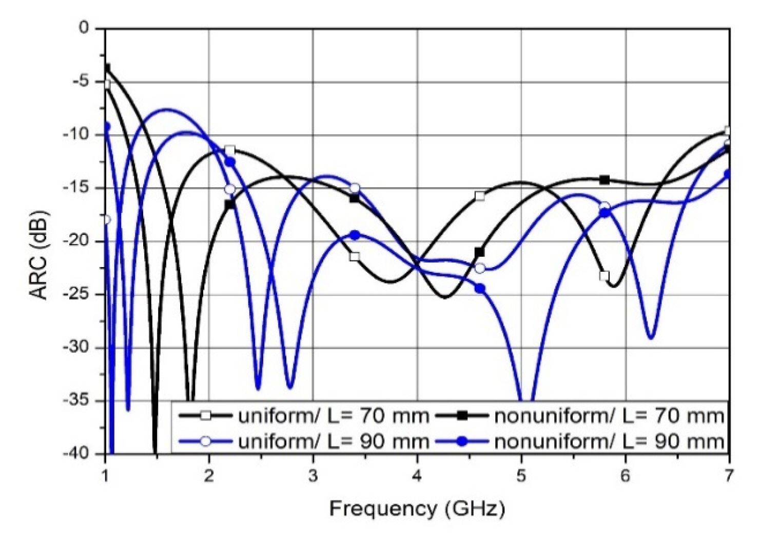
ARC as a function of frequency at different antenna lengths with uniform/non-uniform tapered fin profiles.
4. Height of the Resonant Cavity hc
The resonant cavity of the Vivaldi antenna is used for broadband impedance matching, with the RF signal entering at the center of the lateral part [1–4, 9]. In the proposed antenna, the excitation aperture from the feeding SMA connector is constructed at the edge of the resonant cavity. This proposed resonant cavity structure directly contacted the ground plane reduces the antenna length compared with previous all-metal Vivaldi antennas by using the Kindt model. We also changed the height of the rectangular resonant cavity to show the effects of the ARC. The performance of the various ARCs is shown in Fig. 4. The ARCs yielded lower values in the lower frequency range at longer heights, but shorter resonant cavity heights yielded lower ARC performance in the upper frequency band. The resonant cavity is constructed as a resonance boundary, so the ARC depends on hc.

ARC as a function of frequency at different resonant cavity heights.
5. Resonant Cavity Width wc
Most wideband phased array antennas suffer from a lower frequency band owing to their small size. As shown in Fig. 1, wc can be larger than a half of the period of w by attaching each side of the tapered fin to the neighboring radiation element. Fig. 5 shows the ARC characteristics according to the width of the resonant cavity. The wider resonant cavity has better ARC characteristics at the lower frequency range, but the ARC increases at a higher frequency.
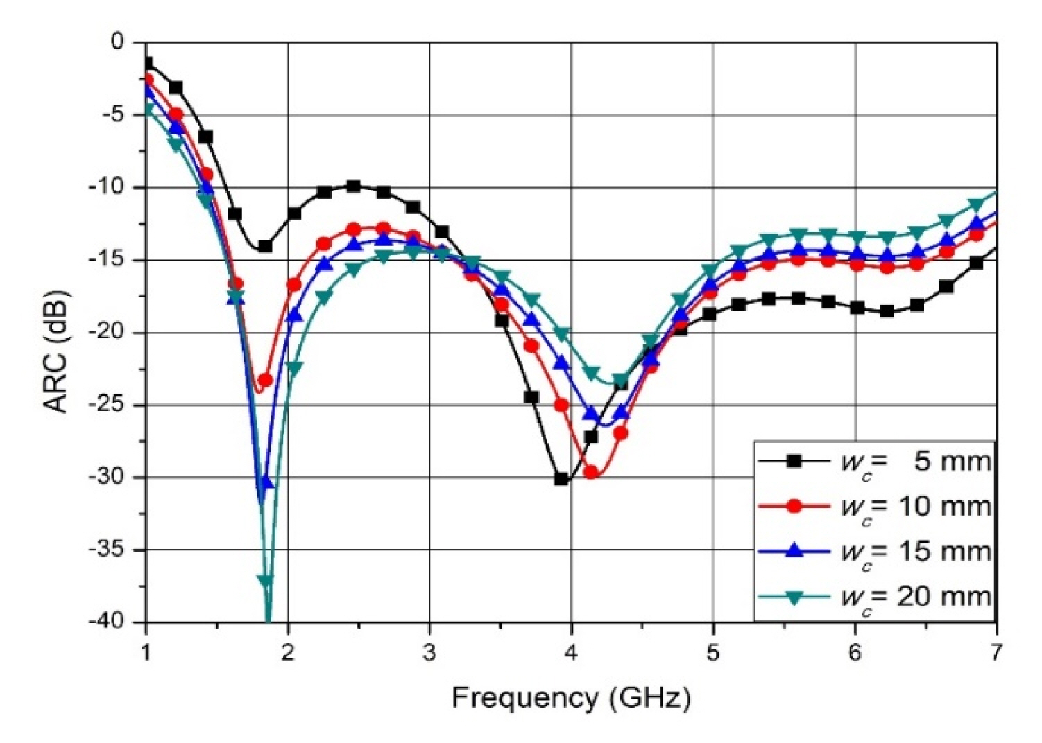
ARC as a function of frequency at different resonant cavity widths.
6. Change Ratio of Tapered Slot Ra
Ra is the ratio of changing the slot width of tapered fins from the ground to the aperture in Eqs. (1)–(3). The effect of the varying Ra on the antenna’s ARC is shown in Fig. 6. Lower values of Ra mean the shape of the tapered slot becomes a linear transition from the ground to the aperture, but larger Ra values enable the shape of the tapered slot to rapidly flare near the aperture while keeping the initial gap gt between the tapered fins from the ground to regions near the aperture. When Ra is larger than 0.5, the shape of the tapered fins is mostly similar, with long constant gaps up to the regions under the aperture from the ground plane, and the gap of the tapered fins near the antenna aperture is greatly widened. Both the similarly shaped linearly transited tapered fins and the rapidly opened tapered slot cases show worse ARC performance. This means that the guided wave is required to travel along the slowly opened tapered slot from the feeder to the aperture of the proposed antenna structure. Ra is a high-impact design parameter, since ARC is highly dependent on the change ratio of the tapered slot width [9].
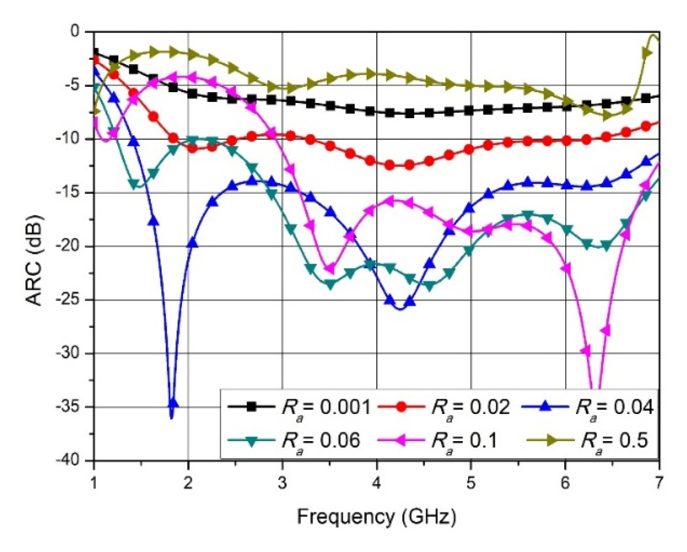
ARC as a function of frequency at different expansion ratios Ra of the tapered slot.
7. Change Ratio of Tapered Fin Thickness Rt
Rt is the ratio of the changing thickness of the tapered fins from the ground to the aperture in Eqs. (4)–(6). A lower Rt value gives the variation of thickness of the tapered fins a linear shape, but a higher value of Rt constructs a nearly constant thickness of the tapered fins up to the regions under the aperture from the ground plane, and the tapered fins’ thickness near the antenna aperture is greatly decreased. Fig. 7 shows the effect of Rt of the tapered fin’s thickness on the ARC of the antenna. The figure shows that by changing Rt from 0.001 (near linear) to 0.2, the lowest resonance frequency moves to a lower frequency, but there are similar results along Rt based on consideration of the entire frequency range.
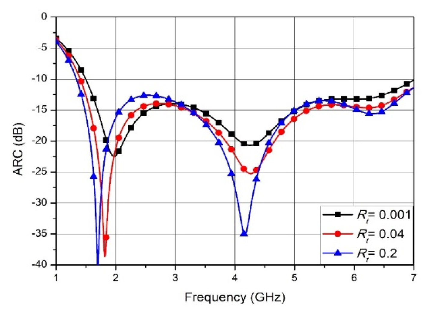
ARC as a function of frequency at different decreasing ratios Rt of the tapered fin.
8. Height of the Feed Slot hs
To vertically connect the inner conductor of the SMA connector directly to the tapered fin, the tapered fin is separated from the ground plane by removing a small box from it, as shown in Fig. 1(a). To have wideband impedance that matches with a standard coaxial connector, the height of this gap between the ground and the tapered fins is important, since it acts as a parallel plate waveguide [14]. The ARC characteristics as a function of hs are shown in Fig. 8. By increasing the height, the ARC becomes worse, since the impedance of the parallel plate waveguide becomes small.
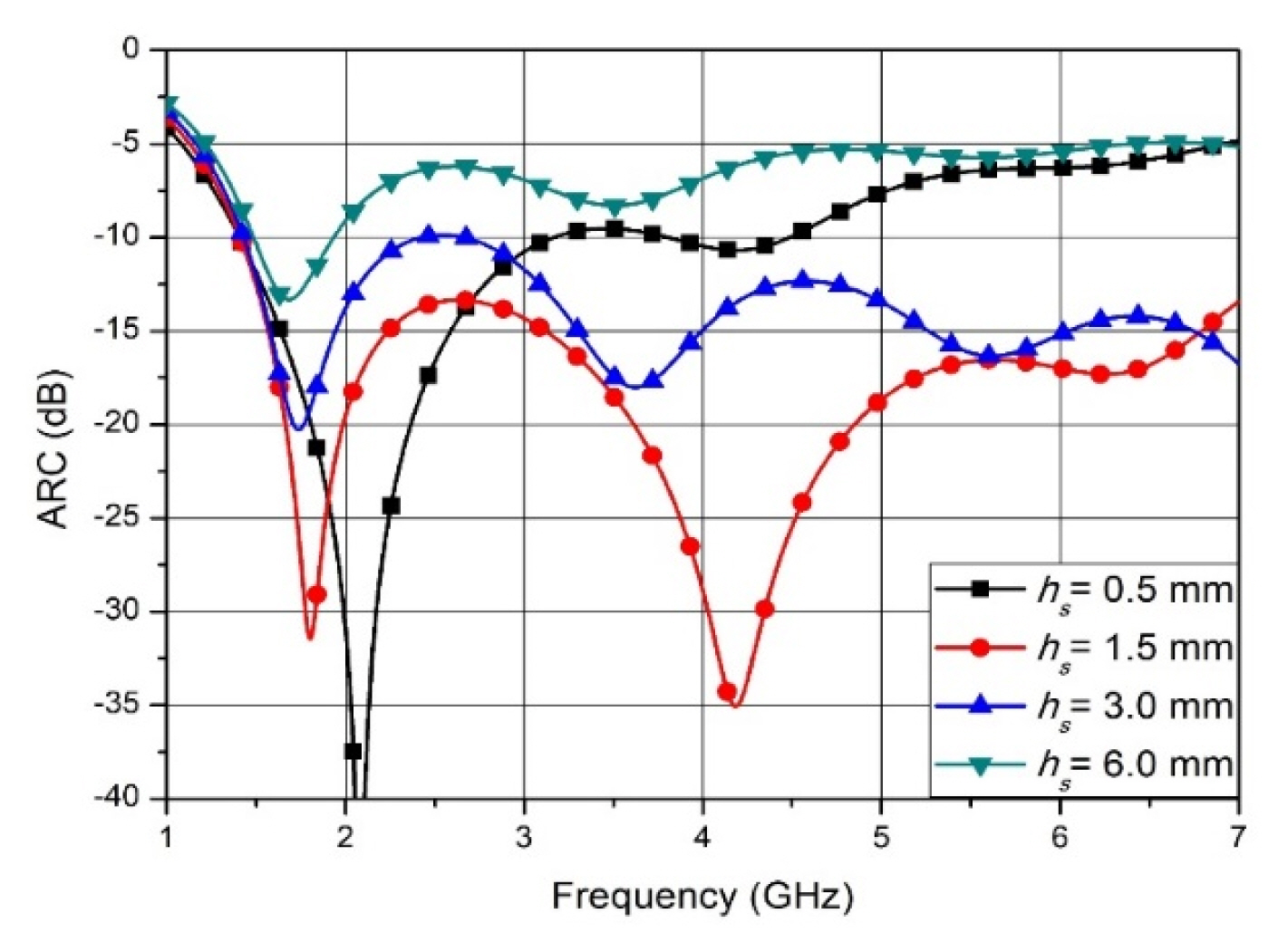
ARC as a function of frequency at different feed slot heights.
9. Width of the Feed Slot ws
The performance of the ARCs, along the width of the gap between the ground plane and the tapered fin when the SMA connector is inserted into the middle position of the contact area of the tapered fin, are shown in Fig. 9. It can be seen that as the width of the feed slot varies, the ARC curves are nearly invariable in the low-frequency band but increase at wider ws sizes. This effect of the ARC with respect to ws is less sensitive than hs, based on a comparison with the outcomes in Fig. 8.
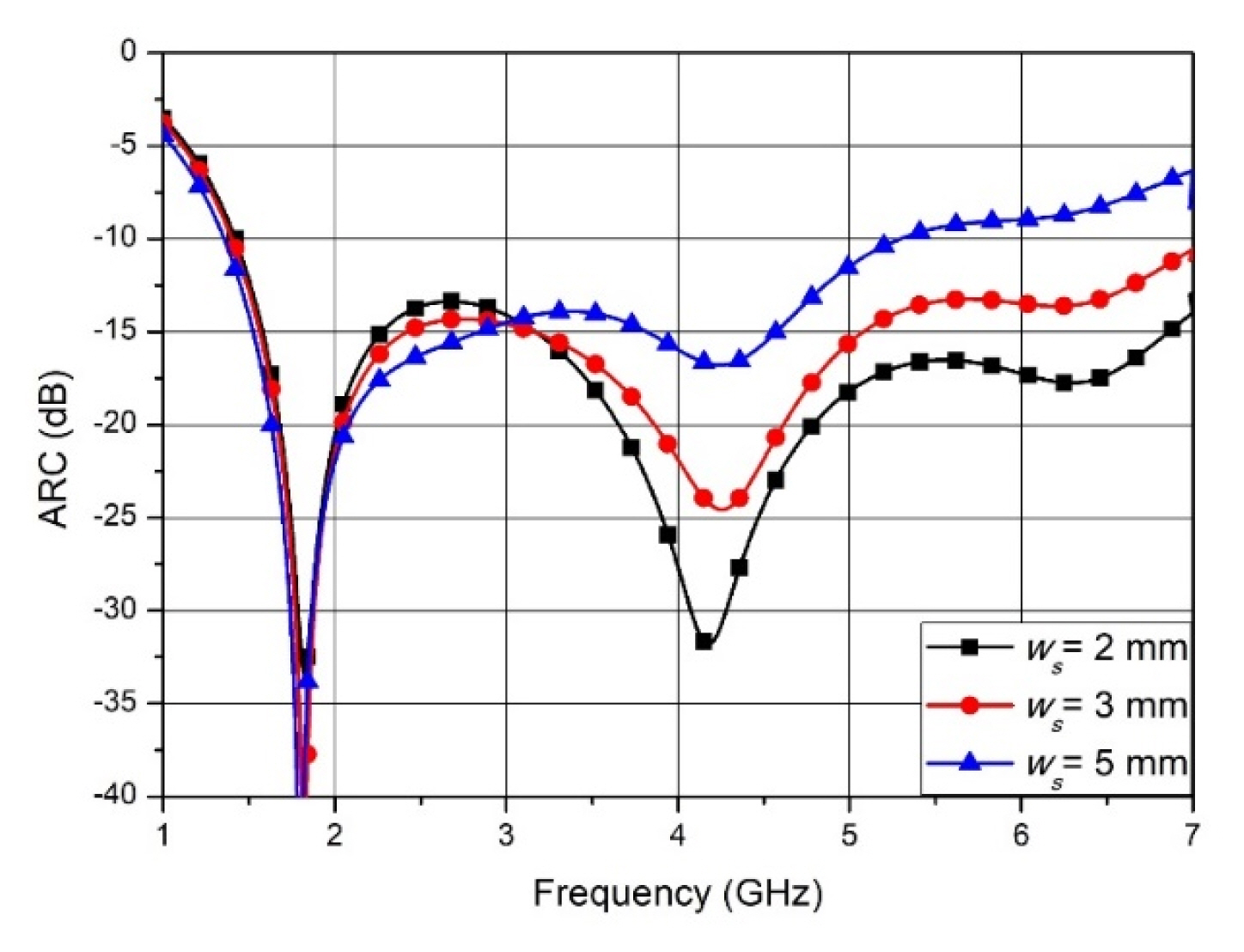
ARC as a function of frequency at different widths of the feed slot.
10. Initial Gap between the Tapered Fins gt
This section presents the effects of the variation of the initial gap between the tapered fins gt on the ARC. Fig. 10 shows the simulation results for various gap values when other parameters are invariable. It can be seen that gt has a greater effect on the reflection coefficient in most of the frequency ranges owing to the height of slot hs, and the ARC represents a better reflection performance at a specific parameter value compared with the other design parameters.
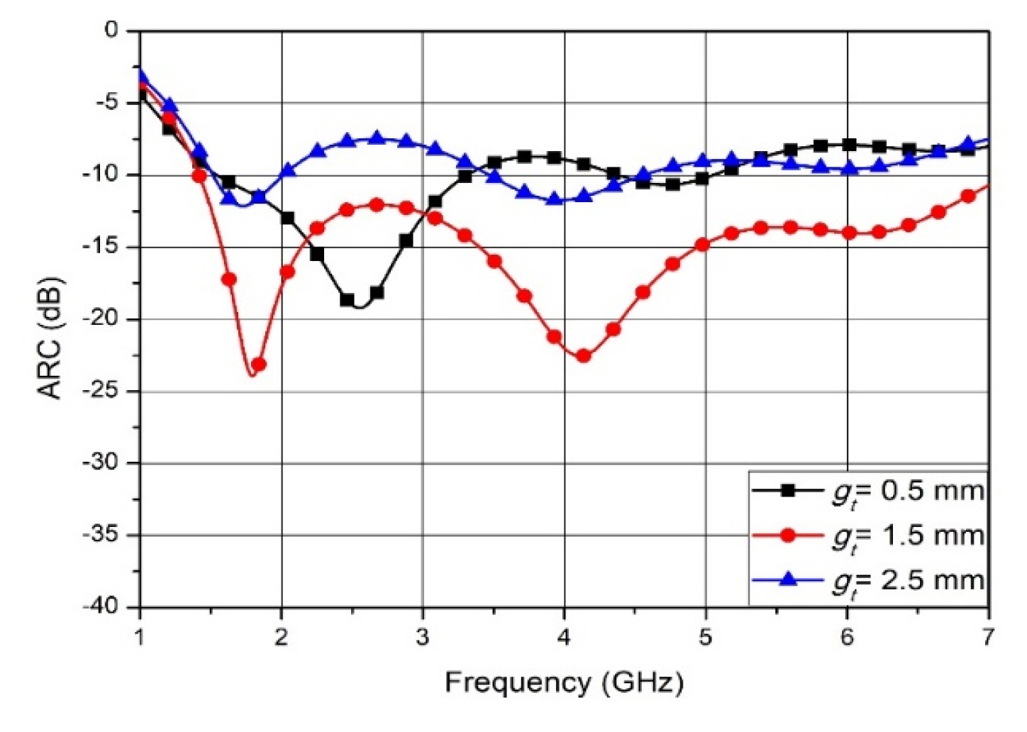
ARC as a function of frequency for different tapered fin initial gaps.
III. Fabrication and Measurement
In Section II, the ARCs are investigated while the design parameters of a proposed slant dual-polarized unit-cell Vivaldi antenna in Fig. 1 are varied. The geometric parameters of the proposed antenna are shown in Table 1.

Proposed antenna parameters
A fabricated 8 × 8 dual-polarized array antenna is shown in Fig. 11. The dual-polarized unit radiation part in Fig. 11(a) is manufactured by a milling machine based on the design parameters listed in Table 1. The proposed array antenna is assembled (consisting of the radiator, coaxial connector, and ground plane) using bolts without any soldering, as shown in Fig. 11(b). Accordingly, the defected antenna elements can be exchanged from the array by a modularized dual-polarized antenna. The assembled 8 × 8 slant dual-polarized array antenna is represented in Fig. 11(c) with a size of 385 mm × 200 mm × 72 mm (width × height × depth). To observe the ARC of the fabricated array antenna, the 64 × 64 scattering parameters (S-parameters) matrix of the + 45° slant polarized radiators were measured using a vector network analyzer (N5244A; Agilent Technologies, Santa Clara, CA, USA) in an electromagnetic anechoic chamber. The ARC of the mth port was calculated from simulations and measurements of the S-parameters with the beam-scanning angle in the azimuthal and elevation directions for the triangular array configuration. Fig. 12 shows the AVSWR results of the beam steering angles (Az, El) = (45°, 25°), (0°, 0°), and (−45°, −25°) for Port 1 (the upper-left edge element) and Port 28 (the element near the center). The measured AVSWRs of the edge port along the aforementioned beam directions from 2 GHz to 6 GHz were 2.52:1, 1.87:1, and 2.95:1. In the center port case, the proposed array antenna yielded outcomes of 2.34:1, 1.71:1, and 2.48:1, respectively. At the outer beam steering angle of the radiators placed at the edge and the center, the AVSWR increased at approximately 6 GHz. This was because the designed aperture length was slightly larger than the array distance shown in Fig. 2 at the corresponding beam steering angles, but it increased the antenna gain. The antenna located at the center of the array antenna showed better AVSWR performance than did the antenna placed at the edge, due to the symmetrical mutual coupling amount, and most measured results were in agreement with the simulated ones. The green line in Fig. 12 refers to the input VSWR excluding mutual coupling between the antennas.
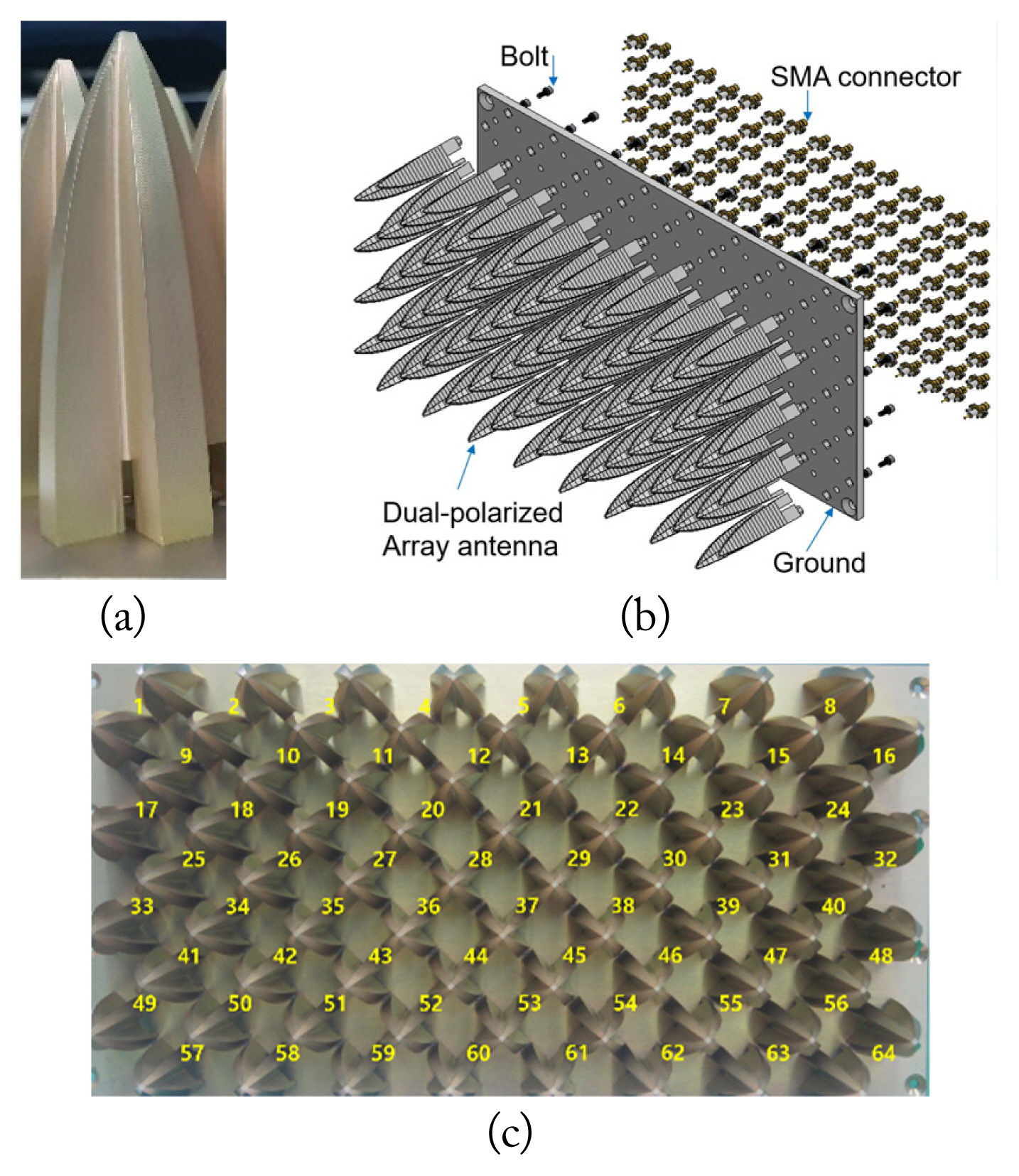
Photographs and schematic of fabricated array antenna: (a) radiator components of the flare part intended for fabrication, (b) assembly fabrication process, and (c) front view.
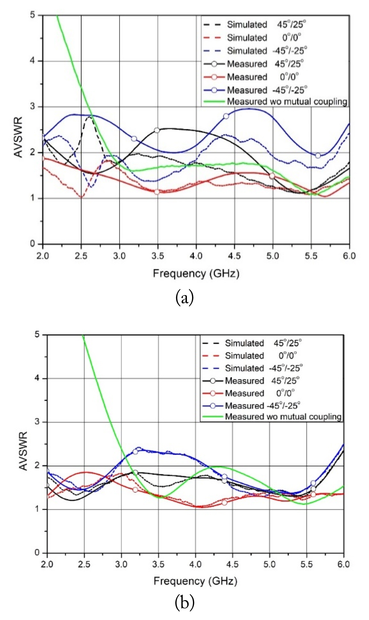
Simulations and measurements of AVSWR of the proposed array antenna: (a) Port 1 (the edge placed element) and (b) Port 28 (center placed element).
The active element patterns (AEP) were measured with only one radiator active status, and the other antenna terminated with 50-Ω loads. All ports of the proposed array were measured using a far-field antenna pattern measurement system in an anechoic chamber, and the synthesized array radiation patterns were obtained. The active element and array gains were calculated using the AEPs of all ports based on the following equations [15], with the same excited amplitude and phase at each antenna:
where ηo is an intrinsic wave impedance in the free space,
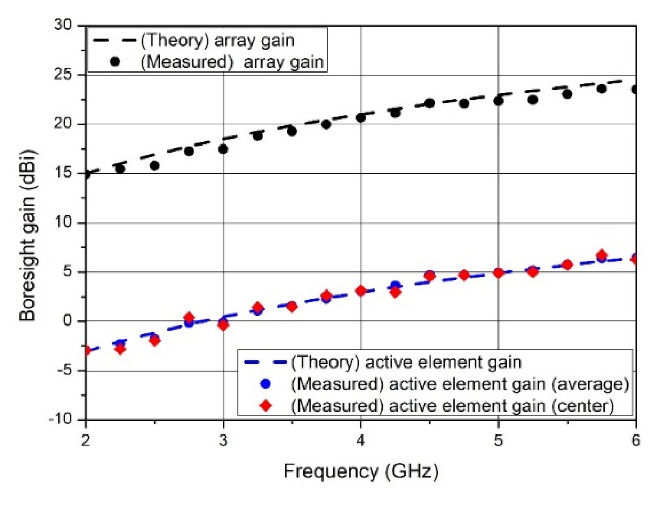
Comparison simulation and measurement of the active element gain and array gain at the boresight of the proposed array antenna with theoretical results.
Fig. 14 shows the synthesized beam steering patterns in the U- and V-domains of the proposed array antenna according to the steering of the azimuthal (Az = 45°) and elevation (El = 25°) angles at 6 GHz. The U- and V-domains are the direction cosines of the azimuth and the elevation angle of the azimuth-over-elevation coordinate [16]. The synthesized array pattern uses the theoretical excitation coefficient for each input port and applies them to the simulated and measured active element patterns. The steered beam patterns can maintain a good beam direction without the existence of the grating lobes within the beam steering angle range, which is shown by the black dotted line. The maximized beam direction of the measured result steered downward along the V-domain is attributed to a mechanical misalignment between the transmission antenna, the proposed array antenna, and an electrical reflection imperfection in the anechoic chamber for measuring active element radiation patterns using the far-field measurement system. The results demonstrate that the proposed array antenna is feasible for wide scan angle performance.
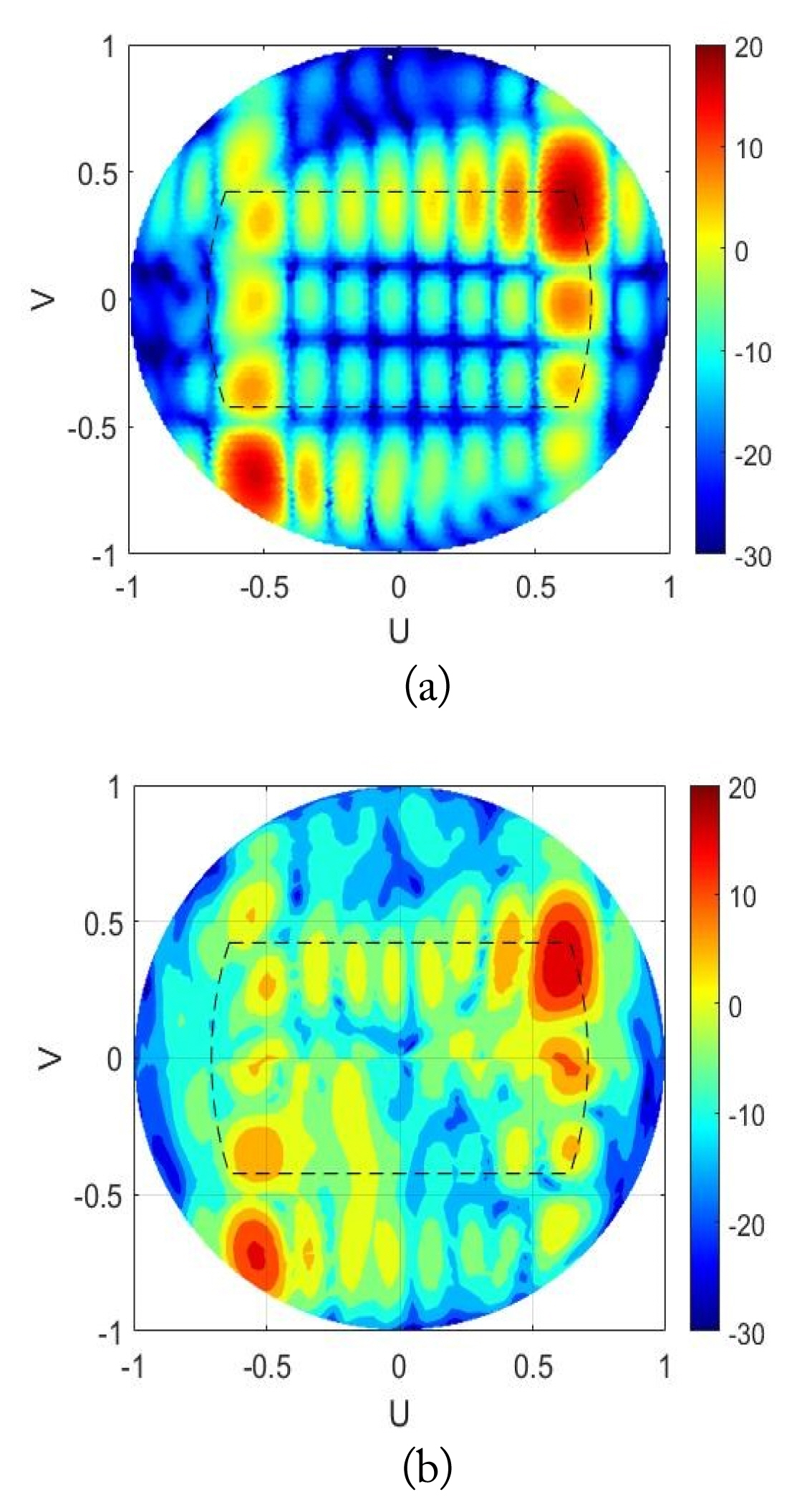
Measured and simulated array radiation patterns according to beam steering angles (Az = 45°, El = 25°) at 6 GHz: (a) simulations and (b) measurements.
Fig. 15 shows the measured active element patterns of the center-placed element of the E- and H-planes at five frequencies. All patterns are normalized to the co-polarization radiation intensity at each plane. The green line shows the normalized radiation pattern of the single antenna. At 2 GHz, the copolarized radiation patterns of the E- and H-planes are shown at approximately 100° as a −3 dB beam width. The cross-polarization ratios (CPRs) of the E- and H-planes are ≥ −20 dB within a ± 90° range from the boresight. At 3 GHz, the −3 dB beam width of the co-polarization patterns in the E- and H-planes yield values equal to 117° and 114°. Small fluctuations are shown around the boresight regions. More than −15 dB of CPR is demonstrated in the E-plane at an approximate scan angle range spanning 135°. However, the CPR of the H-plane is demonstrated to be larger than −15 dB at all scan angles, except from the 20°–45° region. At 4 GHz, the −3 dB beam width of the co-polarization patterns in the E- and H-planes yields values are equal to 105° and 90°. All patterns have reasonable flat responses around the boresight regions with small fluctuations. In the E- and H-planes, more than −15 dB of cross-polarization rejection is demonstrated at an approximate scan angle range spanning 135°. At 5 GHz, the −3 dB beam width of the co-polarization patterns in the E- and H-planes yields values equal to 108° and 114°. In the E- and H-planes, more than −15 dB of CPR is demonstrated at the 180° scan angle region. At 6 GHz, the co-polarization radiation patterns of the E- and H-plane have similar radiation shapes at 4 GHz. The −3 dB beam widths of the co-polarization patterns of the E- and H-planes are 75° and 87°, respectively. The CPR is greater than −15 dB in the E- and H-planes along the observation angle direction. All the co-polarization patterns of all the E- and H-planes exhibit no indication of scan blindness, and the CPR is greater than −15 dB at all the scan angles.
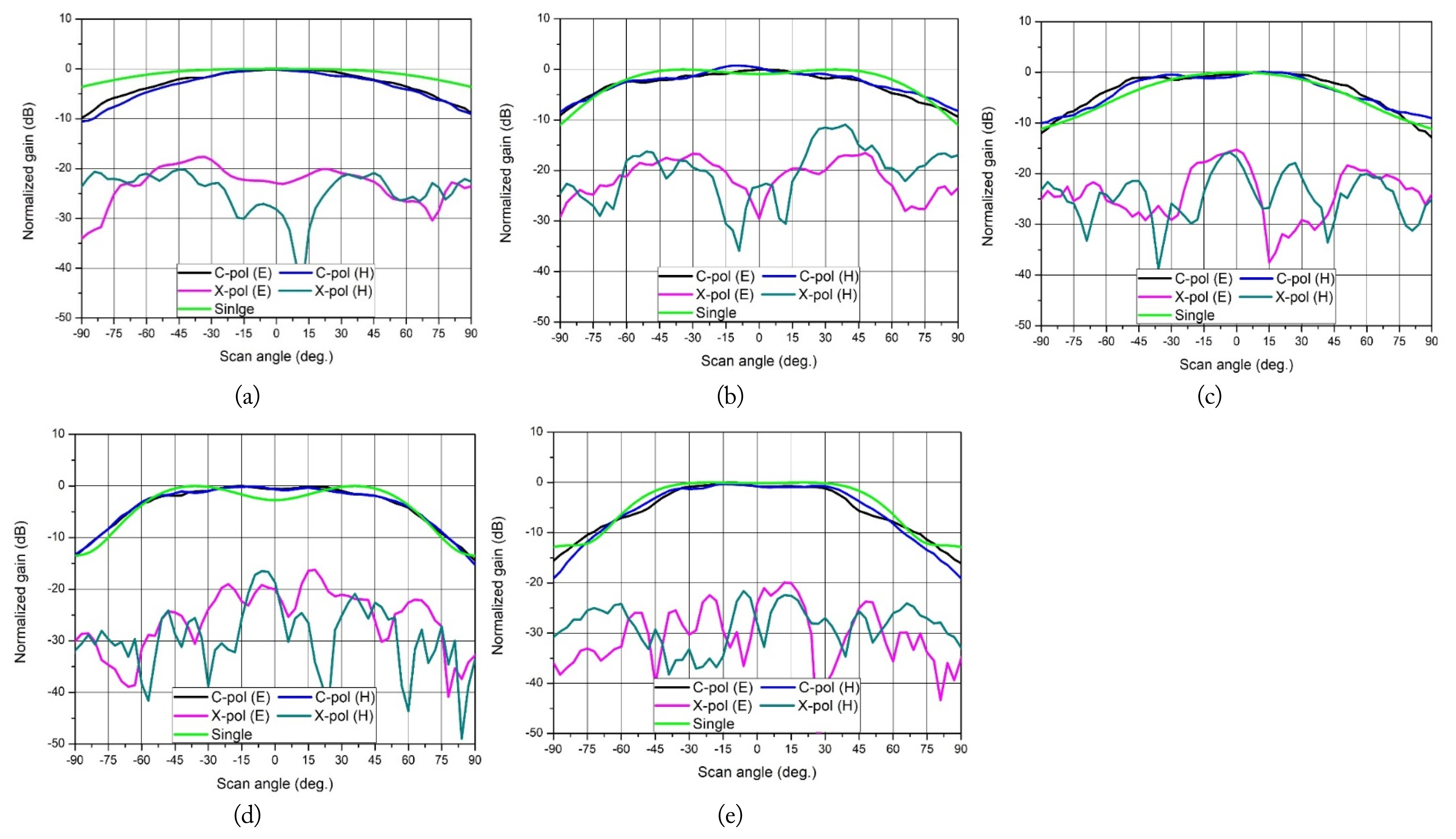
Measured cross-polarization ratio of the E- and H-planes of the center placed antenna at five frequencies: (a) 2 GHz, (b) 3 GHz, (c) 4 GHz, (d) 5 GHz, and (e) 6 GHz.
The proposed antenna has a CPR that is larger than −10 dB up to the beam steering angle of 45° along the E- and H-planes. A comparison of the all-metal wideband antennas in this paper is shown in Table 2. The element gain shows at the boresight. The feed structure is described whether the resonant cavity and tapered fins are directly contacted with or separated from the ground plane.
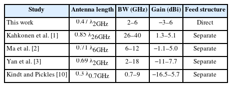
Comparison of the Vivaldi antennas
IV. Conclusion
In this study, a slant, dual-polarized, fully metallic broadband Vivaldi array antenna with a steering beam up to 45° along the azimuthal direction and a beam up to 25° along the elevation direction was designed and characterized within the frequency range of 2–6 GHz. To achieve a broadband frequency with a low CPR and low-profile characteristics, a novel antenna structure was proposed in which the thickness of the tapered fins had a nonuniform profile and directly faced the ground plane. In the proposed antenna structure, the width of the cavity was larger than half of the aperture size, and the resonant cavity was constructed directly on the ground plane. A pair of orthogonal antennas were configured as a dual-polarized unit-cell, and periodic boundary conditions were applied to impose an infinite array environment. We performed multiparametric studies to choose the antenna structure using a commercial electromagnetic solver. An 8 × 8 all-metal, slant, dual-polarized array antenna with a triangular lattice was fabricated. The measured AVSWRs at the center element in the array in the range of 2–6 GHz were 1.71:1 and 2.48:1 for the boresight and outer beam steering angles, respectively. The gains of the active elements and overall array were in the range of −2.9–6.4 dBi along the normal direction of the array’s antenna plane in the operation frequency range and yielded the maximum performance, compared with the theoretical results. The synthesized beam directions of the proposed array antenna can increase up to 45° in the azimuth and up to 25° along the elevation axis without a grating lobe within the operation beam scan angle range. The CPR level is larger than −15 dB in all scan angles in the E- and H-planes. The measured results are in very good agreement with the simulated predictions, and the proposed array antenna is expected to be applicable in broadband, wide-beam steering systems with various polarization requirements. Moreover, by fabricating the modular structures and using a metal material, the advances of the proposed array antenna will lead to easier fabrication and assembly, smaller electrical losses, and structurally robust applications.
Acknowledgments
This work was supported by the Agency for Defense Development Grant funded by the Korean Government (No. 912758101).
References
Biography

Cheol-Soo Lee received his B.S. and M.S degrees in Electronic Engineering from Ajou University, Suwon, Korea, in 1990 and 1992, respectively, and his Ph.D. degree in Radio Science and Engineering from Chungnam National University, Daejeon, Korea, in 2016. Since 1992, he has been a Chief Principal Researcher at the Agency for Defense Development, Daejeon, Korea. From 2013 to 2014, he was with the Department of Electrical and Computer Engineering, Air Force Academy, Colorado Springs, Colorado, USA, as a visiting scientist. His research interests include the design of wideband high-power transmitters and broadband phased array antennas as well as modeling and simulations of electronic warfare systems.

Joo-Rae Park received his B.S. and M.S degrees in Electronic Engineering from Chungnam National University, Daejeon, Korea, in 1991 and 1992, respectively, and his Ph.D. degree in Radio Science and Engineering from Chungnam National University, Daejeon, Korea in 2015. Since 1993, he has been a Chief Principal Researcher at the Agency for Defense Development, Daejeon, Korea. His research interests include the design of wideband high-power transmitters and broadband wide-angle beamforming devices as well as modeling and simulations of electronic warfare systems.