J. Electromagn. Eng. Sci Search

CLOSE


J. Electromagn. Eng. Sci > Volume 23(2); 2023 > Article
Choi, Park, Lee, and Jung: UHF-Printed Monopole Filtenna for Partial Discharge Detection with LTE Signal Suppression

Abstract

External partial discharge (PD) sensors for the ultra-high frequency (UHF) method are widely used to detect the PD signals in high-voltage power equipment for ease of installation and maintenance. However, conventional external PD sensors detect not only PD signals but also LTE signals; thus, a microwave filter is usually employed. In this work, a UHF filtering antenna (filtenna) is proposed as the external PD sensor to detect PD signals and simultaneously block LTE-band signals. The proposed UHF filtenna is the printed monopole antenna with a built-in interdigital bandpass geometry, which is selected for its compact size. Measurement results show that the proposed UHF-printed monopole filtenna operates adequately in the frequency range of 1 GHz to 1.6 GHz and simultaneously blocks LTE signals significantly.

I. Introduction

Partial discharge (PD) sensors for the ultra-high frequency (UHF) method are widely used to detect PD signals in high-voltage power equipment, such as power transformers, gas-insulated switchgears, and power cables [13]. PD sensors are generally classified as internal or external sensors, depending on the installation location. The internal sensor has the advantages of anti-disturbance and high sensitivity [4]. However, its installation is challenging because it should be installed at the first design stage of the high-voltage power equipment [5]. Furthermore, the maintenance of the internal sensor is impossible in high-voltage power equipment in operation [6]. On the other hand, the external PD sensor is easy to install and maintain [2]. External PD sensors have some requirements. First, the external sensor requires a compact size for the on-site installation [79]. Second, the external sensor requires the microwave filter to block LTE signals (0.829–0.959 GHz, 1.715–1.860 GHz, and 1.920–2.670 GHz in South Korea) [10]. Note that the spectrum of LTE signals overlaps with the PD signal counterpart, and its magnitude cannot be negligible. Recently, the filtenna, an antenna with a filtering characteristic, was proposed for good matching performance and miniaturization [11]. The filtenna can reduce the impedance mismatch because a filtering structure can be designed based on the input impedance of an antenna, not the characteristic impedance (50 Ω). In addition, the filtenna can miniaturize the overall microwave system since no external filters are used [1219].
In this work, we propose a UHF filtenna to detect PD signals and simultaneously block LTE signals. The proposed UHF filtenna is highly suitable for the external PD sensor since it can miniaturize the PD detection system thanks to no use of external filters. In consideration of the PD and LTE band spectrum, the target operating frequency range of the UHF filtenna is set as 1–1.6 GHz [20]. The proposed UHF filtenna is based on the printed monopole antenna integrated with an interdigital bandpass geometry for its compact size. Measurement results show that the proposed UHF-printed monopole filtenna operates adequately in the frequency range of interest and simultaneously suppresses LTE signals effectively. The remainder of this paper is organized as follows: We first present the design of the printed monopole antenna and then introduce the UHF-printed monopole filtenna. Next, experimental results of the fabricated PD filtenna are presented. Finally, concluding remarks are provided.

II. Design

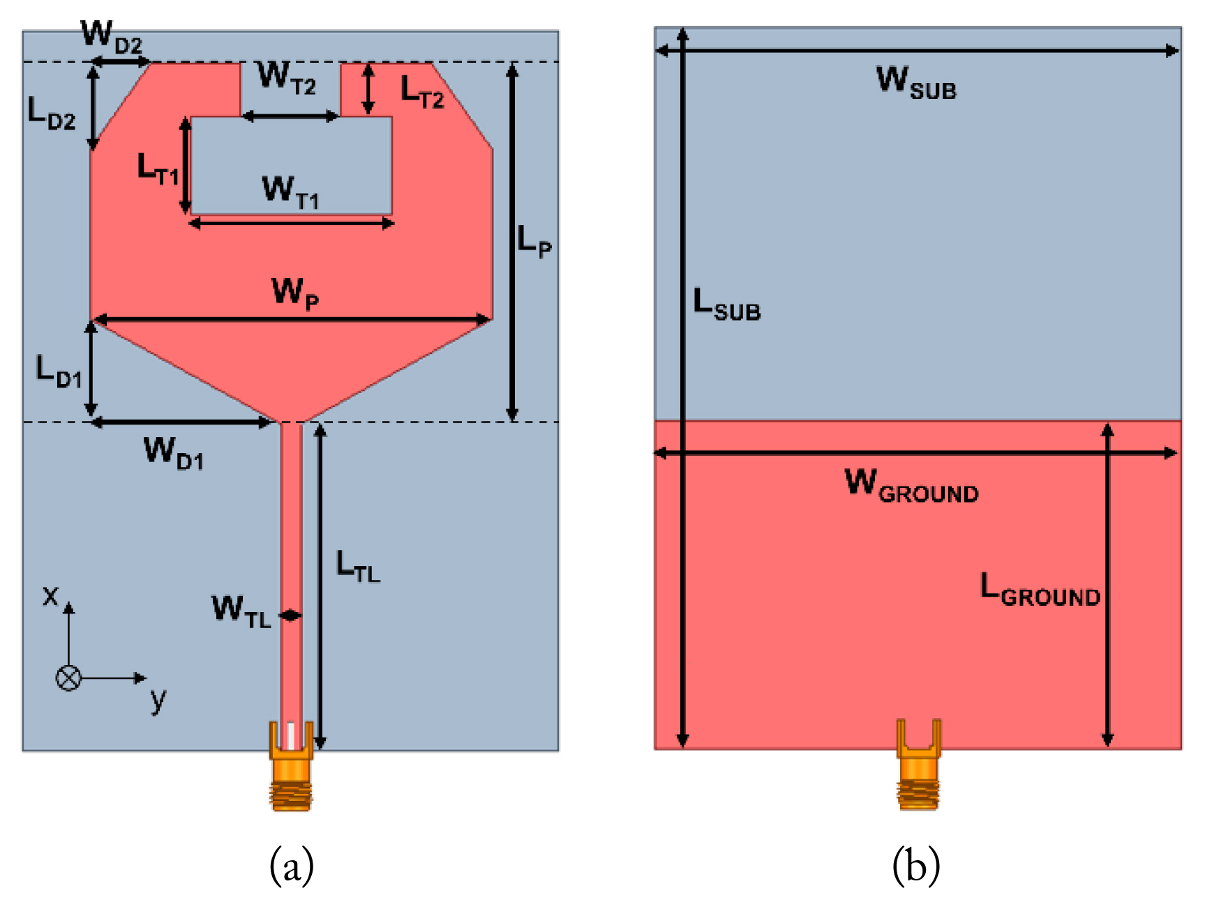
First, we present the simple antenna design considered in this work. The printed monopole antenna is designed on a 1.6 mm thick FR-4 substrate (ɛr = 4.4, tanδ = 0.02). Fig. 1 shows the schematic of the printed monopole antenna. The designed antenna is excited to a 50-Ω microstrip line through the SMA connector. The radiator of the printed monopole antenna is modified from an octagonal shape with an inverted T-shape slot at the top center [21, 22].
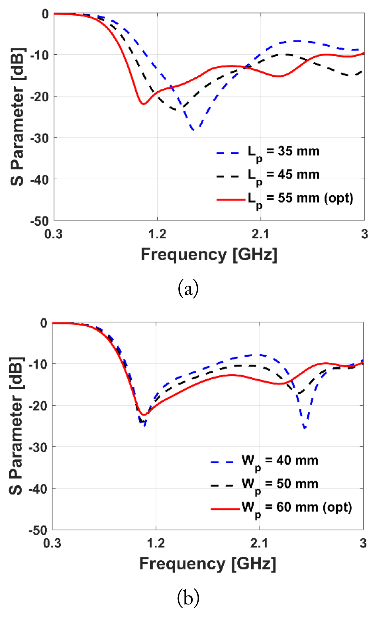
The lowest operating frequency is determined by the length of the radiator (LP) shown in Fig. 2(a). In this work, the length of the radiator (LP) is chosen as 55 mm, meaning that the lowest resonant frequency is 0.91 GHz in terms of the −10 dB reflection coefficient. Fig. 2(b) shows the simulated reflection coefficient of the printed monopole antenna with respect to the width of the radiator (WP). The width of the radiator (WP) is determined as 60 mm, which has good matching performance in the frequency range of interest. All other geometrical parameters are optimized, and the final dimensions of the printed monopole antenna designed are listed in Table 1.
Fig. 3 shows the surface current densities of the designed printed monopole antenna at 0.9 GHz, 1.3 GHz, 1.8 GHz, and 2.3 GHz. It is observed that the surface current flows well on the radiator at all frequencies. Both the reflection coefficient and the surface current density indicate that the designed, printed monopole antenna operates in not only the target frequency range but also in the LTE bands. Therefore, a filtering function structure should be integrated with the printed monopole antenna such that it works exclusively in the target operating frequency band. In this work, we realized the bandpass filtering geometry inside the printed monopole antenna for compactness. In specific, the interdigital bandpass filter is implemented in the microstrip line.
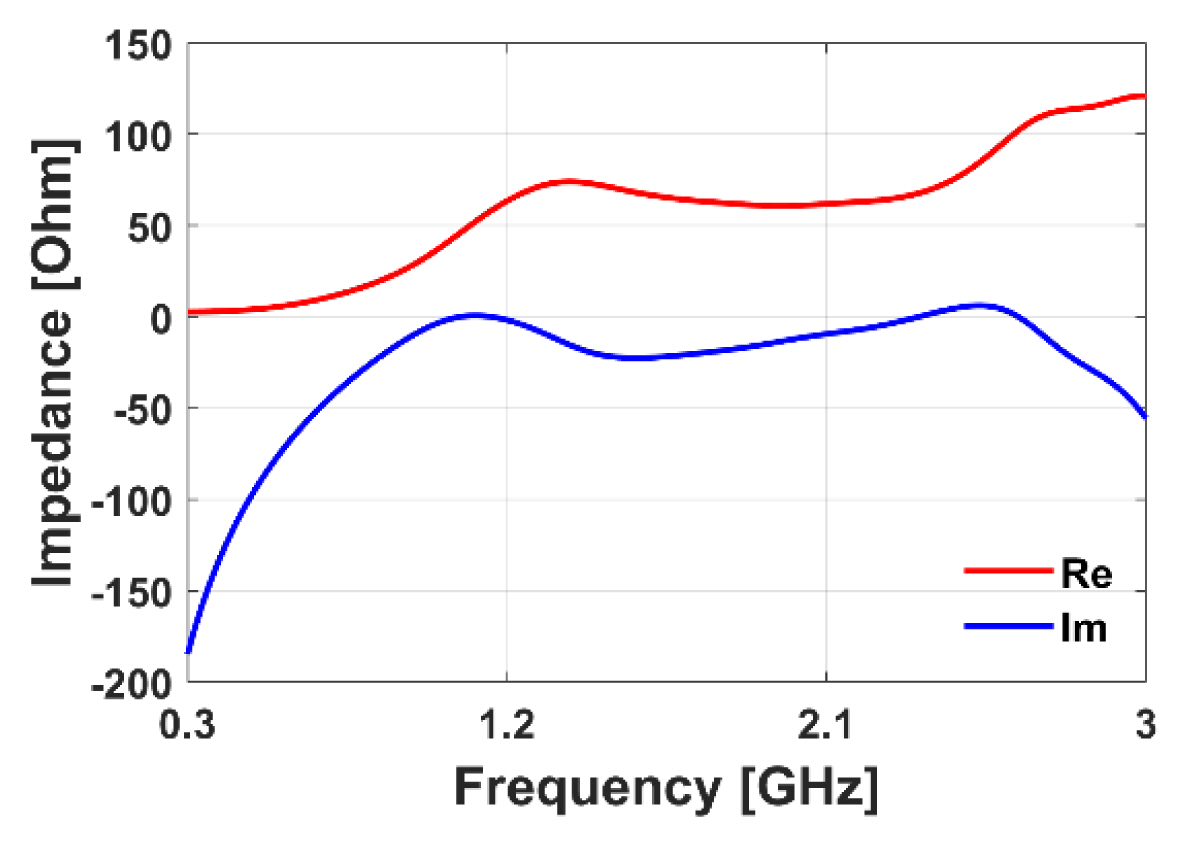
Fig. 4 shows the schematic of the interdigital bandpass filter consisting of the fifth-order resonators, which are symmetric with respect to the third resonator [23]. The via holes are located at the end of the resonators opposite to each other adjacent to the resonators such that the currents going through the adjacent resonators are out of phase. Note that the interdigital bandpass filter should be designed by considering the input impedance of the radiator, not 50 Ω. The input impedance of the radiator is obtained by the de-embedding option of the Ansys HFSS, and it changes with the frequency, as shown in Fig. 5.
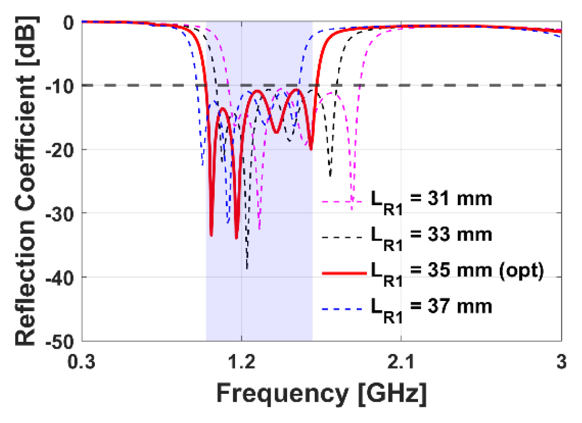
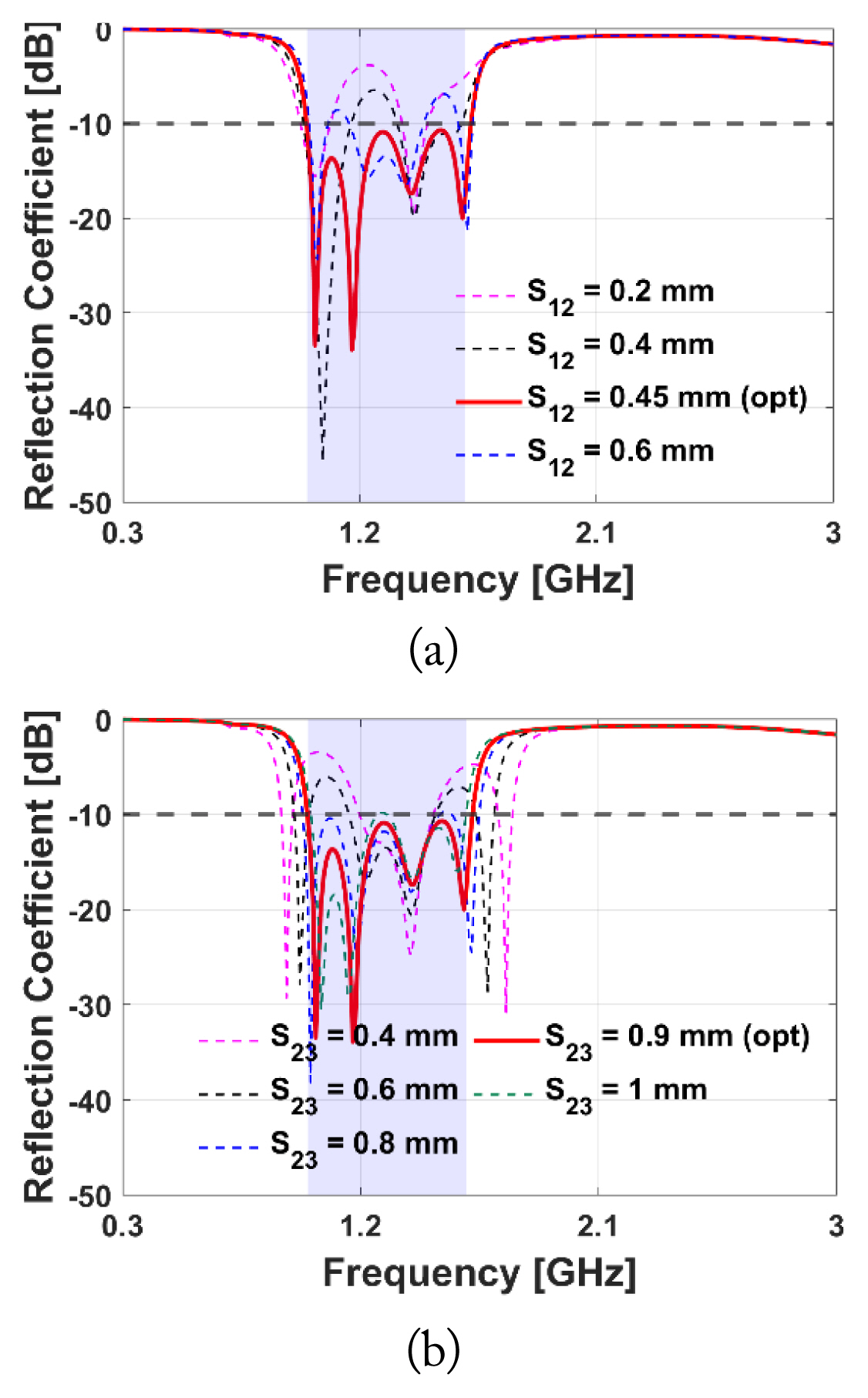
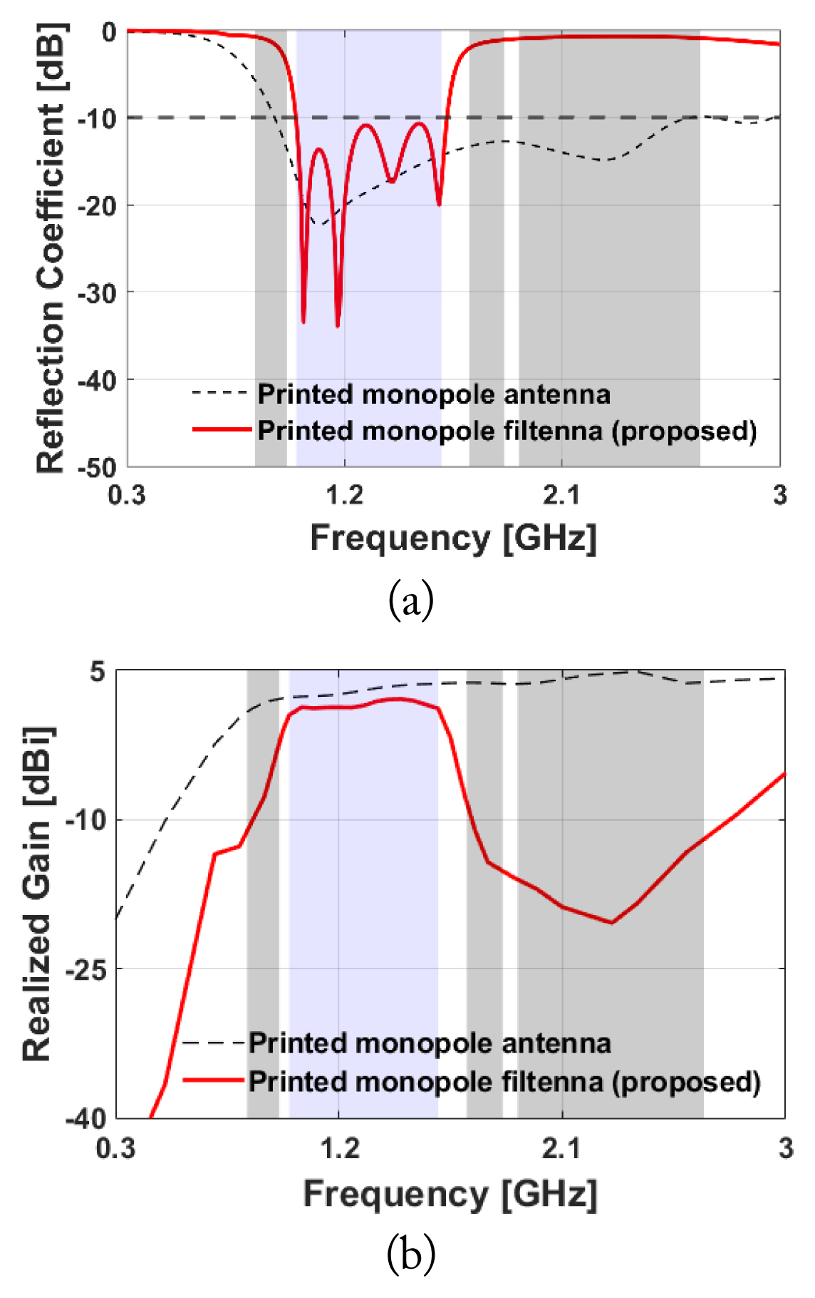
Filtering performance in the frequency range of interest is dominantly determined by the resonator length and the spacing between resonators due to the electric and magnetic couplings [2429]. First, we investigate the effect of the resonator length on filtering performance. Note that the length of each resonator should be different [27], and in this work, we set LR2 = LR1 − 3 mm, LR3 = LR1 − 4 mm. Fig. 6 shows the simulated reflection coefficient of the printed monopole filtenna versus LR1. The blue box shows the target operating frequency range of the designed UHF-printed monopole filtenna (1–1.6 GHz). As shown in Fig. 6, we obtain the following resonator length for good filtering performance: LR1 = 35 mm, LR2 = 32 mm, and LR3 = 31 mm. Next, we examine the spacing between resonators. As shown in Fig. 7, good filtering performance can be achieved for S12 = 0.45 mm and S23 = 0.9 mm. Table 2 lists the optimized dimensions of the designed interdigital bandpass filter in printed monopole filtenna. Fig. 8 illustrates the final schematic design of the proposed printed monopole filtenna. Fig. 9 compares the simulated results of the proposed printed monopole filtenna and the conventional printed monopole antenna. Here, the gray boxes indicate the LTE bands. Fig. 9(a) shows the simulated reflection coefficient, and it is clearly observed that the proposed filtenna operates in the target operating frequency range exclusively compared to the printed monopole antenna. The −10 dB S11 bandwidth of the designed filtenna is from 1 GHz to 1.62 GHz. In addition, as shown in Fig. 9(b), the realized gain of the designed printed monopole filtenna is significantly reduced in the LTE bands. The realized gain is −7.72 dBi at 0.9 GHz, −14.29 dBi at 1.8 GHz, and −20.40 dBi at 2.3 GHz. Fig. 10 shows the surface current densities of the designed UHF filtenna. It is clearly observed that the surface current does not flow into the radiator in the LTE bands due to our designed interdigital bandpass geometry.

III. Fabrication and Measurement

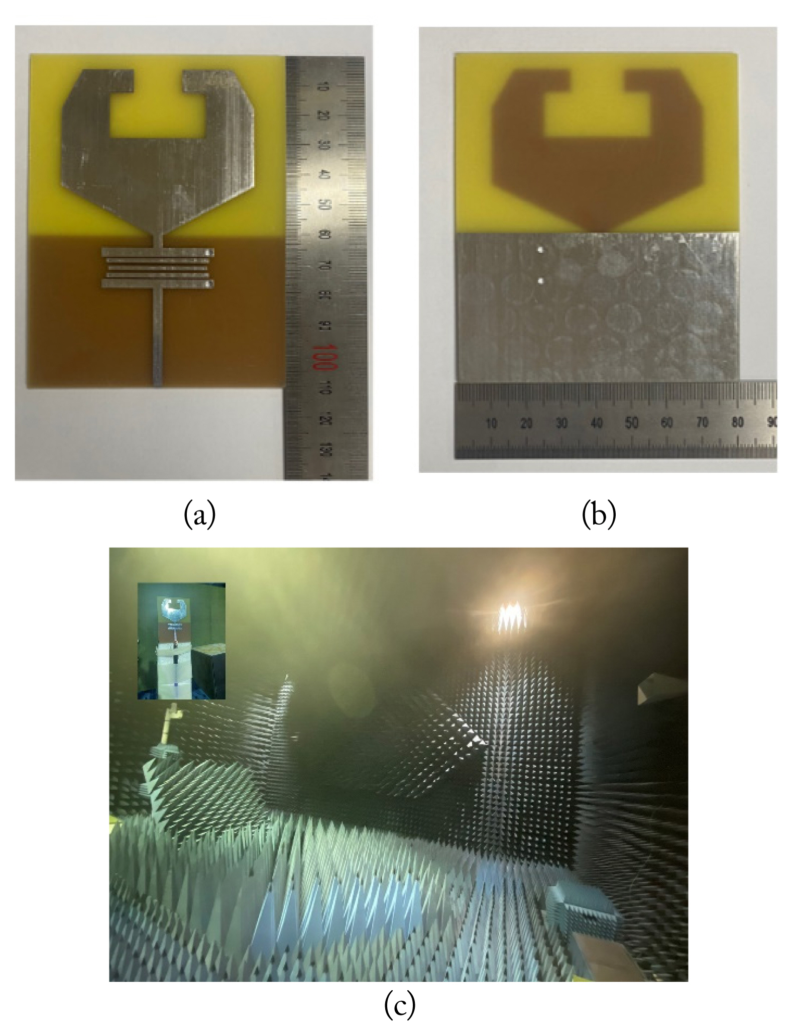
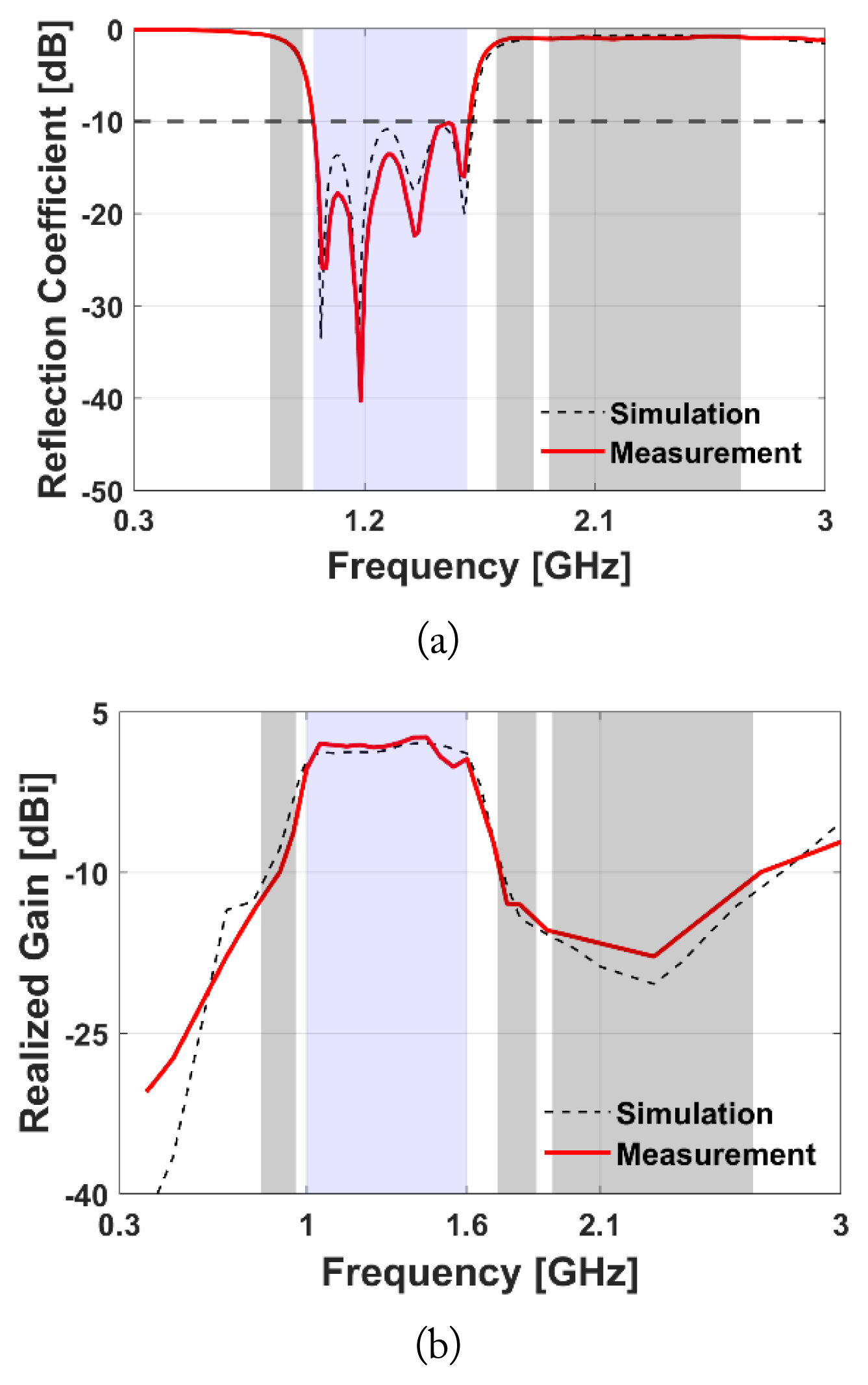
Fig. 11 displays the fabricated UHF filtenna and measurement setup. The fabricated UHF filtenna is measured in an anechoic chamber. According to Fig. 12, the measured results of the fabricated UHF filtenna generally agree with the simulated results. The discrepancies between the measured results and simulated results may be caused by fabrication and measurement errors. The measured reflection coefficient of the fabricated UHF filtenna is less than −10 dB from 1.00 GHz to 1.61 GHz. The measured peak realized gain of the UHF filtenna is −9.93 dBi at 0.9 GHz, −13 dBi at 1.8 GHz, −17.83 dBi at 2.3 GHz, and 2.64 dBi at 1.45 GHz. The fabricated UHF filtenna suppresses LTE signals effectively and operates well in the frequency range of interest simultaneously, as Fig. 12 illustrates. Fig. 13 shows the radiation pattern of the UHF filtenna at the operating frequencies. The measured radiation patterns are similar to the simulated radiation patterns. The yz-plane of the radiation patterns is illustrated in Fig. 13(a), 13(c), and 13(e). The xz-plane of the radiation patterns is illustrated in Fig. 13(b), 13(d), and 13(f). The radiation pattern of the proposed UHF filtenna is omnidirectional.

IV. Conclusion

In this work, we proposed the UHF filtenna for an external PD sensor. The proposed UHF filtenna is based on the printed monopole antenna with a built-in bandpass geometry. The proposed radiator is modified from an octagonal shape with an inverted T-shape slot, and the compact bandpass filter is realized by the interdigital geometry. The proposed UHF filtenna is fabricated and measured. The fabricated UHF filtenna can significantly block LTE signals while maintaining good antenna performance in the frequency range of interest. The reflection coefficient of the UHF filtenna is less than −10 dB in the frequency range from 1 GHz to 1.6 GHz, and the peak realized gain is −9.93 dBi at 0.9 GHz, −13 dBi at 1.8 GHz, −17.83 dBi at 2.3 GHz, and 2.64 dBi at 1.45 GHz. The radiation patterns are omnidirectional patterns in the frequency range of interest. Experimental results demonstrate that the proposed UHF-printed monopole filtenna is highly suitable for the external PD sensor.

Acknowledgments

This work was supported by the Technology Innovation Program (No. 1415178807, Development of Industrial Intelligent Technology for Manufacturing, Process, and Logistics) funded by the Ministry of Trade, Industry & Energy, Korea.

Fig. 1
Schematics of the printed monopole antenna: (a) top view and (b) bottom view.
jees-2023-2-r-158f1.jpg
Fig. 2
Simulated reflection coefficient of the printed monopole antenna with respect to the dimensions: (a) length of the radiator (LP) and (b) width of the radiator (WP).
jees-2023-2-r-158f2.jpg
Fig. 3
Surface current densities of the designed, printed monopole antenna: (a) 0.9 GHz, (b) 1.3 GHz, (c) 1.8 GHz, and (d) 2.3 GHz.
jees-2023-2-r-158f3.jpg
Fig. 4
Schematic of the interdigital bandpass geometry: (a) top view and (b) bottom view.
jees-2023-2-r-158f4.jpg
Fig. 5
Input impedance of the radiator.
jees-2023-2-r-158f5.jpg
Fig. 6
Simulated reflection coefficient of the designed, printed monopole filtenna with respect to the first resonator length (LR1).
jees-2023-2-r-158f6.jpg
Fig. 7
Simulated reflection coefficient of the designed, printed monopole filtenna with respect to the spacing between the resonators: (a) spacing between the first resonator and the second resonator (S12) and (b) spacing between the second resonator and the third resonator (S23).
jees-2023-2-r-158f7.jpg
Fig. 8
Schematic of the designed UHF-printed monopole filtenna.
jees-2023-2-r-158f8.jpg
Fig. 9
Simulated results of the designed UHF filtenna and printed monopole antenna: (a) reflection coefficient and (b) realized gain.
jees-2023-2-r-158f9.jpg
Fig. 10
Surface current densities of the filtenna: (a) 0.9 GHz, (b) 1.3 GHz, (c) 1.8 GHz, and (d) 2.3 GHz.
jees-2023-2-r-158f10.jpg
Fig. 11
Fabricated UHF filtenna and measurement setup: (a) top view, (b) bottom view, and (c) measurement setup.
jees-2023-2-r-158f11.jpg
Fig. 12
Measured results of the proposed UHF filtenna: (a) reflection coefficient and (b) realized gain.
jees-2023-2-r-158f12.jpg
Fig. 13
Radiation patterns of the proposed UHF filtenna: (a) yz-plane at 1.1 GHz, (b) xz-plane at 1.1 GHz, (c) yz-plane at 1.35 GHz, (d) xz-plane at 1.35 GHz, (e) yz-plane at 1.6 GHz, and (f) xz-plane at 1.6 GHz.
jees-2023-2-r-158f13.jpg
Table 1
Dimensions of the designed printed monopole antenna
Parameter Dimension (mm) Parameter Dimension (mm)
LP 55 WP 60
LTL 50 WTL 3
LT1 15 WT1 30
LT2 8 WT2 15
LD1 16 WD1 28.5
LD2 13 WD2 9
LSUB 110 WSUB 80
LGROUND 50 WGROUND 80
Table 2
Dimensions of the designed interdigital bandpass geometry
Parameter Dimension (mm) Parameter Dimension (mm)
LR1 35 WR1 3
LR2 32 WR2 1.6
LR3 31 WR3 1.4
LR4 32 WR4 1.6
LR5 35 WR5 3
S12 0.45 S23 0.9
S34 0.9 S45 0.45
DV1 2 DV2 0.8
DV3 0.8 DV4 0.6
DV5 2 LAF 3

References

1. J. Lee, J. Cho, J. Choi, H. Choo, and K.Y. Jung, "Design of a miniaturized spiral antenna for partial discharge detection system," Microwave and Optical Technology Letters, vol. 60, no. 1, pp. 75–78, 2018.
crossref pdf
2. C. Zhang, N. Hu, W. Yin, Y. Zhao, M. Lu, and Y. Wang, "A miniaturized planar spiral antenna for PD detection in GIS," In: Proceedings of 2020 IEEE 4th Conference on Energy Internet and Energy System Integration; Wuhan, China. 2020, pp 3302–3306.
crossref
3. Z. Cui, S. Park, H. Choo, and K.Y. Jung, "Wideband UHF antenna for partial discharge detection," Applied Sciences, vol. 10, no. 5, pp. 16982020.
crossref
4. S. Park and K.Y. Jung, "Design of a circularly-polarized UHF antenna for partial discharge detection," IEEE Access, vol. 8, pp. 81644–81650, 2020.
crossref
5. Z. Zeng, Y. Hu, and W. Zhang, "An external UHF miniaturized compound spiral slot antenna for partial discharge detection in GIS," In: Proceedings of 2020 8th International Conference on Condition Monitoring and Diagnosis; Phuket, Thailand. 2020, pp 198–201.
crossref
6. W. Sriyono, W.A. Putro, K. Nishigouchi, U. Khayam, M. Kozako, M. Hikita, K. Urano, and C. Min, "Sensitivity verification and determination of the best location of external UHF sensors for PD measurement in GIS," In: Proceedings of 2012 IEEE International Conference on Condition Monitoring and Diagnosis; Bali, Indonesia. 2012, pp 698–701.

7. T. Yang, J. Wu, G. Zhang, L. Huang, Q. Lv, L. Zhang et al., "Design of new-type external sensor for partial discharge detection in GIS," In: Proceedings of 2017 2nd International Conference on Frontiers of Sensors Technologies (ICFST); Shenzhen, China. 2017, pp 82–85.
crossref
8. Y. Wang, Z. Wang, and J. Li, "UHF Moore fractal antennas for online GIS PD detection," IEEE Antennas and Wireless Propagation Letters, vol. 16, pp. 852–855, 2017.
crossref
9. Y. Wang, J. Guan, Y. Geng, and C. Feng, "A miniaturised LS Peano fractal antenna for partial discharge detection in gas insulated switchgear," Sensors & Transducers, vol. 240, no. 1, pp. 19–25, 2020.

10. Z. Tang, C. Wang, W. Chang, C. Li, Q. Lu, and J. Qu, "A combined noise-rejection method for UHF PD detection on-site," IEEE Transactions on Dielectrics and Electrical Insulation, vol. 19, no. 3, pp. 917–924, 2012.
crossref
11. F. Queudet, I. Pele, B. Froppier, Y. Mahe, and S. Toutain, "Integration of pass-band filters in patch antennas," In: Proceedings of 2002 32nd European Microwave Conference; Milan, Italy. 2002, pp 685–688.
crossref
12. W.J. Wu, Y.Z. Yin, S.L. Zuo, Z.Y. Zhang, and J.J. Xie, "A new compact filter-antenna for modern wireless communication systems," IEEE Antennas and Wireless Propagation Letters, vol. 10, pp. 1131–1134, 2011.
crossref
13. M.C. Tang, P. Guo, D. Li, K.Z. Hu, M. Li, and R.W. Ziolkowski, "Vertically polarized, high-performance, electrically small monopole filtennas," IEEE Transactions on Antennas and Propagation, vol. 70, no. 2, pp. 1488–1493, 2022.
crossref
14. M. Li, S. Tian, M.C. Tang, and L. Zhu, "A compact low-profile hybrid-mode patch antenna with intrinsically combined self-decoupling and filtering properties," IEEE Transactions on Antennas and Propagation, vol. 70, no. 2, pp. 1511–1516, 2022.
crossref
15. C. Mao, L. Zhang, M. Khalily, Y. Gao, and P. Xiao, "A multiplexing filtering antenna," IEEE Transactions on Antennas and Propagation, vol. 69, no. 8, pp. 5066–5071, 2021.
crossref
16. Y. Zhang, X.Y. Zhang, and Y.M. Pan, "Compact single-and dual-band filtering patch antenna arrays using novel feeding scheme," IEEE Transactions on Antennas and Propagation, vol. 65, no. 8, pp. 4057–4066, 2017.
crossref
17. M.M. Hosain, S. Kumari, and A.K. Tiwary, "Novel monopole microstrip filtenna for UWB applications," Progress In Electromagnetics Research Letters, vol. 95, pp. 63–71, 2021.
crossref
18. Z.A.A. Nasser, Z. Zakaria, N.A. Shairi, S.N. Zabri, and A.M. Zobilah, "Design of compact filtenna based on capacitor loaded square ring resonator for wireless applications," Progress In Electromagnetics Research M, vol. 96, pp. 21–31, 2020.
crossref
19. A. Bembarka, L. Setti, A. Tribak, H. Nachouane, and H. Tizyi, "Frequency tunable filtenna using defected ground structure filter in the sub-6 GHz for cognitive radio applications," Progress In Electromagnetics Research C, vol. 118, pp. 213–229, 2022.
crossref
20. K.C. Ghanakota, Y.R. Yadam, S. Ramanujan, V. Prasad, and K. Arunachalam, "Study of ultra high frequency measurement techniques for online monitoring of partial discharges in high voltage systems," IEEE Sensors Journal, vol. 22, no. 8, pp. 11698–11709, 2022.
crossref
21. F. Yang, C. Peng, Q. Yang, H. Luo, I. Ullah, and Y. Yang, "An UWB printed antenna for partial discharge UHF detection in high voltage switchgears," Progress In Electromagnetics Research C, vol. 69, pp. 105–114, 2016.
crossref
22. S. Park and K.Y. Jung, "Novel compact UWB planar monopole antenna using a ribbon-shaped slot," IEEE Access, vol. 10, pp. 61951–61959, 2022.
crossref
23. J.S. Hong and M.J. Lancaster, Microstrip Filters for RF/Microwave Applications. Hoboken, NJ: Wiley, 2001.

24. A. Basit, M.I. Khattak, M. Al-Hasan, J. Nebhen, and A. Jan, "Design and analysis of a compact GSM/GPS dual-band bandpass filter using a T-shaped resonator," Journal of Electromagnetic Engineering and Science, vol. 22, no. 2, pp. 138–145, 2022.
crossref pdf
25. A. Basit, M.I. Khattak, A. Althuwayb, and J. Nebhen, "Compact tri-band bandpass filter based on asymmetric step impedance resonators for WiMAX and RFID systems," Journal of Electromagnetic Engineering and Science, vol. 21, no. 4, pp. 316–321, 2021.
crossref pdf
26. M.I. Khan, M.I. Khattak, and M. Al-Hasan, "Miniaturized MIMO Antenna with low inter-radiator transmittance and band rejection features," Journal of Electromagnetic Engineering and Science, vol. 21, no. 4, pp. 307–315, 2021.
crossref pdf
27. Y. Mu, Z. Ma, and D. Xu, "A novel compact interdigital bandpass filter using multilayer cross-coupled folded quarter-wavelength resonators," IEEE Microwave and Wireless Components Letters, vol. 15, no. 12, pp. 847–849, 2005.
crossref
28. Y. Kim, "Analysis method for a multi-section rat-race hybrid coupler using microstrip lines," Journal of Electromagnetic Engineering and Science, vol. 22, no. 2, pp. 95–102, 2022.
crossref pdf
29. S.Y. Jang and J.R. Yang, "Double split-ring resonator for dielectric constant measurement of solid and liquids," Journal of Electromagnetic Engineering and Science, vol. 22, no. 2, pp. 122–128, 2022.

Biography

jees-2023-2-r-158i1.jpg
Junmo Choi received his B.S. degree in electronic and information engineering at the Korea Aerospace University, Goyang, South Korea, in 2021. He is working toward a Ph.D. in electronic engineering from Hanyang University, Seoul, South Korea. His research interests include filtering antennas and mmWave antennas.

Biography

jees-2023-2-r-158i2.jpg
Seungyong Park received his B.S. degree in information and communication engineering from Chungbuk University, Cheongju, South Korea, in 2016. He is working toward a Ph.D. in electrical engineering from Hanyang University, Seoul, South Korea. His research interests include doppler radar for medical applications, UWB antenna for an indoor positioning system, and antenna design for next-generation wireless communication systems.

Biography

jees-2023-2-r-158i3.jpg
Jisu Lee received her B.S. degree in electronic engineering from Seokyeong University, Seoul, South Korea, in 2019. She is working toward a Ph.D. in electronic engineering at Hanyang University, Seoul, South Korea. Her research interests include antenna development.

Biography

jees-2023-2-r-158i4.jpg
Kyung-Young Jung received his B.S. and M.S. degrees in electrical engineering from Hanyang University, Seoul, South Korea, in 1996 and 1998, respectively, and his Ph.D. degree in electrical and computer engineering from Ohio State University, Columbus, USA, in 2008. From 2008 to 2009, he was a postdoctoral researcher at Ohio State University, and from 2009 to 2010, he was an assistant professor with the Department of Electrical and Computer Engineering, Ajou University, Suwon, South Korea. Since 2011, he has worked at Hanyang University, where he is now a professor in the Department of Electronic Engineering. His research interests include computational electromagnetics, bioelectromagnetics, and nanoelectromagnetics. Dr. Jung was a recipient of the Graduate Study Abroad Scholarship from the National Research Foundation of Korea, the Presidential Fellowship from Ohio State University, the HYU Distinguished Teaching Professor Award from Hanyang University, and the Outstanding Research Award from the Korean Institute of Electromagnetic Engineering and Science.
TOOLS
Share :
Facebook Twitter Linked In Google+
METRICS Graph View
  • 3 Crossref
  • 2 Scopus
  • 1,304 View
  • 77 Download
Related articles in JEES

ABOUT
ARTICLE CATEGORY

Browse all articles >

BROWSE ARTICLES
AUTHOR INFORMATION
Editorial Office
#706 Totoo Valley, 217 Saechang-ro, Yongsan-gu, Seoul 04376, Korea
Tel: +82-2-337-9666    Fax: +82-2-6390-7550    E-mail: admin-jees@kiees.or.kr                

Copyright © 2024 by The Korean Institute of Electromagnetic Engineering and Science.

Developed in M2PI

Close layer
prev next