I. Introduction
Wireless power transfer (WPT) is becoming a popular technique for diverse applications, including consumer electronic products, unmanned aerial vehicles, and implantable medical devices [1ŌĆō3]. Omnidirectional charging is critical for improving system compatibility. In [4], a coupler with multiple coils nested in each other achieves stable transmission efficiency with any angular and lateral misalignment. In [5], a crossed dipole coupler with a rotating magnetic field achieves charging at any position in the same plane. In [6], a cube dipole transmitter (Tx) is used to charge multiple receivers (Rx). In [7], a cubic Tx in an optimized structure reduces costs and achieves stable transmission efficiency. In [8], a double 3D coil Tx improves the systemŌĆÖs anti-offset ability. In [9], by adding a three-orthogonal-plane core to a Tx, the magnetic field distribution becomes uniform without increasing the Tx size or system complexity. In [10], a bowl-shaped Tx provides both spatial freedom and high efficiency, offering a promising charging solution for mobile devices. In [11], a dual-band omnidirectional 3D Tx can simultaneously offer specific advantages for the requirements of different frequencies, distances, and power. In [12], transmission performance increases with a dihedral coil angle of 80┬░ŌĆō85┬░. In [13], an original double toroidal helix-coil Tx is a high-efficiency omnidirectional coupler that maintains transmission efficiency above 90% in almost the entire range of Rx positions at a transfer distance of 200 mm. Changing the structure of the Tx can make the magnetic field more uniform, while changing the structure of the Rx also enhances the coupling coefficient. In [14], a quadrature-shaped Rx realizes an angular misalignment-insensitive omnidirectional WPT system.
Algorithm makes the Tx generate a uniform rotating magnetic field [15,16]. The position of the Rx needs to be calculated [17,18] to increase transmission efficiency [19]. In [20], a uniform magnetic field is formed by rotating the Tx. In [21], a butterfly-shaped Tx significantly improves system efficiency when Rx rotates. In [22], a cubic magnetic coupler obtains a higher coupling coefficient and has high misalignment tolerance. In [23], a spatial rotating DD coil is proposed to solve the power fluctuation problem of dynamic WPT systems at medium and long transmission distances.
When the structure of the Tx changes, the magnetic field changes accordingly. Therefore, this work explores a curved circular coil and analyzes the changes in the transmission performance of coils with curved angles ranging from 90┬░ to 180┬░. The 160┬░ and 90┬░ coils show the best transmission performance. Thus, two kinds of quasi-omnidirectional transmitters are fabricated. The 160┬░ curved-coil Tx shows good transmission performance, while the 90┬░ Tx shows stable transmission performance.
The rest of this paper is organized as follows. The equivalent circuit analysis is presented in Section II, which describes the mutual inductance variations in the curved coil region. The proposed curved coils are introduced with a design example in Section III. The experimental verification of the proposed concept is presented in Section IV. Section V presents the conclusions.
II. Theoretical Analysis
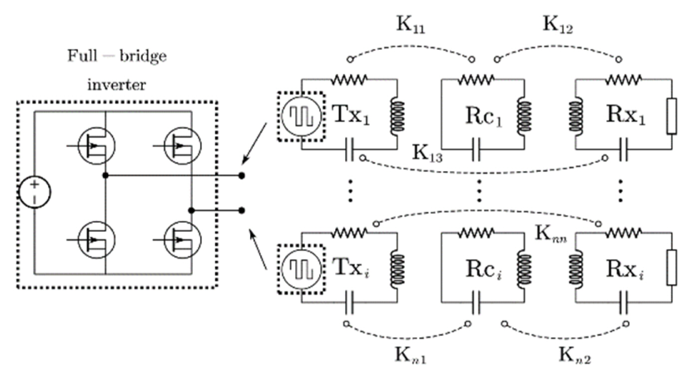
A WPT coupler is composed of Tx coils, relay coils, and Rx coils, and the number of coils can be adjusted according to different needs. By adjusting the number and shape of the coils, different electromagnetic fields can be generated. The equivalent circuit of the WPT system is shown in Fig. 1.
The Tx, relay, and Rx coils are tuned to a working frequency Žē0 using capacitors in a series. The Tx coils are connected to full-bridge converters (high-frequency sources), as illustrated in Fig. 1. The coupled mode theory model of the proposed WPT system can be expressed as in [24]:
(1)
where ai = AseŌłÆjŽēt denotes the energy modes of the transmitting and receiving circuits, Žēi denotes the coilŌĆÖs intrinsic frequency, Žäi denotes the coilŌĆÖs loss, Kij = Kji (i = j:1, 2, ŌĆ”, n) denotes the coupling coefficient between the coils, and Fi denotes the DC power supply.
By transforming Eq. (1), the power inside the Tx, relay, and Rx coils can be expressed as
(2)
Each coilŌĆÖs power is proportional to Kij and inversely proportional to the coilŌĆÖs loss and intrinsic frequency, so the resonant system reduces the loss. When the coilsŌĆÖ position change, Kij also changes, causing fluctuations in transmission performance. When the Tx coils are perpendicular, they contain only supply power and coupled power. Therefore, they should be kept nearly perpendicular to reduce coupling effects. Relay coils, which have only coupled power, can increase the transmission range. By optimizing their structure, transmission performance can increase. The Rx coils have only coupled power. Transmission performance stability is achieved when the power load is constant. When an Rx coil changes positions, Kij should remain the same to maintain a constant power load. Thus, to achieve transfer performance stability, Kij should remain constant. The coupling coefficient is expressed as
where Li denotes the coilŌĆÖs inductance, and M denotes the couplerŌĆÖs mutual inductance. Eq. (3) indicates that transmission performance is stable when M is constant. M is related to the couplerŌĆÖs physical structure and spatial position. The coils are coupled. To reduce the calculations and analysis, we introduce magnetic induction as
where I denotes the coilŌĆÖs current, and NR denotes the turns of the Rx. Eq. (4) indicates that M remains stable when the magnetic induction (B) density distribution of the Tx is uniform. B is calculated as
where I denotes the coilŌĆÖs current, dl denotes the line element along the wire,
r ^ = ( x 0 - x ) e ^ x + ( y 0 - y ) e ^ y + ( z 0 - z ) e ^ z ( x 0 - x ) 2 + ( y 0 - y ) 2 + ( z 0 - z ) 2
where S╠ā denotes the area of the Rx. When the Rx moves, the total B shows little change in the Rx area, so the transmission performance is stable. Eq. (6) can be divided into three components:
(7)
where xi, yi, and zi denote the range of the wireŌĆÖs position change. The three components of Eq. (7) allow us to clearly observe changes in the magnetic field within a certain area. The quasi-omnidirectional Tx consists of multiple curved coils. The coordinates of the points on the Tx coil-x, coil-y, and coil-z can be expressed as
(8)
where R denotes the radius of each Tx coil, and ╬▒, ╬▓, and ╬│ denote the angular misalignment in the QWPT system rotating around the x-axis, y-axis, and z-axis, respectively. The matrix rotation along the x-axis, y-axis, and z-axis can be expressed as
(9)
Taking the rotation of coil-x around the z-axis as an example,
(11)
We have established the mathematical model of the QWPT system, which can guarantee transmission performance stability as long as the average B is constant. To find the optimal combination, we simulate and analyze the combinations of different numbers of curved coils.
III. The Proposed WPT Tx
Although increasing the number of Tx coils can make B more uniform, many coils degrade transmission performance. We need to analyze the magnetic field distribution of coils with different curved angles and determine the arrangement and number of coils according to the characteristics of the magnetic field. The coilŌĆÖs curved angles range from 90┬░ to 180┬░ An angle cannot be less than 90┬░ because the currentŌĆÖs direction is opposite within 90┬░, which will reduce the absolute value of B. As shown in Fig. 2, the coil angle changes from 180┬░ to 90┬░ by 10┬░ each time.
The curved coil divides space into two parts: a wide-angle area (WAA) and a narrow-angle area (NAA). When the central point of the Rx is around ╬Ė = 90┬░ and ŽĢ = 0┬░ŌĆō360┬░ (╬Ė movement), the B value of the NAA increases, so the mutual inductance increases. The opposite occurs in the WAA. When the central point of the Rx is around ╬Ė = 0┬░ŌĆō360┬░ and ŽĢ = 90┬░ (ŽĢ movement), the curved coils are equally spaced. As the curved angle narrows, the mutual inductance increases in the front of the curved coil (FCC) and decreases in the reverse of the curved coil (RCC). Therefore, we need to analyze the B value in both directions.
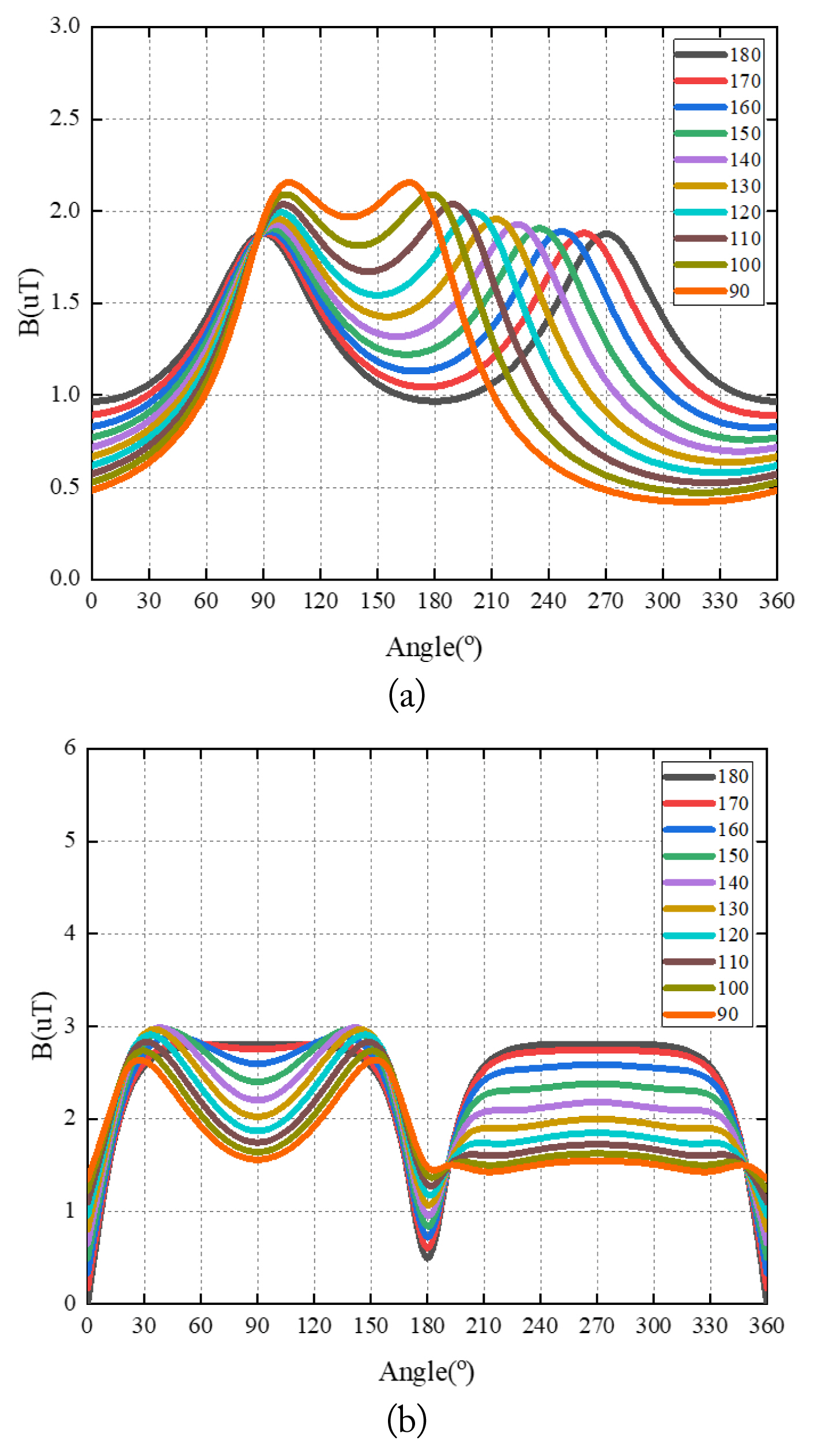
As shown in Fig. 3(a), the variation of B indicates that the transmission performance of the 90┬░ curved coil is better than that of the other coils. The variation of the WAAŌĆÖs B is smaller than that of the NAA. Therefore, the WAA can be used only to enhance transmission performance. However, the 90┬░ curved coil also covers the smallest area, so good transmission performance is achieved in a limited area.
As shown in Fig. 3(b), the ŽĢ movement divides the space into two equal parts, and the B value of the FCC is greater than that of the RCC. This change is consistent with the 180┬░ coil in the Tx design, but the transmission performance of the FCC is enhanced.
We can conclude the following:
The curved coil can enhance the transmission performance of the front area.
As the curved angle widens, the area of high transmission performance shrinks.
The ŽĢ movement divides the space evenly, but the ╬Ė movement does not.
To design the quasi-omnidirectional Tx, we verify the above conclusions by conducting experiments on the curved coils.
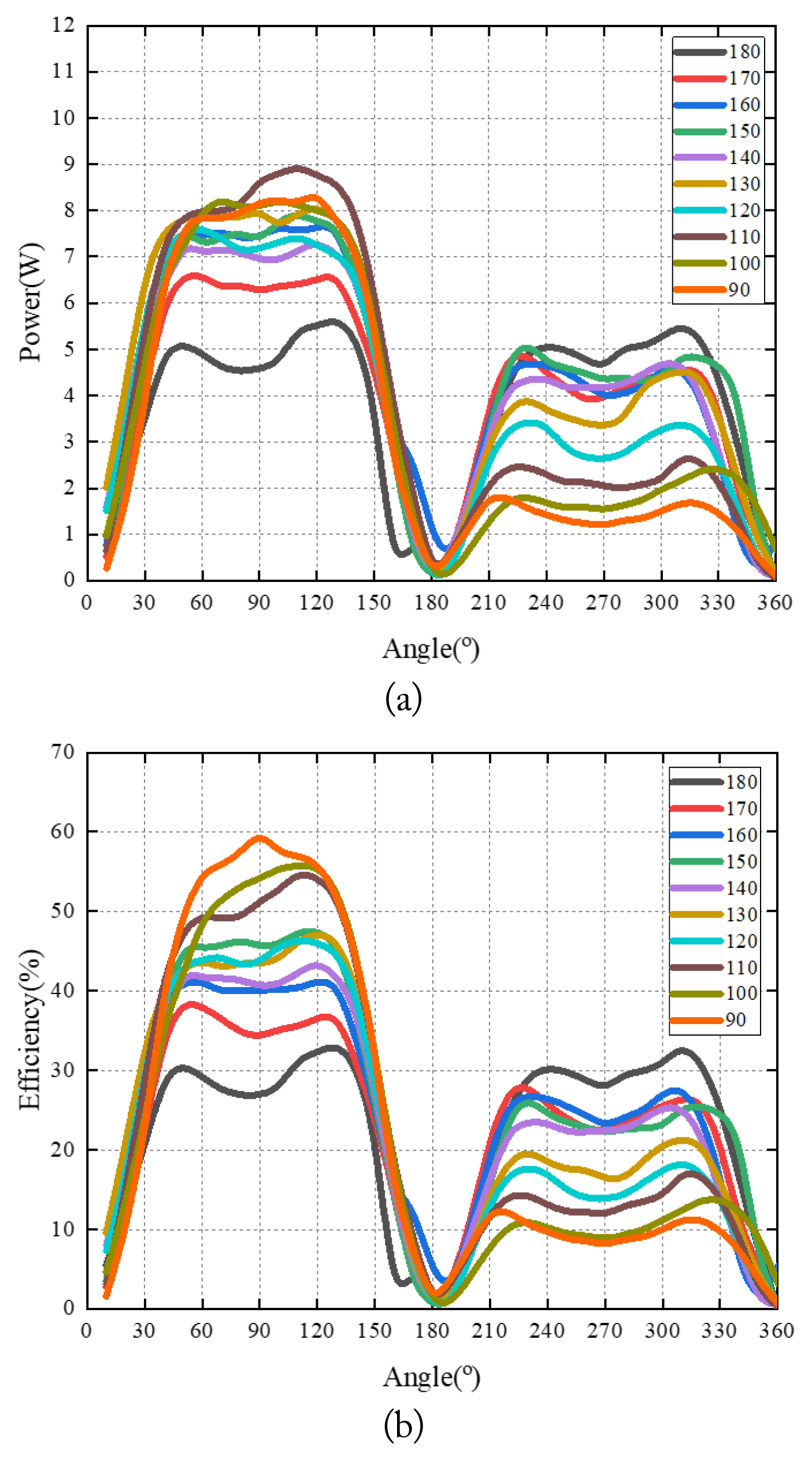
The power and efficiency trends shown in Fig. 4 are similar to those shown in Fig. 3(a). In the NAA, narrower curved angles have better transmission performance. The transmission performance of the 180┬░ coil is significantly weaker than that of the other coils, and the coverage area of the 90┬░ coil is the smallest. In the WAA, the 160┬░ coil shows the best transmission performance and the largest coverage area. Therefore, the 160┬░ coil is the optimal coil for the ╬Ė movement.
The power and efficiency trends shown in Fig. 5 are similar to those shown in Fig. 3(b). The space is divided into two equal parts. The transmission performance of the FCC is better than that of the RCC. In the FCC, the 90┬░ coil has better transmission performance, whereas in the RCC, the 180┬░ coil has better performance. Their coverage areas are basically the same. We can conclude that the 90┬░ coil is the optimal coil for the ŽĢ movement.
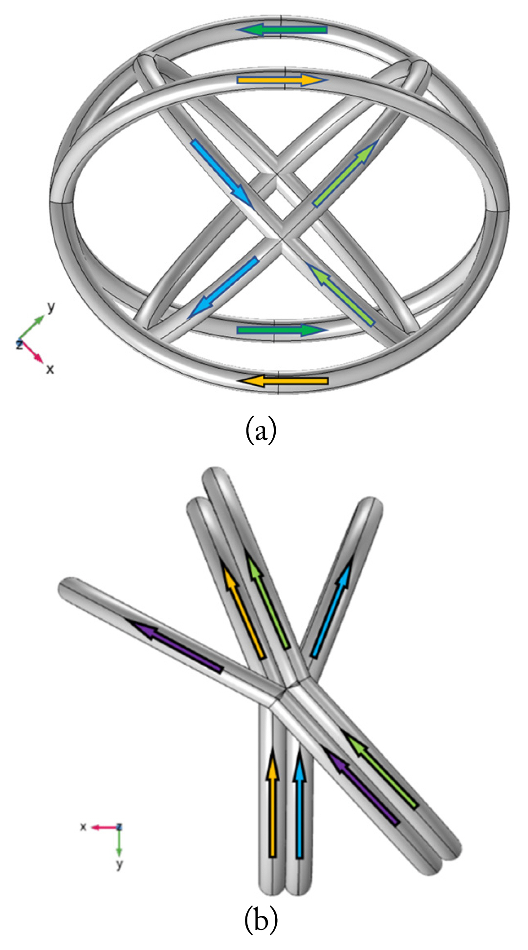
In summary, the 160┬░ coil is the optimal coil for the ╬Ė movement, and the 90┬░ coil is the optimal coil for the ŽĢ movement. Therefore, we design two curved-coil Txs, CTx1 and CTx2, as shown in Fig. 6. CTx1 is composed of four 90┬░ coils. Two opposite coils form a pair, and the current of the opposite coils is reversed, canceling out the magnetic field. The magnetic field of the 90┬░ coil is small in the RCC, so its influence is reduced. Two pair are perpendicular to each other, as shown in Fig. 6(a). CTx2 is composed of four 160┬░ coils. To expand the effective charging area and reduce the angle of the same current, the coils are combined irregularly. In each pair, one side of one coil overlaps with one side of the other. Moreover, one side of one pair overlap with one side of the other, as shown in Fig. 6(b).
IV. Experimental Verification
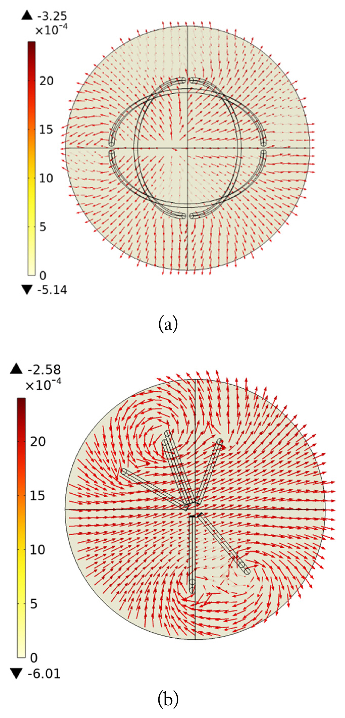
Based on the principles of the curved-coil Tx presented above, we evaluate quasi-omnidirectional Tx prototypes. The radius of the coils is set to 50 mm, while the radius of the copper wire is 2 mm. The current on each side of the curved coil is supplied by a single source and generates a magnetic field surrounding the resonant loop. Fig. 7 shows the top view of the magnetic field of the curved-coil Tx. The B distribution of CTx1 is sparse but relatively uniform, whereas that of CTx2 is denser but has two sparse areas. CTx2 has better transmission performance than CTx1, but it also has a dead zone. The reason for this is that the direction of the rotating magnetic field is parallel to the Rx at the dihedral angle of the same current. The transmission performance of CTx1 is relatively stable. The simulated distributions of the magnetic field vectors generated by the Tx coils agree well with the theoretical analysis presented above.
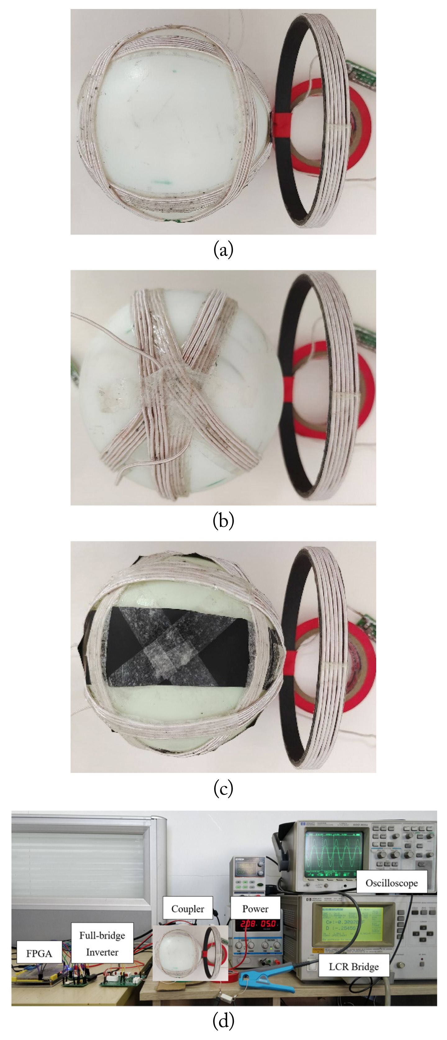
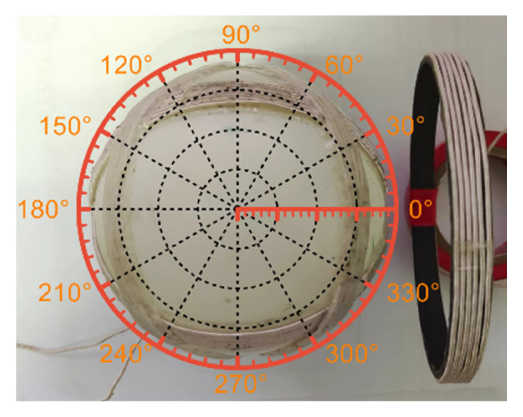
Fig. 8 shows the experimental equipment used to verify the proposed QWPT system. The CTxs are shown in Fig. 8(a)ŌĆō8(c). The coilsŌĆÖ parameters are shown in Table 1. The CTxs are made from a Litz wire. As shown in Fig. 8(d), the CTxs are placed in the xoy plane. All coils are tuned to the design frequency using NPO capacitors. The experimental frequency is set to 100 kHz, which is slightly different from the design frequency due to the use of a compensation capacitor. For the power source, a full-bridge inverter is built using four MOSFETs (IRLL024NPbF). The load resistance is connected to the Rx coil. The input voltage (Vin) is 5 V, and the load is 1 ╬®. The input current (Iin), VRMS, and IRMS of the load are recorded at 10┬░ intervals to calculate the transmission power and efficiency, as shown in Fig. 9. The Rx is manually rotated counterclockwise around the origin of coordinate in the xoy plane from ╬Ė = 0┬░ to ╬Ė = 360┬░ on coordinate paper, with the distance between the Rx and the center fixed at 50 mm.
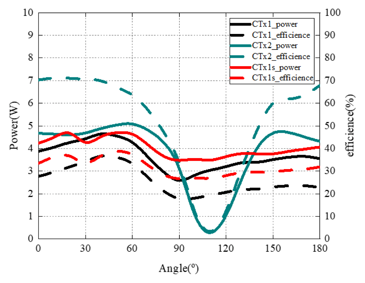
The experimental transmission performance results are shown in Fig. 10. Efficiency is measured from the DC power sources to the AC load.
The transmission performance of CTx1 is basically stable at 0┬░ŌĆō360┬░ but its average efficiency is 27%. The reason for its inefficiency is that the magnetic inductions of opposite coils cancel each other out. CTx1 does not have the same current direction, so dead zones are avoided. To reduce the influence of the opposite coils, we add a magnetic shielding material to CTx1, obtaining CTx1s, which has significantly improved transmission performance. Because the bent magnetic shielding material will shark, we cannot cover all the spheres, but we demonstrate that adding a magnetic shielding material can improve transmission performance.
CTx2 has stable transmission performance at 30┬░ŌĆō60┬░ and 150┬░ŌĆō330┬░ but it also has two dead zones at 0┬░ and 120┬░ because the magnetic field is parallel to the Rx at the dihedral angle of the same current, and the magnetic inductions of the other coils do not fill the two points. Adjusting the combination of the 160┬░ coils will increase the number or size of dead zones. Due to the existence of dead zones, the magnetic field of CTx2 is not uniform. The dead zones are located between two Tx coils with the same current direction. The adjacent coils with the same current direction cause the B of Tx to be parallel to the Rx, so the system cannot transmit power.
A comparison between the proposed QWPT systems and previously proposed structures is presented in Table 2. Previously proposed structures are based on orthogonal coils that require complex control methods and multiple sources [25ŌĆō27]. On the other hand, the CTxs presented in this article offer a completely 2D omnidirectional WPT system with a single source.
V. Conclusion
This paper presents a new quasi-omnidirectional Tx based on curved coils. An equivalent circuit is derived, and a mathematical analysis is performed to specify the resonant coupling operation. The 160┬░ coil is the optimal coil for the ╬Ė movement, while the 90┬░ coil is the optimal coil for the ŽĢ movement. CTx2 has an average efficiency of 63% with 4.45 W at 30┬░ŌĆō60┬░ and 150┬░ŌĆō330┬░ but it also has two dead zones. CTx1 can deliver power of 4.41 W to the Rx coil arranged around it with an efficiency of approximately 27% at an operating frequency of 100 kHz and an optimal separation of 50 mm. By adding a magnetic shielding material, the efficiency can rise to 32%. Low-cost fabrication without using a current control methodology was implemented to verify the practical design of the quasi-omnidirectional curved-coil Tx with a single Rx.
CTx1 does not have a dead zone but has relatively low efficiency, the efficiency of the QWPT system can be increased by placing metamaterial slabs around the CTx1 coil. The FCC of the curved coil can enhance transmission performance, so it can be used in other charging fields.