Design of a UWB Antenna with Multiple Ports on a Single Circular Radiator for Direction-Finding Applications
Article information
Abstract
This paper proposes a single circular radiator with a multi-port (SRMP) antenna that can estimate the direction-of-arrival (DoA) in the azimuth and elevation directions. The proposed SRMP antenna is designed to minimize the size of the ultra-wideband system by using only one patch radiator. To verify the feasibility, the proposed antenna is fabricated, and the reflection coefficient and boresight gain are measured (−13.3 dB and 3.4 dBi at 8 GHz). Then, to observe the direction-finding performance, the DoA estimation results using the Bartlett beamformer are compared with the typical array. At all incident angles, a root-mean-square error of less than 1° is observed when the signal-to-noise ratio is higher than 6 dB.
I. Introduction
Recently, interest in distance estimation and direction-finding technology using ultra-wideband (UWB) has been increasing in various fields, such as the Internet of Things (IoT), vehicles, and smartphones [1–7]. A UWB system typically uses one transmit antenna and two or more receive antennas to estimate the direction-of-arrival (DoA) in the azimuth and elevation angles through phase difference [8, 9]. Therefore, when a UWB system is employed on a portable device, at least three antennas should be mounted to estimate the DoA in various directions. However, as portable devices are miniaturized, the size of the UWB array system must also be miniaturized [10]. Some studies have reduced the size of the antenna element [11, 12], such as corrugated edge structures [13], slotted radiators [4, 14, 15], and slot utilization on the ground plane [16, 17]. Although the antenna is miniaturized using these techniques, a relatively large space is still required to mount the array system. Recently, single radiator antennas were proposed to reduce the mounting space and simplify the array system [12, 18, 19]. However, these antennas were designed for ISM band, 5G MIMO communications, or L-band applications. Therefore, direction-finding UWB antennas that can be mounted on smart devices must still be investigated.
In this paper, we propose a UWB antenna using a single circular radiator with multiple ports (SRMP) to estimate the DoA. The proposed SRMP antenna is designed with multiple feeding ports in a single circular patch to minimize the UWB system by reducing the radiating elements. The UWB is a communication method that uses the wideband of above the 500 MHz frequency band as defined by the Federal Communications Commission [20]. In general, the UWB band is defined from 3.1 GHz to 10.6 GHz according to 14 channel bands separated by the 500 MHz bandwidth [21]. In the Republic of Korea, only band 9 (7.737–8.236 GHz) is permitted as a UWB communication bandwidth for mobile devices. Therefore, the single circular patch is optimized on the FR-4 substrate to operate at 8 GHz, which corresponds to band 9 of UWB communications. Then, the three feeding ports are circularly arranged at intervals of 120° to estimate the DoA in the azimuth and elevation directions. To verify the feasibility, the proposed SRMP antenna is fabricated, and the antenna characteristics, such as the reflection coefficients, mutual couplings, and radiation patterns, are measured in a full anechoic chamber. To observe the direction-finding performance, the DoA estimation results using the Bartlett beamformer and the root-mean-square (RMS) error according to the signal-to-noise ratio (SNR) are obtained in the xy-plane. We then compare the DoA estimation performance of the proposed antenna with the typical circular array. The results demonstrate that the proposed antenna has an advantage in DoA estimation and is suitable for UWB direction-finding applications.
II. Geometry and Performance of the Proposed Antenna
Fig. 1 presents the geometry of the proposed UWB antenna using a single circular patch radiator with multiple ports. The proposed SRMP antenna is designed considering the limited mounting space of smart devices by using a single circular patch that can fit into a small UWB system. Thus, the UWB antenna is designed on an FR-4 substrate with a diameter of l (0.53λ at 8 GHz) and a height of h (0.04λ at 8 GHz). A circular patch radiator with a diameter of d operating at 8 GHz is printed on the substrate, as shown in Fig. 1(a). Then, the three ports are arranged in a circle with intervals of φ0 at a distance of r0 from the antenna center. The proposed SRMP antenna is modeled and simulated using the FEKO EM simulator, and the detailed optimized parameters are listed in Table 1. Photographs of the fabricated SRMP antenna, which is printed on the circular FR-4 substrate, are shown in Fig. 2. The proposed antenna is fed by three RG-402 cables that have low loss characteristics in the UWB frequency bands, as shown in Fig. 2(b).
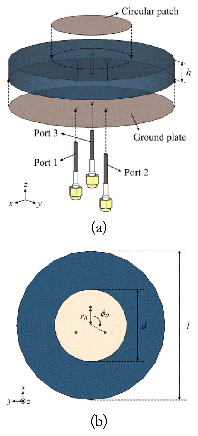
Geometry of the proposed antenna: (a) isometric view and (b) bottom view.

Geometric parameters of the proposed antenna
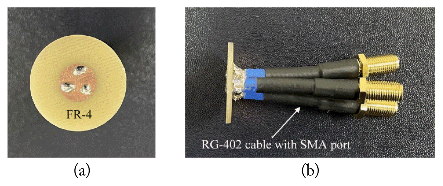
Photographs of the fabricated antenna: (a) top view and (b) side view.
The comparisons of the reflection coefficients and mutual couplings are shown in Fig. 3. The operating frequency band observed at port 1 has a bandwidth of 600 MHz (7.6–8.2 GHz) in the measurement and 500 MHz in the simulation. The proposed SRMP antenna is designed for UWB band 9, which requires a bandwidth of at least 500 MHz, because only band 9 (7.737–8.236 GHz) is permitted as a UWB communication bandwidth in Korea. The simulation of −12.1 dB agrees well with the measurement of −13.3 dB at 8 GHz. Mutual couplings are obtained between port 1 and port 2. The measured and simulated mutual couplings are −8.9 dB and −8.8 dB at 8 GHz, respectively. Considering the close port spacing of 4.5 mm (0.12λ), these coupling values can be regarded as relatively low values for small array systems. Of course, it is clear that an array system using multiple radiators with array distance has better isolation characteristics than a single radiator antenna. However, it is difficult to apply it to mobile smart devices, where the physical size of the antenna should be very small. Therefore, for the first time, we propose an SRMP antenna with the 600 MHz bandwidth as the second-best choice despite the low isolation characteristics.
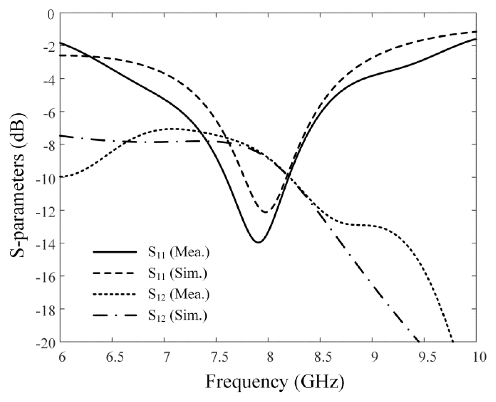
Measured and simulated reflection coefficients and mutual couplings of the proposed antenna.
The measured and simulated 2D radiation patterns of the proposed antenna in the zx- and zy-planes at 8 GHz for port 1 are shown in Fig. 4. The measured and simulated boresight gains are 3.4 dBi and 3.2 dBi, respectively. These results demonstrate that the proposed SRMP antenna is suitable for use in UWB applications despite the couplings due to the narrow port spacing.
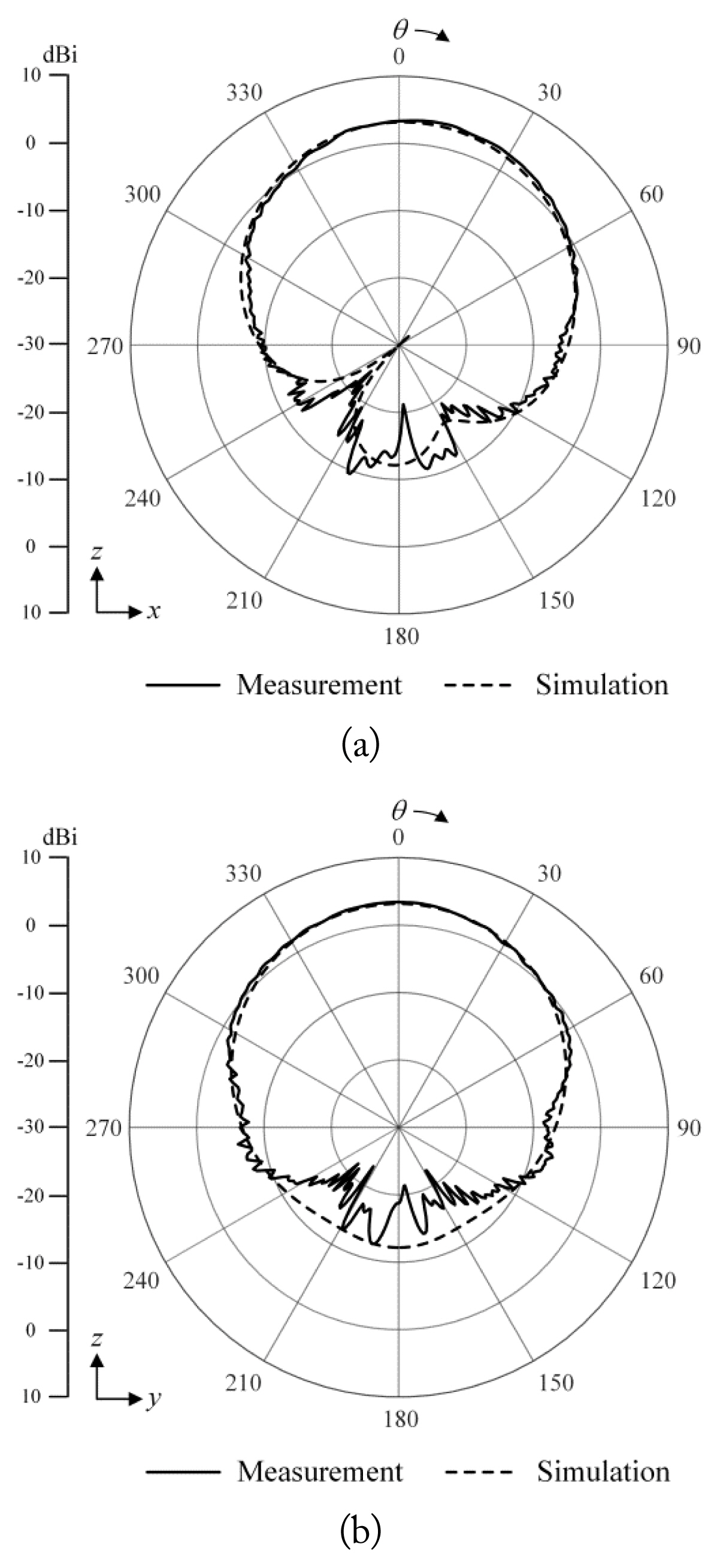
Measured and simulated radiation patterns of the proposed antenna at 8 GHz: (a) zx-plane and (b) zy-plane.
III. DoA Estimation using the Bartlett Beamformer
To examine the DoA estimation performance of the proposed antenna, the Bartlett beamformer, which is an extension of classical Fourier-based spectral analysis for array systems, is utilized. First, the received signal x(t) in each antenna port is defined in Eq. (1). Vector x(t) is the signals acquired at each port by the steering vector a(φ) of the array antenna, where an incident signal s(t) is a continuous sine wave:
Vector n(t) is additive white Gaussian noise for each port. The measured and simulated E-field (Eθ) radiation of the proposed antenna is shown in Fig. 5(a). It will be used as the steering vectors. To compare the DoA estimation performance of the proposed SRMP antenna with the typical array, we also simulate the E-field (Eθ) of a circular array with three antennas, as shown in Fig. 5(b). As can be seen, the maximum radiation of each pattern is oriented toward the direction in which each feeding port is placed. Then, the Bartlett beamformer denoted by Eq. (2) and Eq. (3) is used to examine the direction-finding performance. Vector R is a covariance matrix of signal vectors that carries the spatial and spectral information of the incident signals, as expressed in Eq. (4):
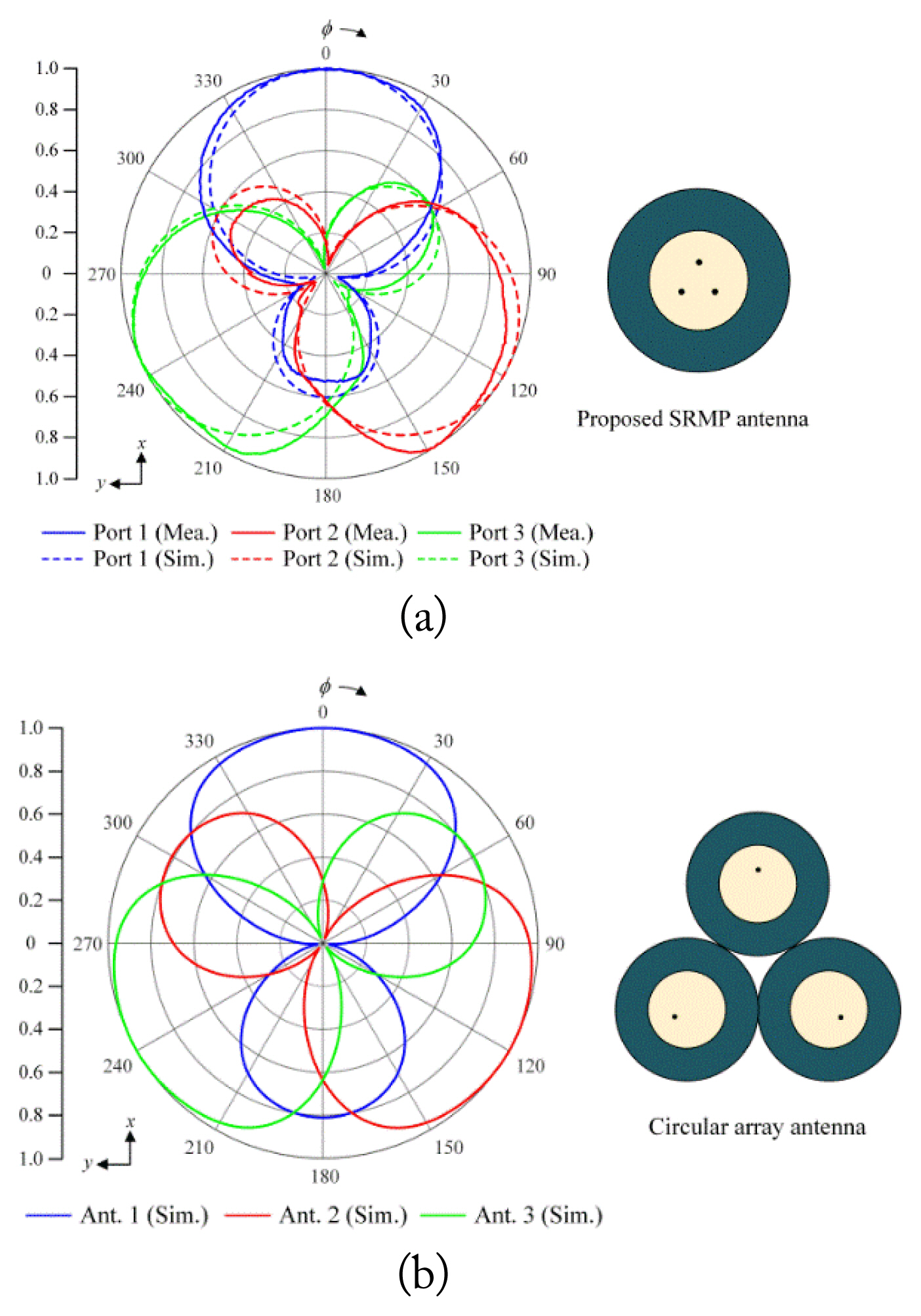
E-field radiation in the xy-plane: (a) proposed SRMP antenna and (b) circular array antenna.
The power spectrum Pmea can be derived with the steering vector amea obtained by the measured radiation pattern. Psim is derived with the steering vectors asim obtained by the simulated radiation pattern. This algorithm provides the maximum power spectrum at a given incident angle.
The power spectrum of the Bartlett beamformer in terms of the different incident angles are shown in Fig. 6. It is assumed that the SNR is 10 dB. In the first case, the signal is incident at φ1 = 30° on the xy-plane, and in the second case, it is φ2 = 120°. The results computed with the measured and simulated data agree well (φ = 30° and φ = 29°, φ = 118° and φ = 117° for each incident angle), as shown in Fig. 6(a). The proposed antenna has an advantage in DoA estimation because the directivity of each pattern can improve the resolution of the power spectrum. The typical circular array with three antennas also has similar estimated angle results (φ = 29° and φ = 119° for each incident angle). However, the peak of the power spectrum is broad, as shown in Fig. 6(b), which leads to a lower resolution compared with the proposed SRMP antenna. In addition, we investigated the DoA estimation results in the elevation direction (in the zy-plane) to confirm that the proposed antenna is capable of direction-finding in the azimuth and elevation directions. The power spectrums of the Bartlett beamformer in the zy-plane with two different incident angles of θ1 = 0° and θ2 = 30°, as shown in Fig. 7. The DoA estimated by the measured radiation patterns has θ = 0° and θ = 31° as indicated by the solid and dotted lines, respectively. As expected, the results in the zy-plane show a more accurate DoA estimation compared to the results in the xy-plane.
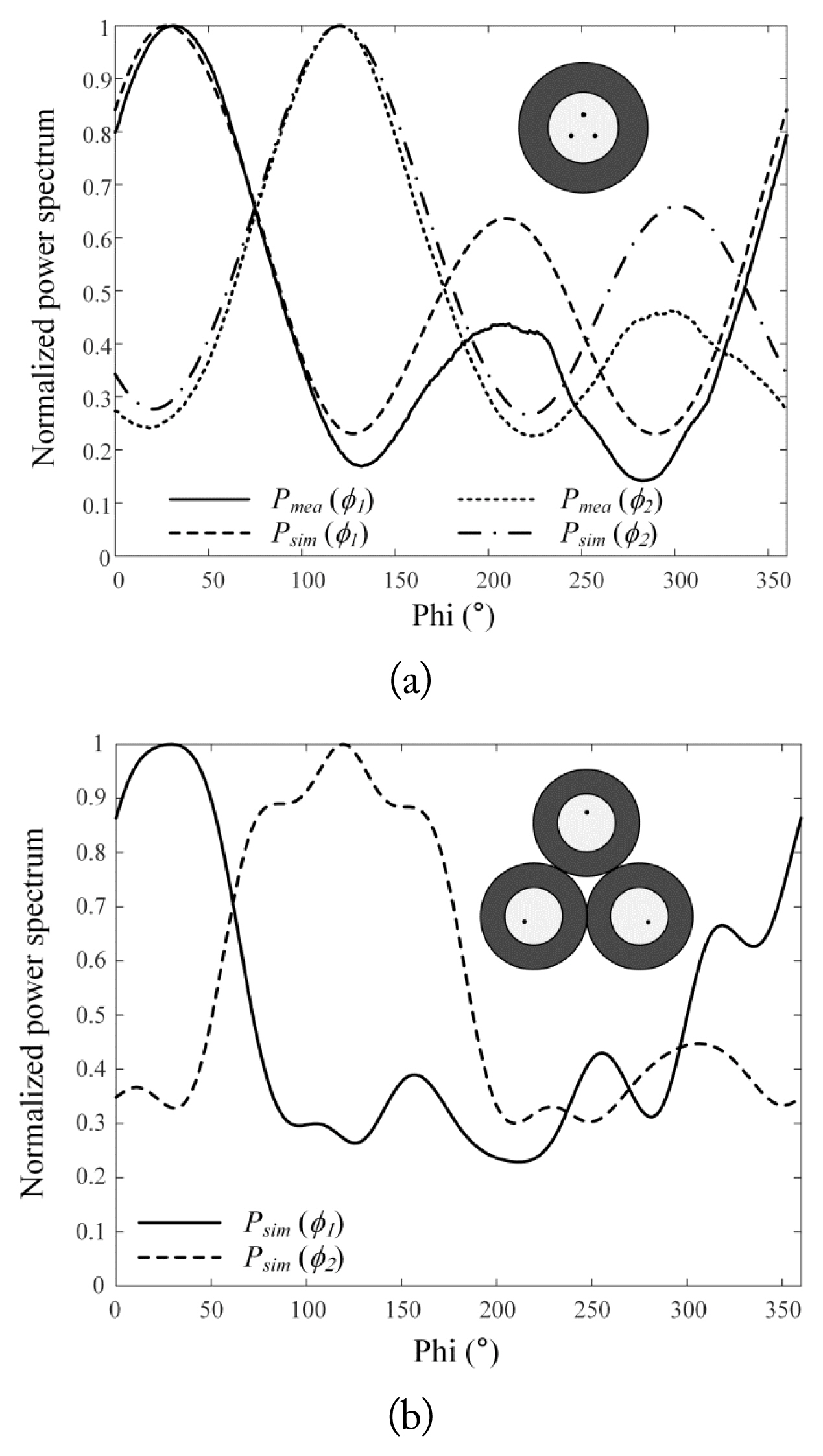
Normalized power spectrum with variations in the incident angle: (a) proposed SRMP antenna and (b) circular array antenna.
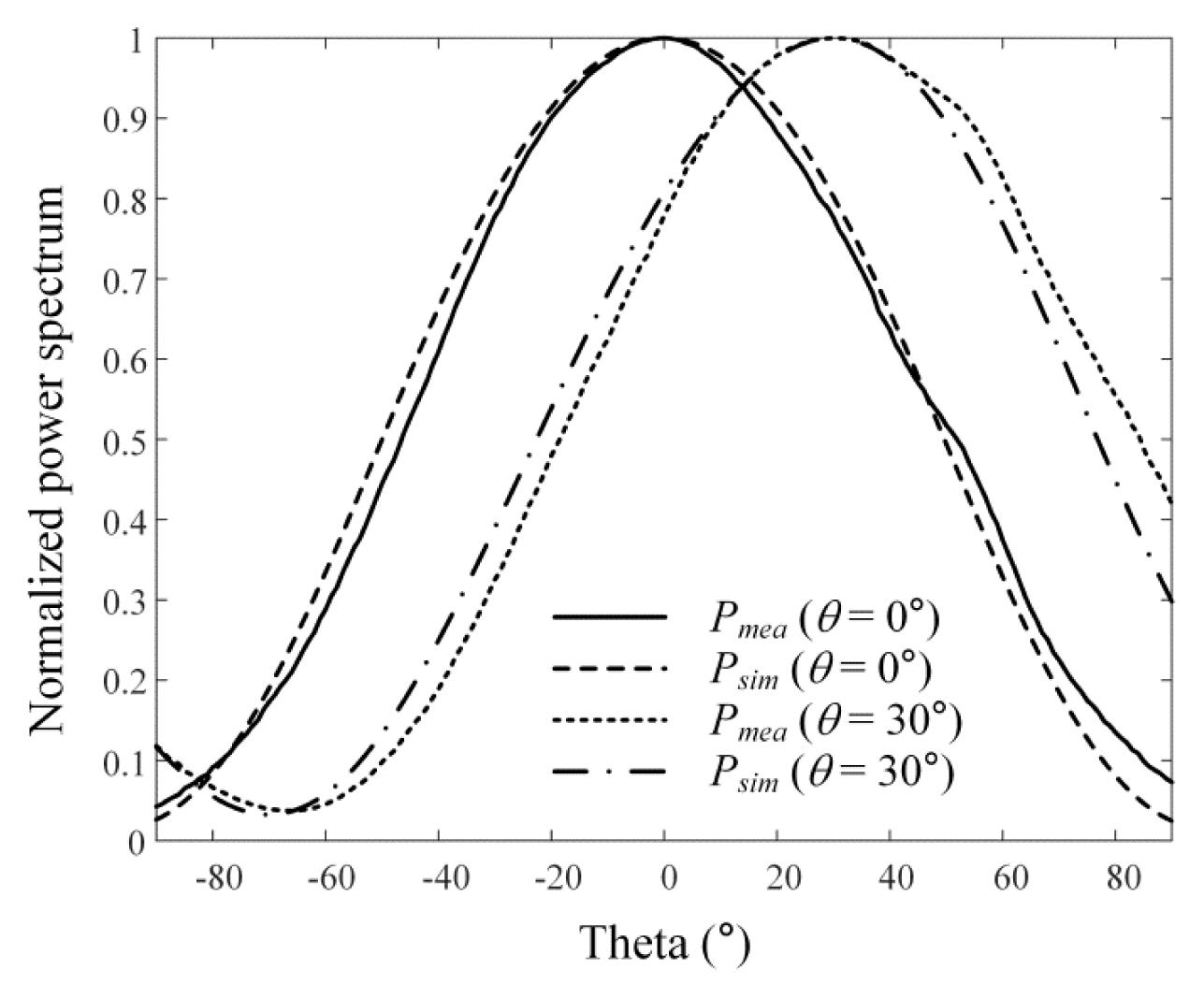
Normalized power spectrum corresponding to the incident angle in the zy-plane.
Fig. 8 shows the RMS error of the DoA estimation as a function of the SNR. The RMS error is calculated by the RMS difference between the actual and estimated signal directions for all incident angles in the xy-plane. To obtain the results, the average RMS error is computed with 100 iterations with random noise characteristics [18]. The RMS errors obtained using Pmea and Psim are indicated by the solid and dashed lines. As expected, the RMS error decreases as the SNR increases. The proposed SRMP antenna and the circular array have an RMS error of less than 1° when the SNR is higher than 6 dB. The results verify that the proposed SRMP antenna is suitable for UWB direction-finding applications, despite using only one patch radiator.
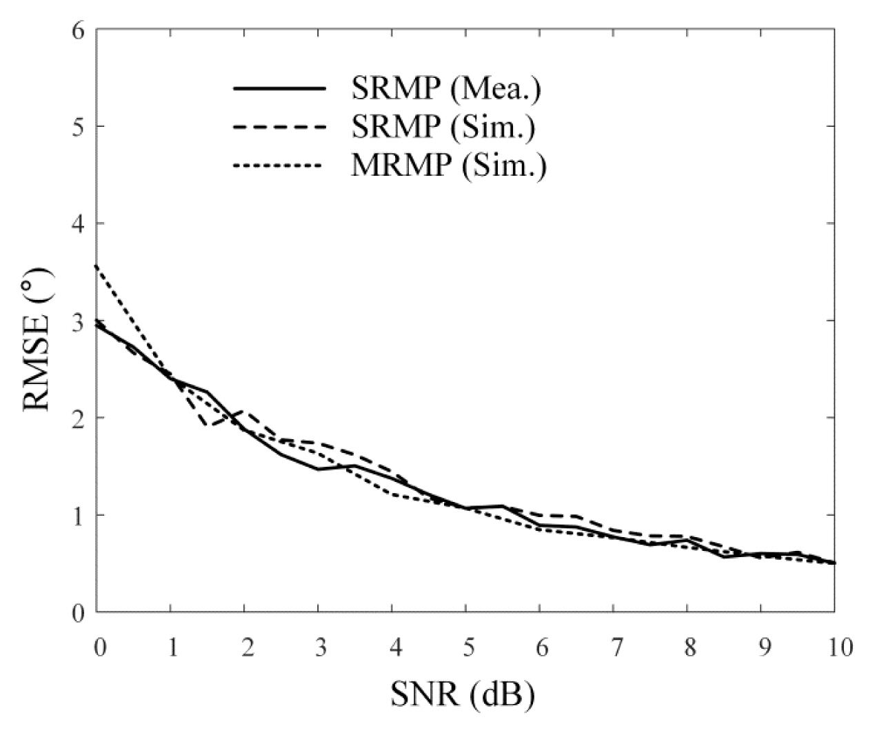
Root-mean-square error (RMSE) according to the SNR for all incident angles in the xy-plane.
IV. Conclusion
In this paper, we proposed a UWB SRMP antenna that can estimate the DoA using a single circular patch radiator. The single circular patch was optimized to operate at 8 GHz. Then, the three feeding ports were circularly arranged to achieve the DoA estimation in the azimuth and elevation directions. The proposed antenna simulated and measured reflection coefficients of −12.1 dB and −13.3 dB with a measured boresight gain of 3.4 dBi at 8 GHz. To observe the direction-finding performance, the DoA estimation results were obtained at incident angles of 30° and 120°. The power spectrums calculated from the measured and simulated patterns agreed well with each other as 29° and 30° and 118° and 117° for each incident angle, respectively. In addition, the RMS error in every incident angle was found to be less than 1° when the SNR was higher than 6 dB. The results verified that the proposed SRMP antenna was suitable for UWB direction-finding applications, despite using only one patch radiator.
Acknowledgments
This research was supported by the Samsung Research Funding Center of Samsung Electronics (Project No. SRFCIT1801-51).
References
Biography

Sangwoon Youn received his B.S. and M.S. degrees in electronic and electrical engineering from Hongik University, Seoul, South Korea, in 2019 and 2021, respectively, where he is currently pursuing his Ph.D. degree in electronic and electrical engineering. His research interests include EMI and EMC, wave propagation, UWB antennas, 5G application, direction-finding, and anti-jamming systems.

Byung-jun Jang received his B.S., M.S., and Ph.D. degrees in electronic engineering from Yonsei University, Seoul, Korea, in 1990, 1992, and 1997, respectively. From 1995 to 1999, he was with LG Electronics, Seoul, where he developed code-division multiple-access (CDMA) and digital enhanced cordless telecommunication (DECT) RF modules. From 1999 to 2005, he was with the Electronics and Telecommunications Research Institute (ETRI), Daejeon, Korea, where he performed research in the fields of satellite RF components and monolithic microwave integrated circuits. In 2005, he joined Kookmin University, Seoul, where he is with the Department of Electrical Engineering. He is currently interested in the areas of RF circuit design, radio frequency identification (RFID) system design, wireless power transfer (WPT) system design, frequency interference modeling and spectrum engineering, and wireless sensor design.

Hosung Choo received his B.S. degree in radio science and engineering from Hanyang University in Seoul in 1998, and his M.S. and Ph.D. degrees in electrical and computer engineering from the University of Texas at Austin in 2000 and 2003, respectively. In September 2003, he joined the School of Electronic and Electrical Engineering, Hongik University, Seoul, Korea, where he is currently a full-time professor. His principal areas of research are the use of the optimization algorithm in developing antennas and microwave absorbers. His studies include the design of small antennas for wireless communications, reader and tag antennas for RFID, and on-glass and conformal antennas for vehicles and aircraft.