I. Introduction
Step 1. Calibrating a material measurement system including a scattering parameter measuring instrument, such as a vector network analyzer (VNA), to determine the reference planes (#1 and #2) of the measurement system for both sides (#1 and #2) of an MUT between two antennas, as shown in Fig. 1;
Step 2. Measuring the scattering parameters of the MUT using the calibrated material measurement system; and
Step 3. Extracting the material parameters of the MUT from the measured scattering parameters using EM theory.
II. Free-Space Calculable Reflect Standard
III. Free-Space Unknown Thru Measurement
1. Two-Port Eight-Term Error Modeling and Its Cascade Matrix Representation
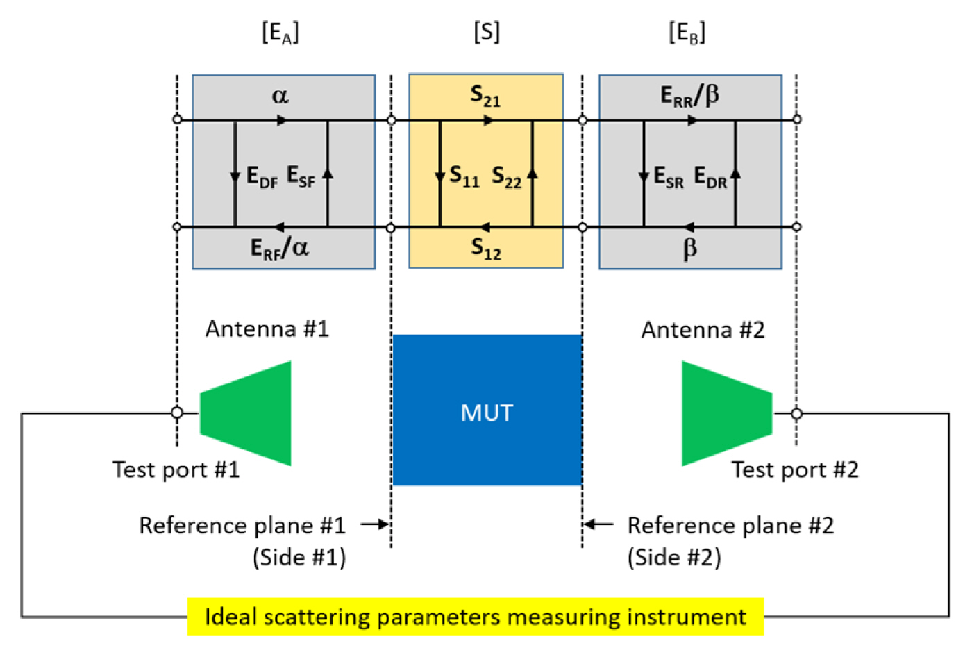
- An MUT is placed at the middle of two antennas (#1 and #2) in free space, where both sides (#1 and #2) of the MUT are assigned to the reference planes (#1 and #2) of the material measurement system;
- An ideal scattering parameter measuring instrument for measuring the scattering parameters of the MUT, where the test ports (#1 and #2) of the measuring instrument are connected to the two antennas (#1 and #2); and
- Two error adapters (EA and EB) describing the non-ideal parts between the reference plane (#1 and #2) and the test port (#1 and #2), modeled as four systematic errors at each side (#1 and #2) of the MUT, where (EDF,ESF,ERF) and (EDR,ESR,ERR) denote the one-port systematic error corresponding to directivity, port match, and reflection tracking, respectively, on each error adapter, while ╬▒ and ╬▓ are the systematic errors related to transmission tracking on each error adapter. Effectively, eight systematic errors can be determined during the calibration of the material measurement system.
2. Procedure of Free-Space Unknown Thru Calibration and Measurement
Step 1. Determining the one-port systematic error (EDF,ESF,ERF) at reference plane #1 by performing the one-port calibration with three free-space reflect standards;
Step 2. Repeating Step 1 to determine the other one-port systematic error (EDR, ESR, ERR ) at reference plane #2, which is situated away from reference plane #1 due to the thickness of an MUT; and
Step 3. Determining the remaining unknown ╬▒/╬▓ by performing an unknown thru measurement. If the MUT, which is placed between the two reference planes (#1 and #2), meets the requirements of the unknown thru standard, it is used as the unknown thru standard in the calibration. Otherwise, an air gap with the same thickness as the MUT is used as the unknown thru standard.
Step 4. If an MUT meets the requirements of the unknown thru standard, its scattering parameters are measured using the calibrated free-space material measurement system without changing the calibration setup. Otherwise, the scattering parameters of the MUT are measured by replacing the air gap with the MUT.
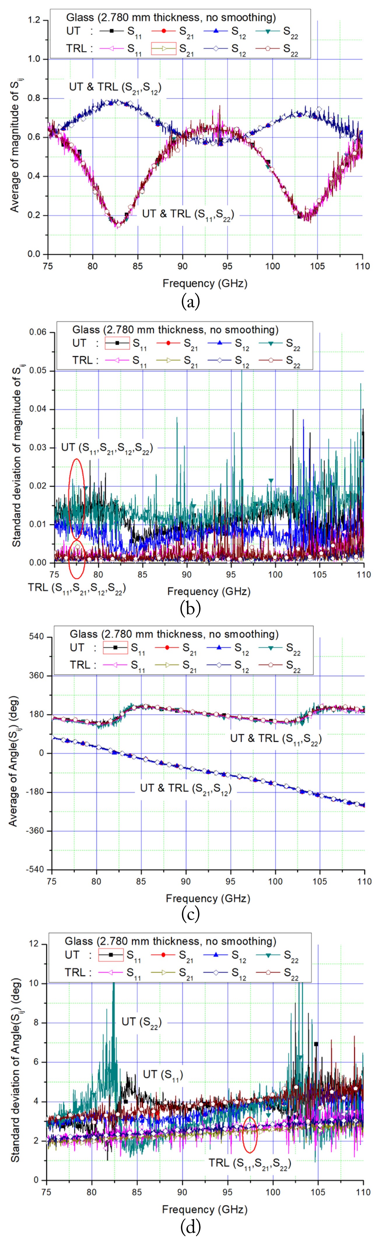
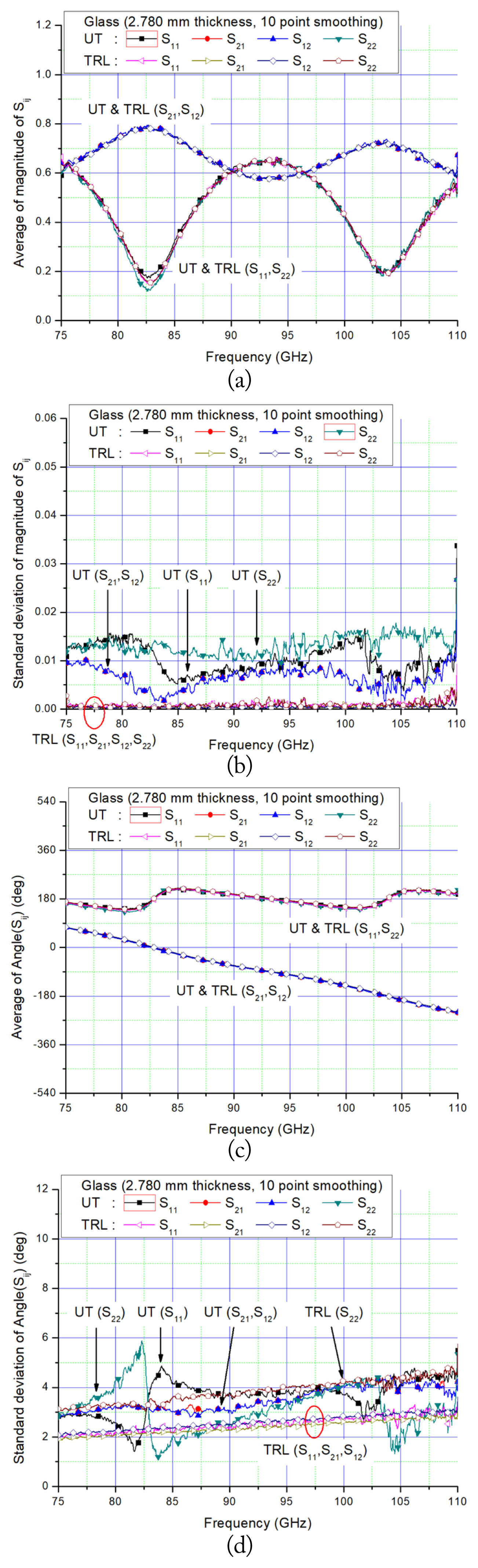
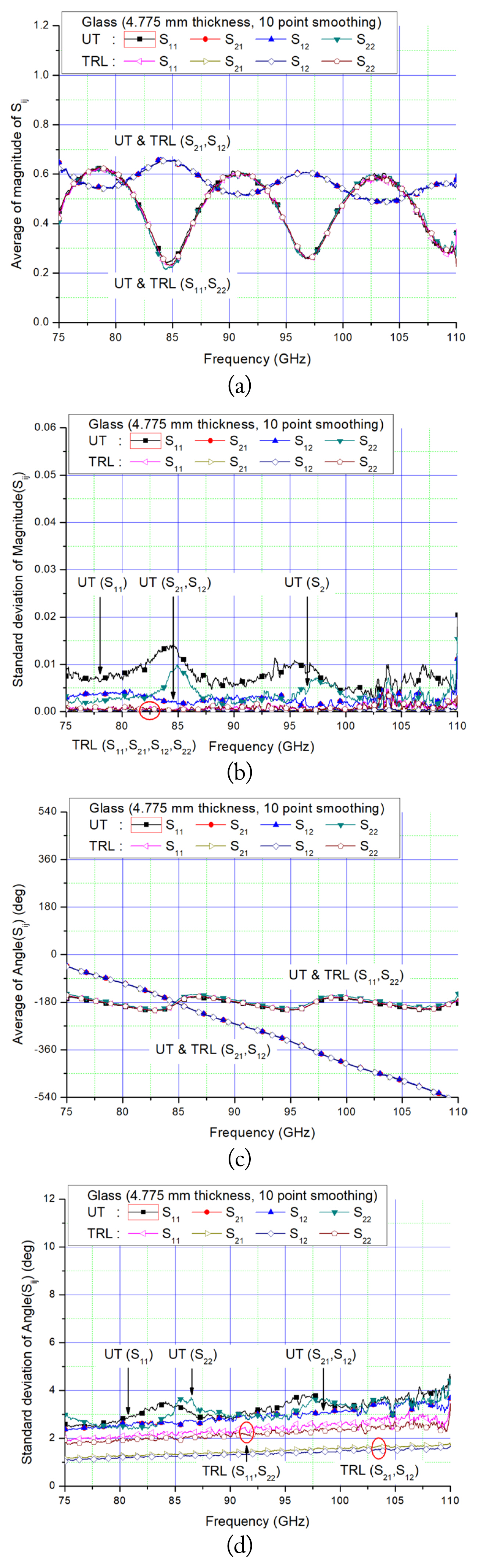
IV. Free-Space Unknown Thru Measurement Results
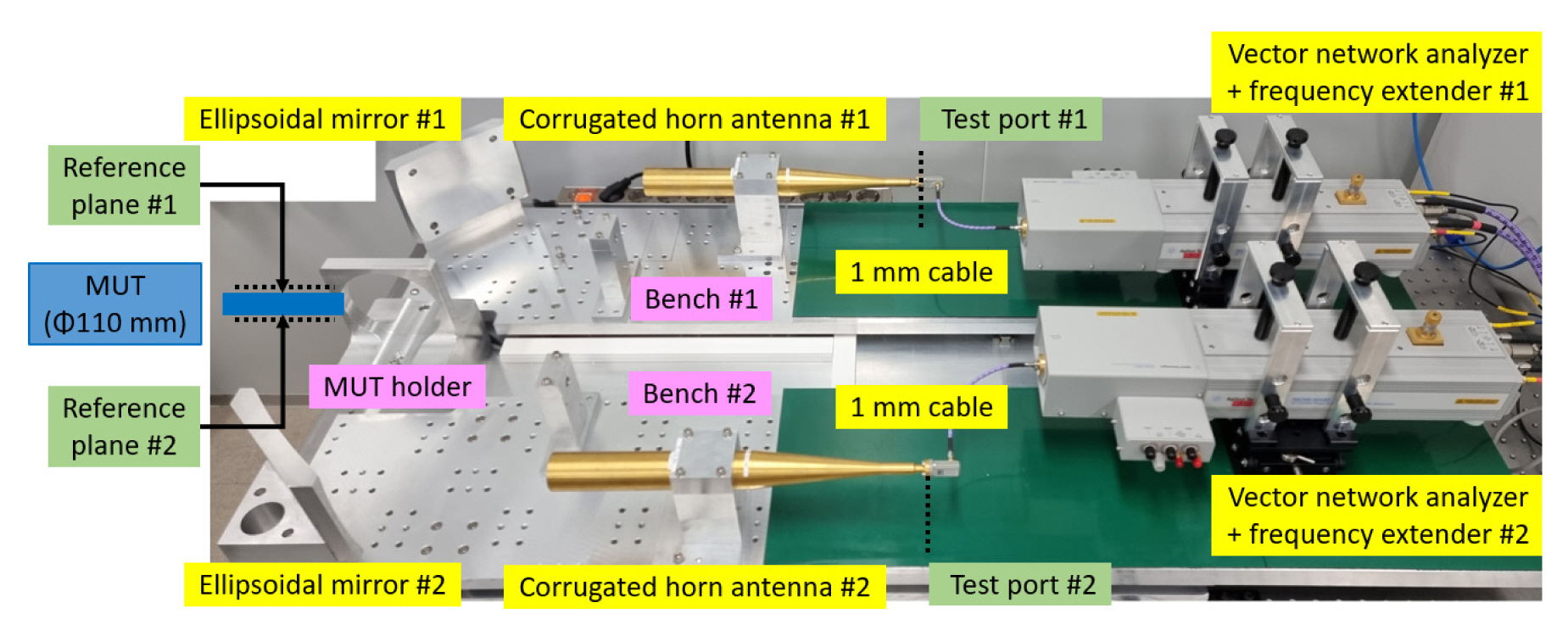
- A millimeter-wave scattering parameters measuring instrument consisting of a VNA and two frequency extenders; and
- A quasi-optic-based free-space instrument composed of two linearly movable benches with an MUT holder between them, where each bench has a Gaussian beam forming corrugated horn antenna and an ellipsoidal refocusing mirror and is capable of independently changing the separation distance between the bench and the MUT holder for supporting TRL calibration.
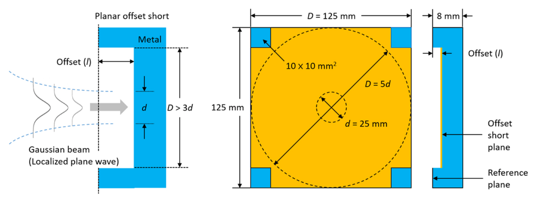
- Free-space unknown thru calibration is carried out by measuring: (i) the one-port calibration at the reference planes corresponding to both sides of the MUT using three planar offset ŌĆ£ShortsŌĆØ (l = 0 mm, 0.550 mm (╬╗/6), 1.100 mm (2╬╗/6)), generating a phase difference of 120┬░ between the reflection coefficients of the planar shorts at the center frequency of the W-band [21], and (ii) the ŌĆ£unknown ThruŌĆØ after inserting an MUT between the two reference planes. Since the two reference planes (#1 and #2) of the measurement system are fixed during the calibration, movement of the RF cable can be avoided. Meanwhile, the reflection coefficients of the three reflect standards used in the one-port calibration should not be equal to each other, and should be distributed as far as possible from each other on the complex reflection plane in the operating frequency range. The theoretical magnitude of the reflection coefficient of the three planar offset shorts (0 mm, 0.550 mm, and 1.100 mm) is unity, regardless of the offset and signal frequency. The theoretical phase of the planar flush (0 mm offset) is ŌłÆ180┬░, irrespective of the signal frequency, while that of the two planar offset shorts is changed from 80.96┬░ to 34.75┬░ for the 0.550 mm offset, and from ŌłÆ18.07┬░ to ŌłÆ110.51┬░ for the 1.100 mm offset in the W-band [21]. Therefore, the three planar offset shorts can be used as independent reflect standards in the one-port calibration; and
- TRL calibration is carried out by measuring: (i) the zero-length ŌĆ£ThruŌĆØ by directly connecting the reference planes (#1 and #2), (ii) the ŌĆ£ReflectŌĆØ using a metal plate (4.671 mm thickness) inserted between the two reference planes, which are consequently separated by the plate thickness, and (iii) the ŌĆ£LineŌĆØ of a quarter-wavelength delay (0.82 mm length) in the air, which separates the reference planes. Since reference plane #1 of the measurement system is fixed during the calibration, movement of the RF cable is inevitable.
- A precise positioning system and movement of RF cables in the TRL method.
- A well-matched broadband EM absorber in the TRM method.
- A time-gating measurement and a planar metal plate that is as thick as a MUT during calibration and a de-embedding process to compensate for the effect of the difference in thickness of the planar metal plate and the MUT in the GRL measurement method.