I. Introduction
Radar sensors that track and detect the positions and crowding densities of targets have been actively studied for various applications because they are less affected by conditions such as light, fog, and humidity compared to vision sensors and LIDAR [1]. Frequency-shift keying (FSK) radar, which is a type of interferometry radar, is useful for short-range detection owing to its high-precision measurement using a narrow-frequency bandwidth. Additionally, it can measure the absolute distance using a simply configured continuous-wave (CW) radar [1ŌĆō4].
The maximum unambiguous range in FSK radar is determined by the maximum phase difference (theoretically 2ŽĆ) from the two distinguished frequencies. If the phase difference for each frequency cannot be measured discriminately, the phase difference measured by ╬Ė cannot be distinguished from 2ŽĆŌĆō╬Ė owing to the periodic characteristics of the trigonometric function. This problem in the phase-difference selection can reduce the maximum unambiguous range from 2ŽĆ to ŽĆ [5]. The maximum unambiguous range corresponding to the phase difference of 2ŽĆ was obtained in previous studies using a frequency control signal in FSK operation as a synchronization signal for the frequency discrimination of baseband signals [6, 7]. However, using the synchronization signal for data acquisition by the receiver increases the complexity of the radar configuration and has limitations in its application to the radar architecture, in which the transmitter and the receiver are spaced apart. The method of monitoring the tuning voltage of the voltage-controlled oscillator (VCO), which can be considered in general, may deteriorate the phase and frequency stability of FSK radar due to the noise introduced by the monitoring terminal [8]. The maximum unambiguous range corresponding to 2ŽĆ can also be obtained without a synchronization signal using a method that continuously measures the phase differences based on previously obtained data within the distance corresponding to ŽĆ [9, 10]. However, the continuous measurement method has limitations in various applications owing to the constraint that the initial distance measurement should be conducted within a distance corresponding to the phase difference of ŽĆ.
In this study, a frequency discrimination method that does not employ a synchronization signal and continuous measurement is proposed. The phase difference in each frequency can be effectively discriminated using the asymmetric duty cycle of the control signal in the VCO, which determines the output frequency of FSK radar. Owing to the asymmetric transmission time of the proposed method, the two frequencies in FSK radar can be easily distinguished by the difference in the number of samples counted in the envelope-detected baseband signals. The measurement results showed that FSK radar, using the proposed method, can obtain the maximum unambiguous range corresponding to the phase difference of 2ŽĆ without degrading detection accuracy. Using the proposed frequency discrimination method, FSK radar uses less memory because it does not require the collection of the control signal.
II. Distance Measurement using the Proposed Frequency Discrimination Method
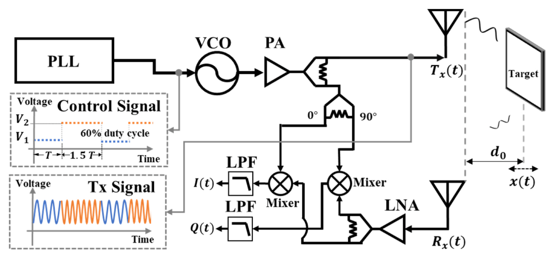
The in-phase (I(t)) and quadrature (Q(t)) signals of FSK radar shown in Fig. 1 can be expressed as
where AI and AQ are the amplitudes of each signal, ╬╗ is the wavelength of the carrier frequency in air, d0 is the absolute distance between the radar and target, x(t) is the small displacement of the target, ŽåI and ŽåQ are the static phase noises, ╬öŽĢ(t) is the residual phase noise (which can be neglected because of the range correlation effect), and DCI and DCQ are DC offset voltages. Neglecting the I/Q imbalance and DC offsets, the phase differences ╬Ėf1 and ╬Ėf2, which are demodulated using the complex signal demodulation, can be represented as
where Žåf1 and Žåf2 are the static phase offsets. These offsets can be compensated for by using a reference target in a fixed position [11]. Assuming x(t) is negligible compared to d0, the difference between ╬Ėf1 and ╬Ėf2 can then be used to obtain d0 as follows:
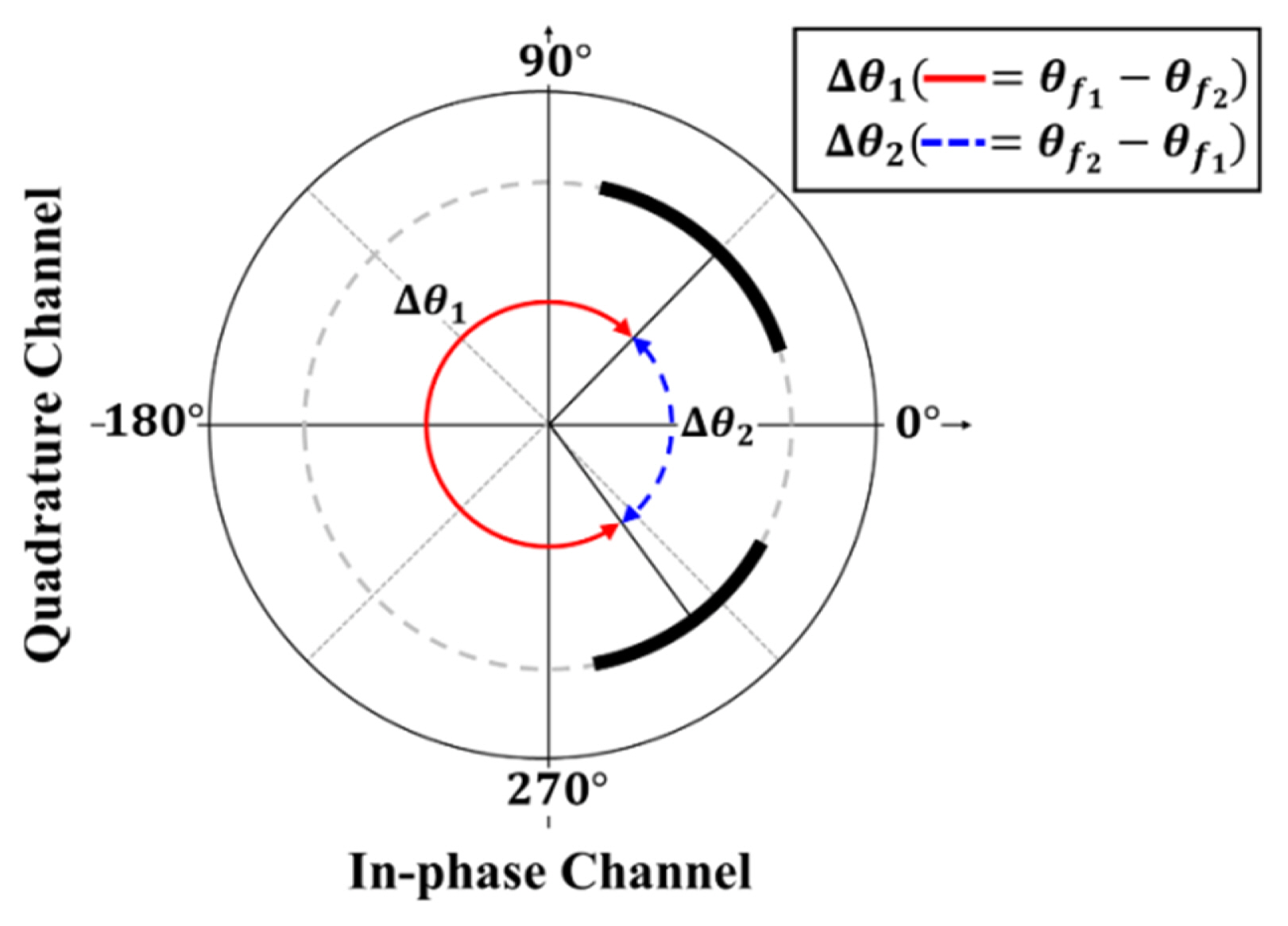
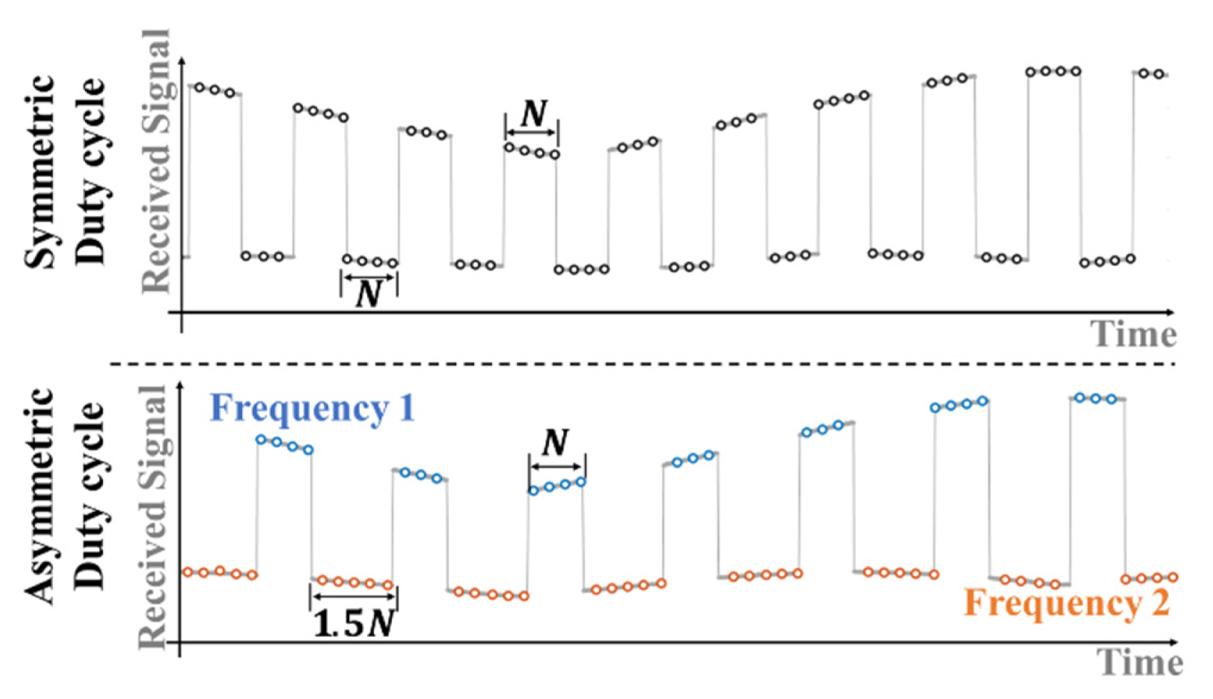
where c is the velocity of light and f1 and f2 are the FSK radar carrier frequencies. FSK radar distance accuracy is determined using the phase noise of the signal generator and the phase measurement error for each frequency. It should be noted that distance accuracy can deteriorate in the presence of environmental clutter [3, 12]. Distinguishing the phase difference for each frequency is indispensable in distance measurements, and the ambiguity of the measurement increases, as shown in Fig. 2, if the phase difference at each carrier frequency cannot be distinguished. This problem is caused by phase-difference selection, which is based on the periodicity of the trigonometric function. Only one of the phase differences ╬ö╬Ėf1 and ╬ö╬Ėf2 shown in Fig. 2 represents the real absolute distance, and the other corresponds to the virtual distance by the ghost target, which is not present in the environment. The asymmetric transmission time in the frequency control of FSK operation makes the durations of the carrier frequencies different from each other. The baseband signals of FSK radar can be extracted into each baseband signal at each carrier frequency from the upper and lower envelopes of the baseband waveforms, owing to the difference between the DC offsets at each frequency [9]. The time duration of each frequency is proportional to the duration in the baseband waveform.
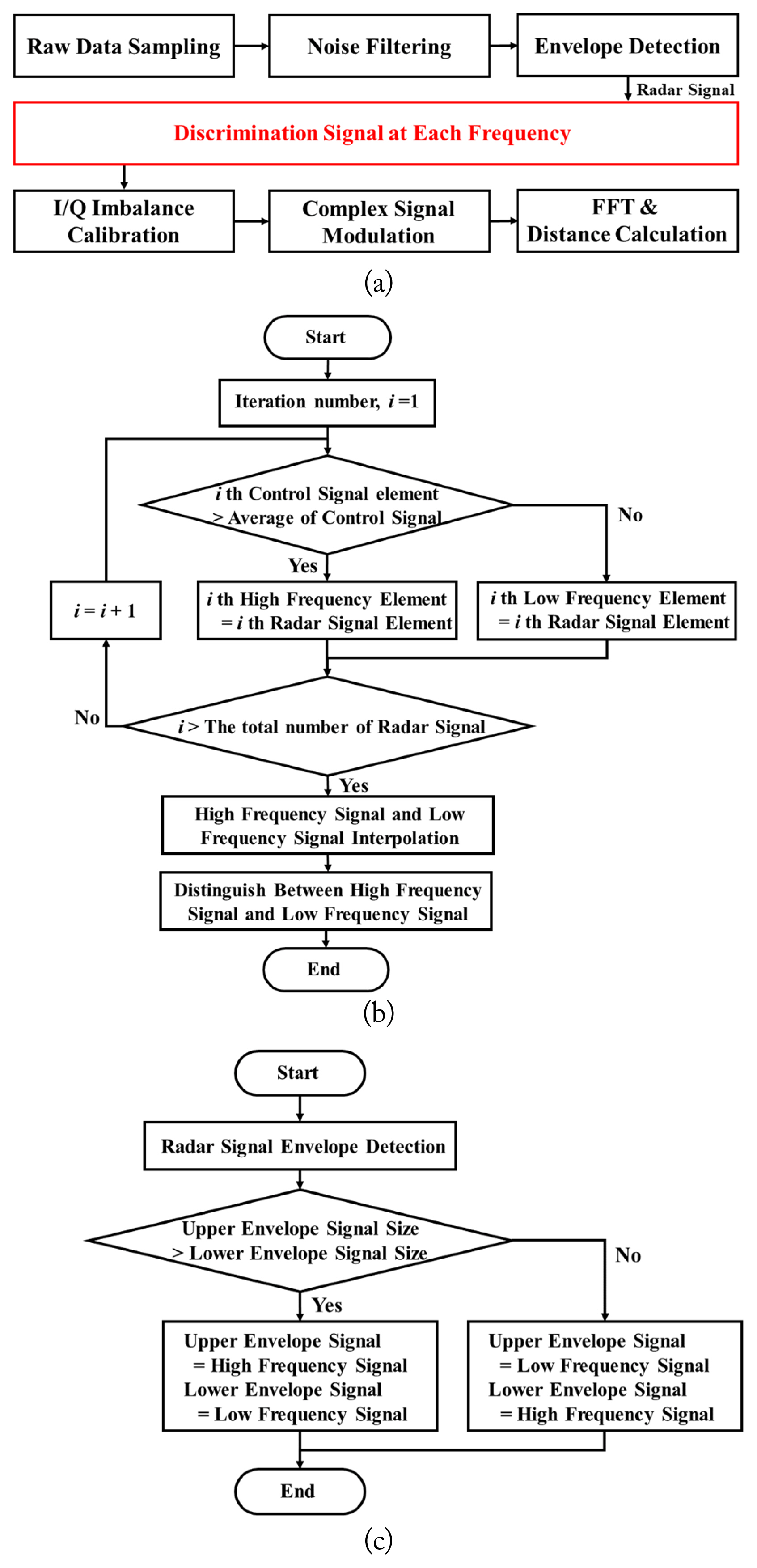
Different durations occur in the baseband waveform owing to the asymmetric transmission time, as shown in Fig. 3. The phase difference for each frequency can easily be distinguished by counting the number of samples for each envelope waveform using a constant sampling frequency. The overall digital signal processing procedure is illustrated in Fig. 4(a). Flowcharts of the conventional frequency discrimination method using a control signal and the proposed method using asymmetric transmission times are shown in Fig. 4(b) and 4(c). In the conventional method, the baseband signal for each frequency is discriminated by synchronizing with the control signal. An iterative process is required to carry out synchronization for each frequency, as shown in Fig. 4(b). In contrast, by using the difference between the number of samples in the upper and lower baseband signal envelopes, the proposed method distinguishes the baseband signal for each frequency without requiring control signal acquisition. This difference in the number of samples was generated by the asymmetric control signal without synchronization with the control signal. For the proposed method, the envelopes were obtained using spline interpolation with non-knot conditions for local maxima in every 50 samples. The calibration of the I/Q imbalance to acquire the accurate phase difference was performed using the GramŌĆōSchmidt procedure [6]. The proposed method can mitigate the ambiguity in the phase-difference selection in FSK radar without using a synchronization signal or previous detection data. Thus, the maximum unambiguous range can be determined as a distance corresponding to the theoretical phase difference of 2ŽĆ in FSK radar using the proposed method.
III. Measurement Results
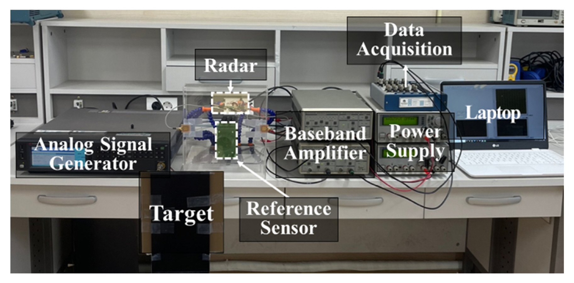
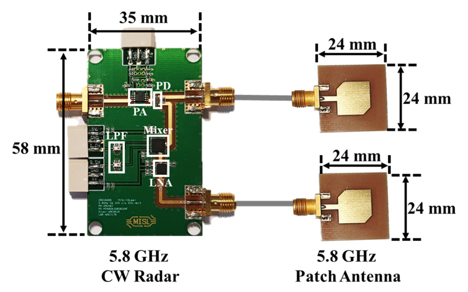
Fig. 5 shows the experimental environment used for absolute distance measurement. FSK radar, which was operated in the 5.8 GHz ISM band, used 5.725 GHz and 5.875 GHz frequencies. In the analog signal generator (Keysight N5183B), the transmitted durations for FSK operation were set to 150 ms for 5.875 GHz and 100 ms for 5.725 GHz. The maximum unambiguous range of 1 m was determined through an operating frequency difference of 150 MHz. The target object consisting of a metal plate with a size of 148 mm ├Ś 140 mm was moved from 1 m to 2 m with 0.1 m intervals for 30 s, which was in the second unambiguous range from the radar. The radar frontend module, including the patch antenna with a gain of 4.03 dBi, was implemented on an FR4 printed circuit board (PCB), as shown in Fig. 6. The transmitted power at the antenna input was measured to be 10 dBm, and the overall gain and noise figures in the receiver were designed to be 16.5 dB and 1.1 dB, respectively. The baseband I/Q signals were acquired with a sampling frequency of 1 kHz on a data acquisition board (NI USB-6366), and signal processing was implemented using MATLAB on a computer with an Intel Core i5 10500 processor and 16 GB RAM. A laser-based reference sensor with a range resolution of 0.1 mm was used to obtain the distance accuracy measured by FSK radar. The absolute distances were measured in FSK radar by compensating for the static phase offsets, Žåf1 and Žåf2, using the reference target fixed at a distance of 1 m.
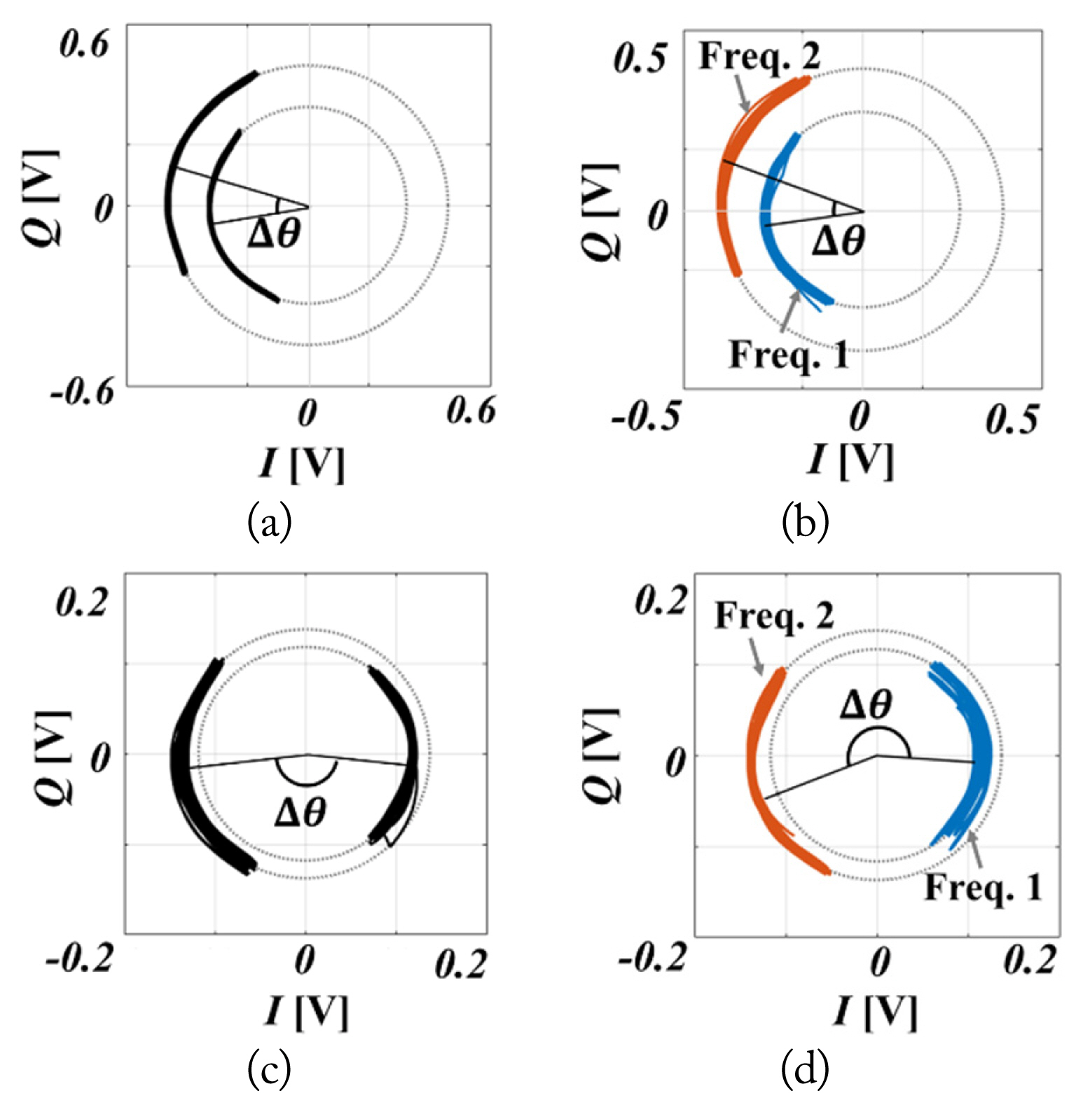
The measured phase differences ╬ö╬Ė denoted by ╬Ėf2ŌĆō╬Ėf1 at each distance are indicated on the complex plane. Fig. 7(a) and 7(b) shows the same value of ╬ö╬Ė at a distance where the value of ╬ö╬Ė is less than ŽĆ. However, distance measurements without frequency discrimination cannot be used within the distance where the value of ╬ö╬Ė is greater than ŽĆ, as shown in Fig. 7(c), owing to phase-difference selection. Fig. 7(d) shows that the distance of 1.7 m, where the value of ╬ö╬Ė is greater than ŽĆ, can be accurately measured by frequency discrimination using the proposed method.
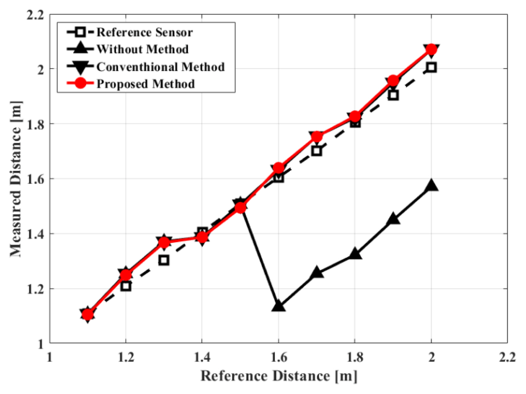
Fig. 8 shows the measured absolute distance detection, depending on the FSK radar frequency discrimination method used. The distance measurements made without applying any frequency discrimination method (labeled ŌĆ£Without MethodŌĆØ) always yielded a phase difference smaller than ŽĆ, between ╬Ė and 2ŽĆŌĆō╬Ė, to avoid phase-difference selection. FSK radar could only detect distances from 1.1 m to 1.5 m using a frequency spacing of 150 MHz, and distances longer than 1.5 m could not be distinguished due to the limited phase discrimination range. In contrast, FSK radar using conventional and proposed frequency discrimination methods measured a distance of up to 2 m without the ambiguity of the distance decision using a frequency spacing of 150 MHz. When distance detection using FSK radar was implemented without the frequency discrimination method, the measurement accuracy was reduced at a specific distance range, as shown in Fig. 8, owing to the incorrect selection of phase differences. FSK radars using frequency discrimination methods measured the distance up to the maximum unambiguous range corresponding to a phase difference of 2ŽĆ. The detection accuracies of FSK radar at distances of 1.1 m to 2.0 m were 97.56% using the synchronization signal and 97.08% using the proposed method.
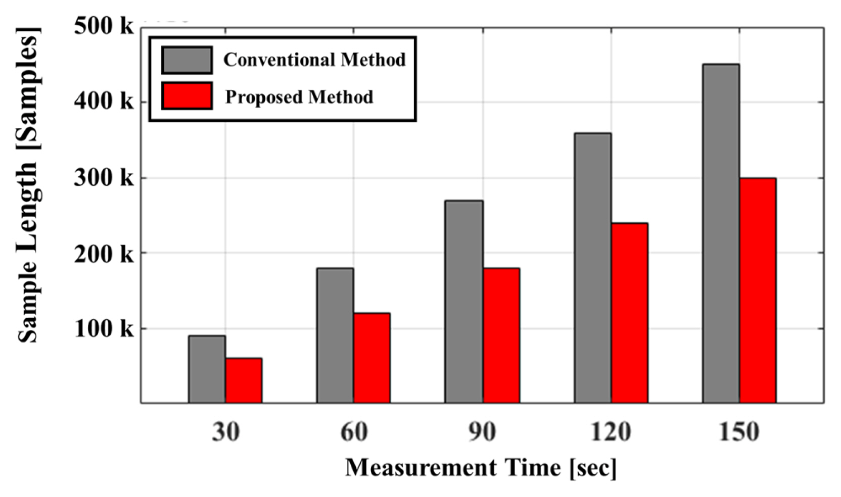
Fig. 9 shows the number of samples acquired using the conventional versus proposed methods. The conventional method requires the acquisition of a control signal for frequency discrimination. The number of samples of the control signal is half that of the baseband I/Q signals. The difference in the number of samples from the conventional method increases linearly in proportion to the measurement time. Acquiring the control signal is not necessary for the proposed method, as it can discriminate the baseband signal by frequency without synchronizing with the control signal. The number of samples for the proposed method was 0.66 times smaller than that for the conventional method. Table 1 shows the computation time for signal processing using the conventional vs. proposed methods for absolute distance measurement. The data were acquired at a sample rate of 1 kHz for 30 s, and the computation time was obtained by repeating the signal processing 120 times. The results show that the proposed method decreased the signal processing time by 44 ms compared to the conventional method. This improvement is attributed to eliminating the loop statement, which increases the computation time in signal processing.
IV. Conclusion
A frequency discrimination method using asymmetric transmission time is proposed as an alternative solution to the problem of phase-difference selection in FSK radar. The baseband signal for each frequency can be distinguished by comparing the number of samples after envelope detection owing to the transmitted signals with different durations. The frequency-specific phase differences for the distance measurement using FSK radar were obtained from the discriminated baseband signals using the proposed method. The problem of phase-difference selection does not affect the maximum unambiguous range, even without using control signals or specific measurement procedures. The proposed method can reduce the computation time in FSK radar signal processing by removing the need to use a control signal for frequency discrimination. The experimental results showed that the proposed method can efficiently calculate the absolute distance in signal processing using FSK radar up to the maximum unambiguous range corresponding to a 2ŽĆ phase difference while using 0.6 times less data than the conventional method.