I. Introduction
As new mobile devices continue to be miniaturized, antenna sizes continue to be reduced. To maintain a compact antenna design, achieving a wider bandwidth and higher efficiency has become a serious challenge for engineers. The most widely used antenna in mobile devices is the planar inverted-F antenna (PIFA), which adds a shorting line to the monopole antenna. The shorting line and the feed line form the feed structure used to adjust the coupling between the feed and the radiating element. However, PIFA makes it difficult to achieve the desired impedance bandwidth with limited dimensions [1]. In previous studies, a wideband technology called a planar inverted-E (PIE) feed structure was proposed. This technology uses PIFA by adding a shunt capacitor to the conventional feed structure, forming a parallel resonance feed structure. Using this technology, impedance bandwidth can be increased to 2ŌĆō3 times without changing the occupying space of the antenna [2ŌĆō7]. PIE technology can greatly increase the bandwidth of antennas. However, investigators have only conducted studies on impedance bandwidth extension and have not dealt with the issue of radiation efficiency in detail. Although the impedance bandwidth has been increased by 2ŌĆō3 times, it was observed that its efficiency characteristics were aggravated in some cases within the extended impedance bandwidth [8].
In this paper, we investigate the cause of the deterioration of efficiency in a circuit that uses a parallel feeding structure, such as a PIE antenna developed to obtain a wide impedance bandwidth, and propose a solution to this problem. Through several studies on the efficiency of PIE antennas, it has been observed that efficiency was reduced to null at a specific frequency, and the frequency was controlled by the dimension of the specific point of the PIE feeding structure. We analyzed the ŌĆ£efficiency null,ŌĆØ where the efficiency decreases to zero when using the PIE feed structure and proposed a method to improve the average efficiency of the antenna by controlling the efficiency null through the modification of the feed structure. Two PIE feeding structures were presented to compare the radiation efficiency changes according to the changes in the feeding structure shape. The ground plane, feed point, and radiating element of the two antennas are nearly the same. The difference lies in the size of the parallel resonance feed structure. By modifying the size of this feed structure, the frequency of the efficiency null can be controlled. Then, significant efficiency enhancement to the antenna operating band can be achieved, and the impedance bandwidth can also be improved. Simulation and experimental results verify the effect of the modified antenna performance improvement.
II. Antenna Design
The geometries of the two antennas are shown in Fig. 1. PCBs are manufactured using Frame Retardant 4 substrate (╔ør = 4.4, tan╬┤ = 0.02). Each antenna consists of the ground plane, a feed structure, and a radiating element. The size of the ground plane is 100 mm ├Ś 50 mm with a clearance of 20 mm ├Ś 50 mm for setup. The feed structure is a parallel resonator that includes a feed line, a shorting line, and a shunt capacitor line. The left-loop circuit in the feed structure includes the shorting line and the shunt capacitor line. Because of the distributed inductance and its lumped capacitance, the left-loop circuit is considered an LC-resonance circuit. The resonance frequency of this circuit is usually controlled near the operating frequency of the radiating element to achieve impedance bandwidth enhancement [9ŌĆō11]. Therefore, the size and value of the shunt capacitor of this loop remain the same in antenna 1 and antenna 2. The left-loop circuit measures 5.5 mm ├Ś 0.3 mm, where C1 = C2 = 8 pF. The right-loop circuit in the feed structure includes the shunt capacitor line and the feed line. It measures 5.5 mm ├Ś 3.2 mm for antenna 1, whereas it measures 1 mm ├Ś 3.2 mm for antenna 2.
III. Operating Mechanism
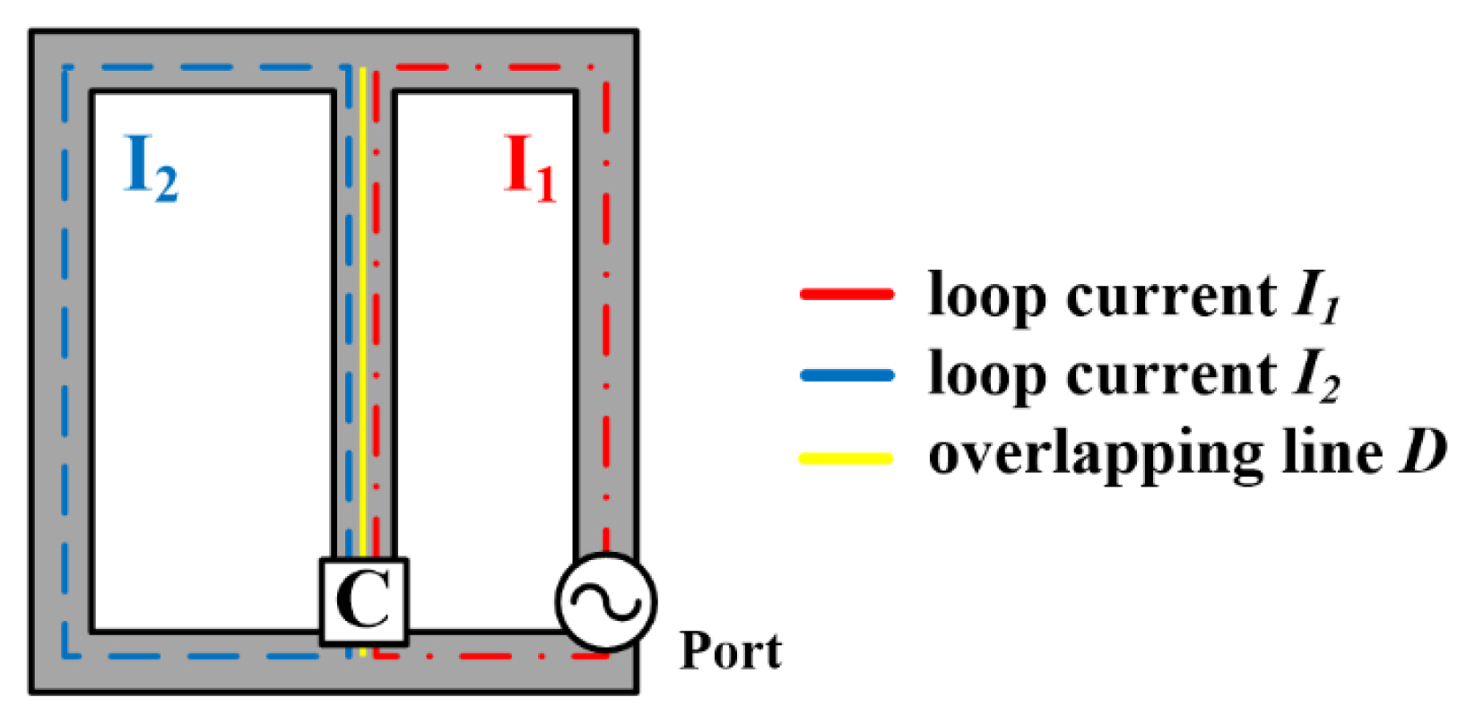
A diagrammatic sketch of the feed structure is shown in Fig. 2. When the current flows from the feed, it flows in the right-loop circuit, producing loop current I1. Next, it couples to the connected left-loop circuit to induce loop current I2. Energy is mainly delivered to the radiating element through the shorting line, as in conventional PIFA. Thus, in the PIFA, using PIE technology, RF energy is delivered from the feed to the circuits of I1 and I2, successively, and then to the radiating element. The overlapping part of the two loop circuits is recorded as D, determining the coupling between I1 and I2.
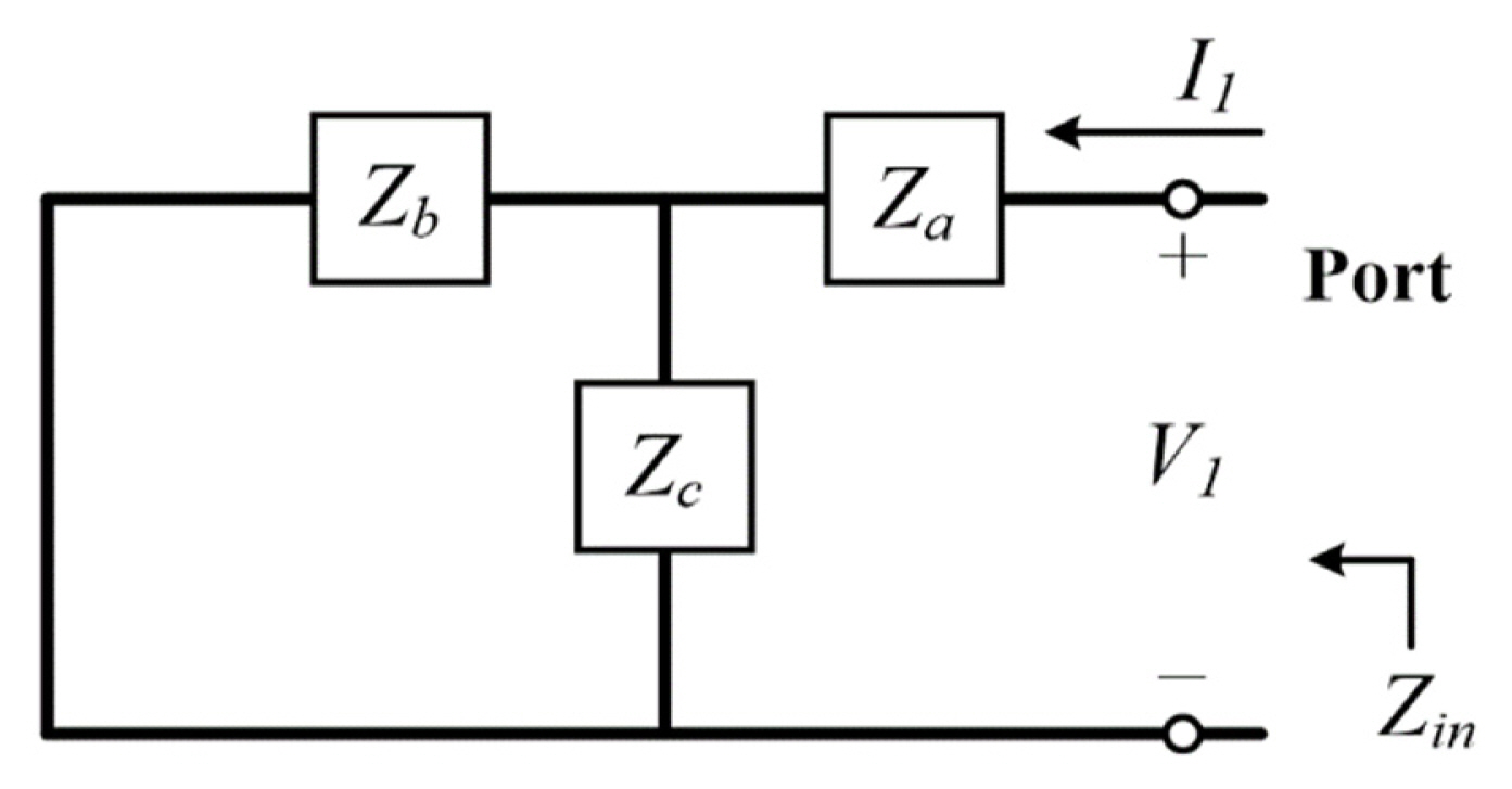
To prove this effect, the equivalent circuit of the feed structure is introduced, as shown in Fig. 3. The port represents the feed point [12]. Z elements are lumped elements representing the impedance on a circuit line. Za is determined by the right-loop circuit of the feed structure but excludes D. Zb is determined by the left-loop circuit of the feed structure but excludes D. Zc is determined by the distributed inductance and lumped capacitance of overlapping line D. Therefore, the voltage value on D can adjust the mutual coupling strength between I1 and I2 [13].
The distributed inductance and lumped capacitance on D can cause series LC resonance at specific frequencies. This is called ŌĆ£parasitic resonance.ŌĆØ At the frequency of parasitic resonance, Zc is zero, and the induced voltage on D is shorted to zero. Thus, I2 is not efficiently generated, and energy cannot be delivered to the radiating element. Therefore, an efficiency null is generated, accompanied by a narrowed bandwidth.
IV. Simulated and Measured Results
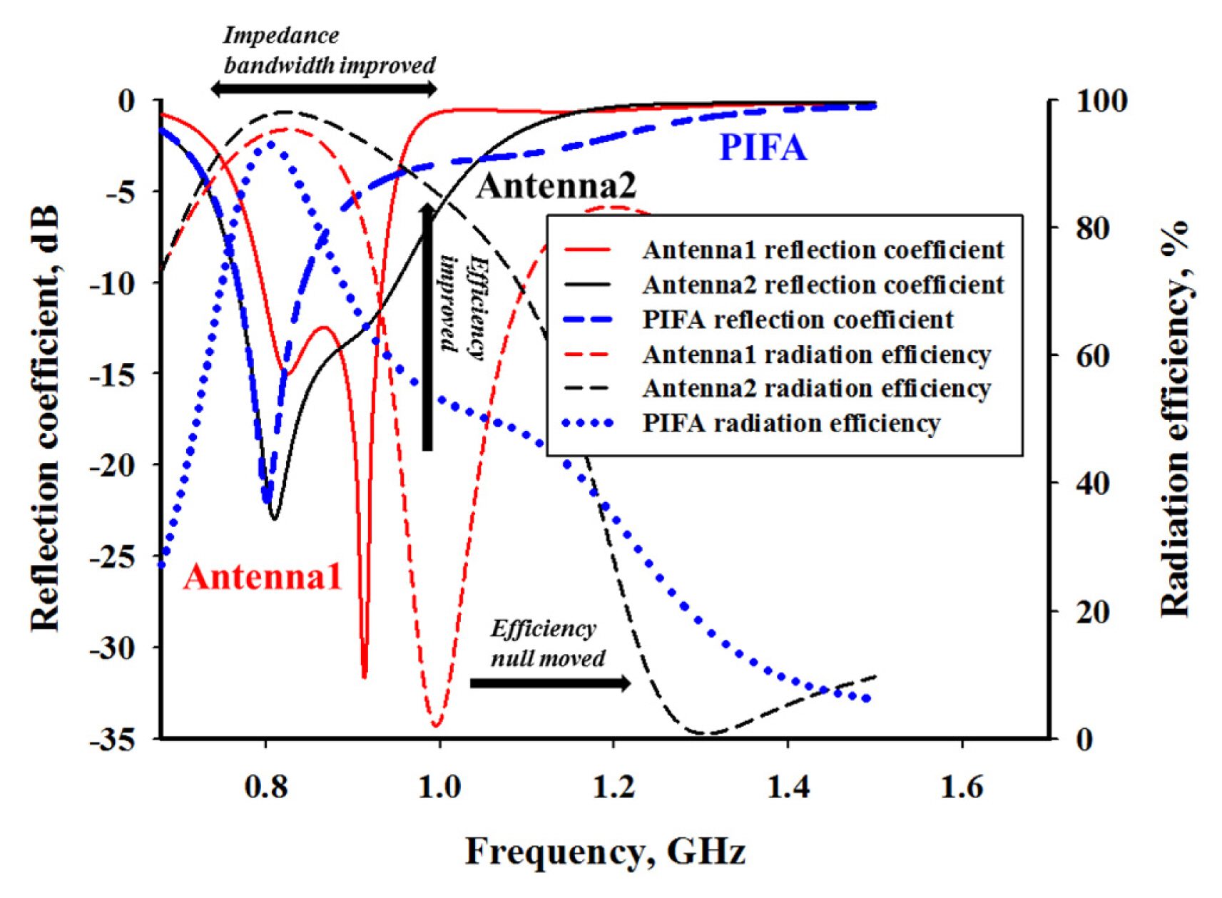
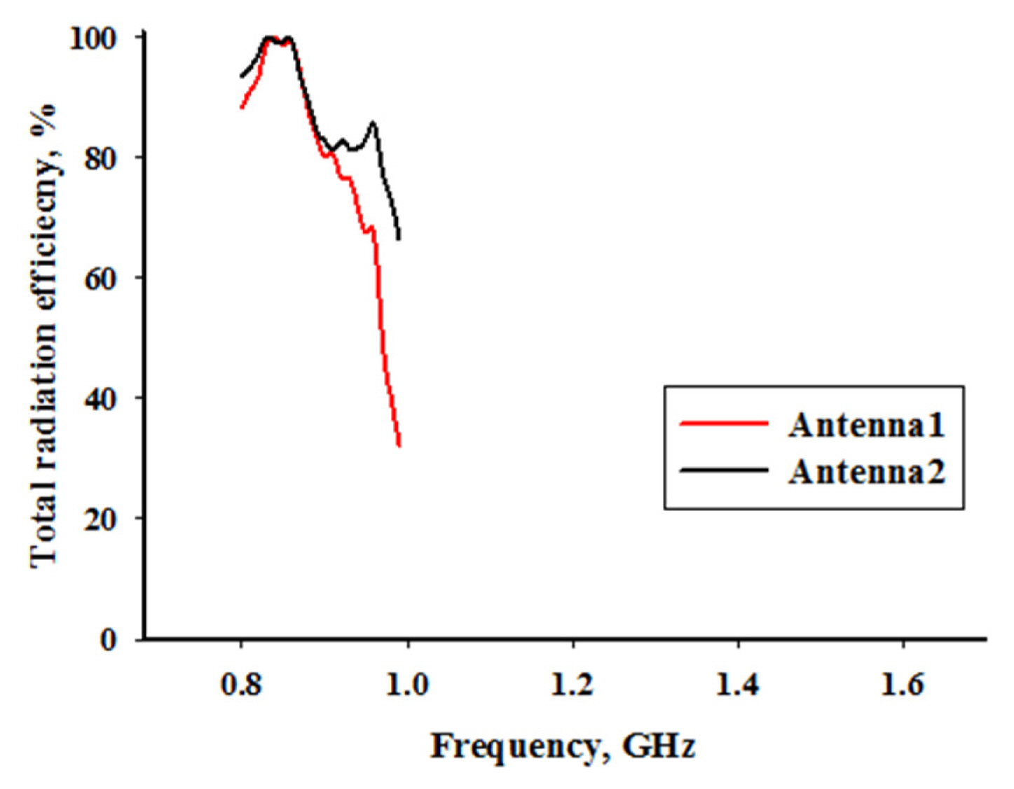
The simulated reflection coefficients and radiation efficiencies of the two considered antennas are shown in Fig. 4. The efficiency null of antenna 1 is generated at 1 GHz, and that of antenna 2 is shifted to 1.3 GHz. Because the efficiency null of antenna 1 is generated close to the antenna operating band, its efficiency is sharply reduced near 1 GHz. This causes the 3:1 voltage standing wave ratio (VSWR) bandwidth of antenna 1 to be reduced. The bandwidths of antennas 1 and 2 are 160 MHz and 240 MHz, respectivelyŌĆöa major difference. Fig. 5 shows the total efficiencies of the two antennas, including the reflection losses. The measured results are in good agreement with the simulation results. The efficiencies of the two antennas at 0.8ŌĆō0.9 GHz are roughly the same, but for 0.9ŌĆō1 GHz, the efficiency of antenna 2 is significantly higher than that of antenna 1. At 990 MHz, the efficiency values of the two antennas are 32% and 66%, respectively.
In the design of the feed structure of antenna 2, the height of the right-loop circuit is reduced. This subsequently leads to the distributed inductance generated on D being reduced. Because the shunt capacitor has not changed, the parasitic resonant frequency shifts.
V. Conclusion
The parallel resonance feed structure technology for PIFA was discussed in this paper. When the overlapping part of the two loop circuits of the feed structure resonated to the point of almost being shorted, the coupling between the feed and the feed structure turned to zero, causing an efficiency null at a parasitic resonance frequency. For the proposed antenna, the size of the feed structure was modified to increase the LC resonance frequency of the overlapping line. Because the parasitic resonance frequency was far from the antenna operating band, the efficiency and impedance bandwidth were enhanced. This research is of great significance to the design and application of high-performance compact antennas.