I. Introduction
With the advent of 5G communications, millimeter-wave (mm-wave) frequencies at Ka-band, which are allocated for high-band 5G use, have recently garnered considerable interest [1–3]. In addition, improved data rates provided by 5G technology have become a springboard for the development of Internet-of-Things (IoT) technology in various applications [4–6]. Improved data rates require higher energy consumption of battery-powered IoT devices, but compact IoT devices inevitably have a short battery lifetime due to battery-size limitations. To solve the battery problem of IoT devices in 5G wireless systems, far-field wireless power transfer (WPT) and RF energy harvesting have the potential as a means for supplying energy to compact, low-power devices using mm-waves [7–9].
In these WPT and energy harvesting scenarios, it is essential to design an optimal mm-wave receive antenna to efficiently collect electromagnetic waves [10, 11]. Although it is common for mm-wave antennas to be configured in an array due to their small physical size [12–14], arrays may still be too large for implementation on compact, low-power IoT devices with small footprints. For this reason, a compact single antenna with good radiation characteristics would be desirable for devices with a limited size. Moreover, a compact, single antenna has the advantage of being applied not only to IoT devices that make use of 5G communications but also to ultra-compact devices that do not need 5G capability but can still benefit from using compact antennas for energy harvesting. Various single antenna designs have been proposed in recent studies that can be utilized for mm-wave WPT and energy harvesting schemes [15–21]. In particular, a wideband mm-wave antenna has the advantage of being able to accommodate a wide range of mm-wave frequencies [16–21].
In this regard, a bowtie antenna with wideband characteristics can be a reasonable option, but an additional feeding structure, such as a balun, is required due to its dipole-based configuration. To compensate for this structural complexity, a self-complementary design can be applied to the bowtie antenna to simplify the feeding structure, thereby minimizing antenna size while maintaining a wide bandwidth [22, 23].
In this study, we propose a novel wideband directive self-complementary bowtie antenna (SCBA) that covers the entire Ka-band (26–40 GHz), which can be utilized as a single receive antenna for WPT and energy harvesting in compact devices. Unlike the conventional SCBA based on a design without a ground plane [23], the proposed SCBA design includes a ground plane to prevent unnecessary backward radiation, thereby enhancing directivity. Despite the presence of a ground plane that reduces bandwidth, the optimized design with a ground plane exhibits a wideband characteristic that covers the entire Ka-band. In other words, the proposed SCBA not only has enhanced gain through the ground plane but also maintains the wide bandwidth of the conventional SCBA. The proposed wideband directive SCBA is demonstrated via numerical simulation and measurement.
II. Wideband Self-Complementary Bowtie Design
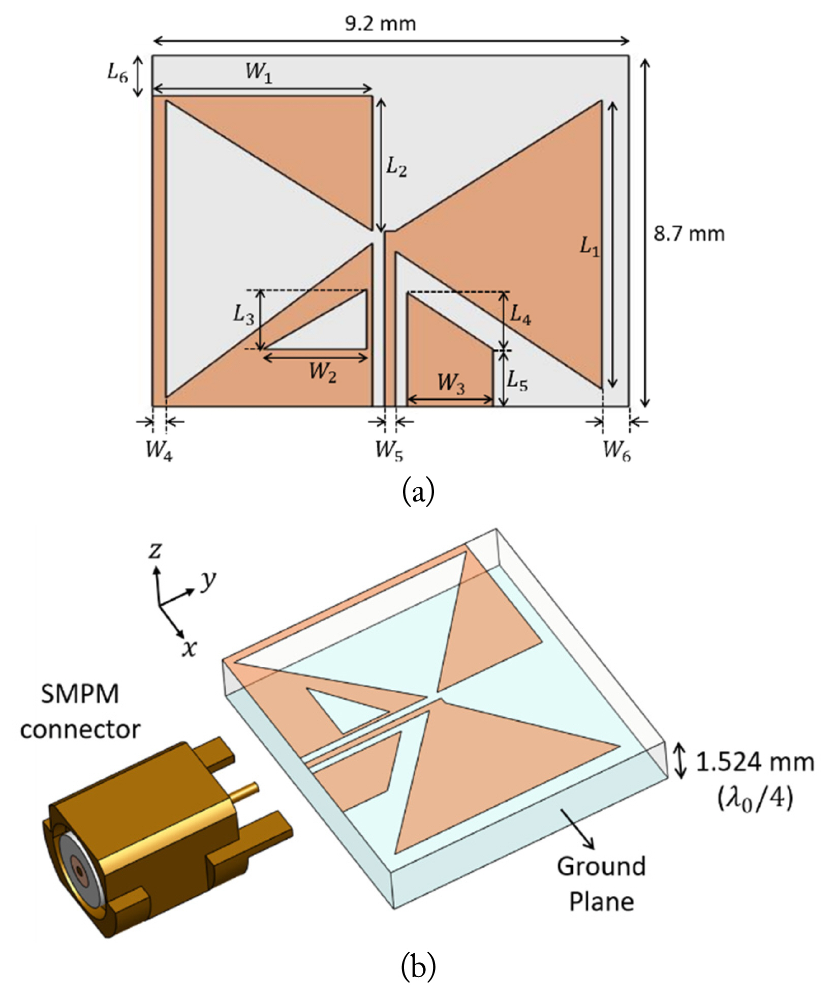
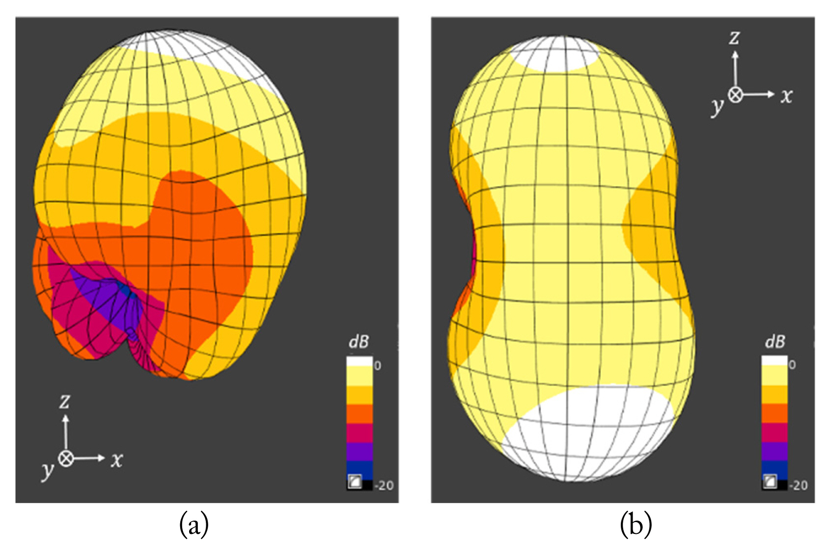
Fig. 1 illustrates the geometry of the proposed wideband SCBA. The SCBA consists of a bowtie-shaped structure with one conductive triangular patch and a complementary slot printed on the front side and a ground plane on the backside of the substrate. The patch and slot are symmetric with the same shape, forming the basis of a self-complementary structure. The substrate used in this design is a Rogers RT/Duroid 6002 laminate (ɛr = 2.94), which is known for low loss at high frequencies. The thickness of the substrate is chosen to be 1.524 mm, which is the standard thickness of the substrate that provides the best fit for our frequency band of interest. To elaborate, this allows us to set the ground plane distance to be a quarter wavelength at 28.7 GHz, which falls within the Ka-band. We then optimized the design parameters of the proposed SCBA to acquire a wide bandwidth. To accommodate the compact size of the SCBA, an SMPM connector is used as the coaxial feed. Using a compact coaxial feed connector should minimize its influence on the radiation pattern. The effect of the ground plane can be confirmed by comparing the radiation pattern of the SCBA with and without the ground plane. Fig. 2(a) and 2(b) show three-dimensional (3D) radiation patterns simulated at 28.5 GHz with and without the ground plane of the proposed SCBA, respectively. In the absence of a ground plane, the radiation pattern is visible as nearly symmetrical upward and downward, whereas in the presence of a ground plane, radiation occurs mostly in the upward direction. For this reason, the proposed design, which includes a ground plane, provides an enhanced gain compared to a conventional design.
As shown in Fig. 1(a), the feed line is in the form of a coplanar structure. The length and angle of the bowtie-shaped structure and the width of the center co-planar strip connected to the conductive patch are optimized for impedance matching. By adding an upper extra substrate region to the basic self-complementary structure, impedance matching at lower frequencies (below 27 GHz) is improved. A trapezoidal-shaped ground patch at the co-planar feed line improves impedance matching at higher frequencies (above 37 GHz). In addition, the triangular slot added at the co-planar feed line contributes to an enhanced broadside gain. As a result, the overall design is optimized to significantly improve the impedance bandwidth (IBW) and gain of the proposed SCBA in the Ka-band. The proposed SCBA has dimensions of 9.2 mm × 8.7 mm, and the optimized geometrical parameter values are listed in Fig. 1.
III. Measurement and Analysis
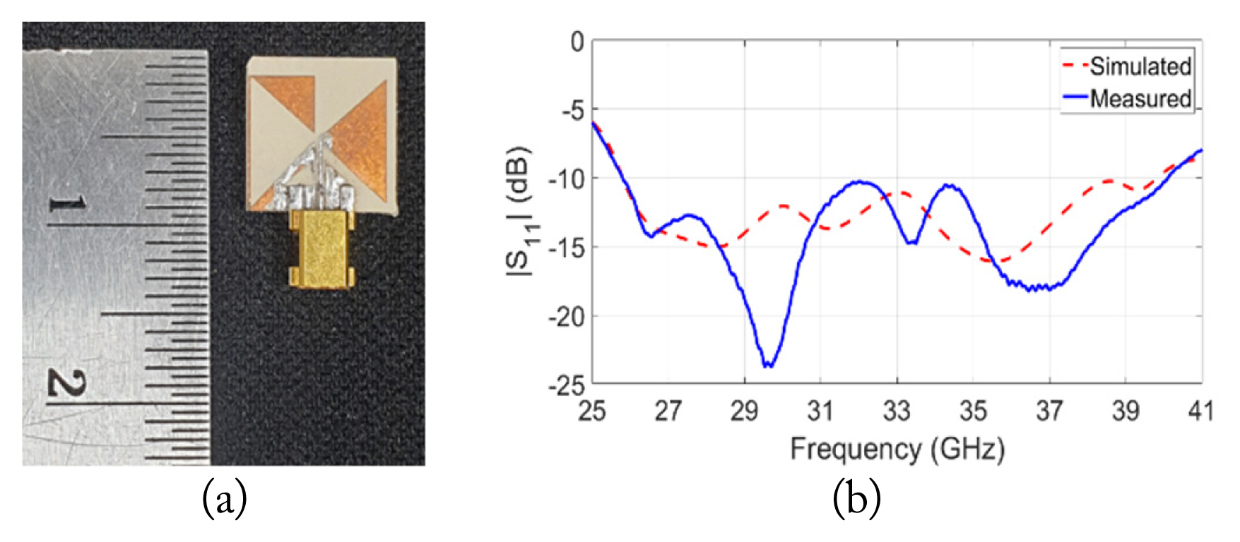
We tested the IBW of the proposed wideband SCBA via numerical simulation using SEMCAD X [24] and measurement using an Anritsu MS46122B vector network analyzer. As mentioned previously, the antenna was fabricated on a Rogers RT/Duroid 6002 substrate and connected with an SMPM connector (see Fig. 3(a)). In Fig. 3(b), the simulated and measured |S11| of the proposed SCBA are plotted. There is a reasonable agreement between the simulated and measured IBWs. The measured IBW (between −10 dB points) is about 43.4% (25.8–40.1 GHz), demonstrating that the proposed wideband SCBA covers the entire Ka-band.
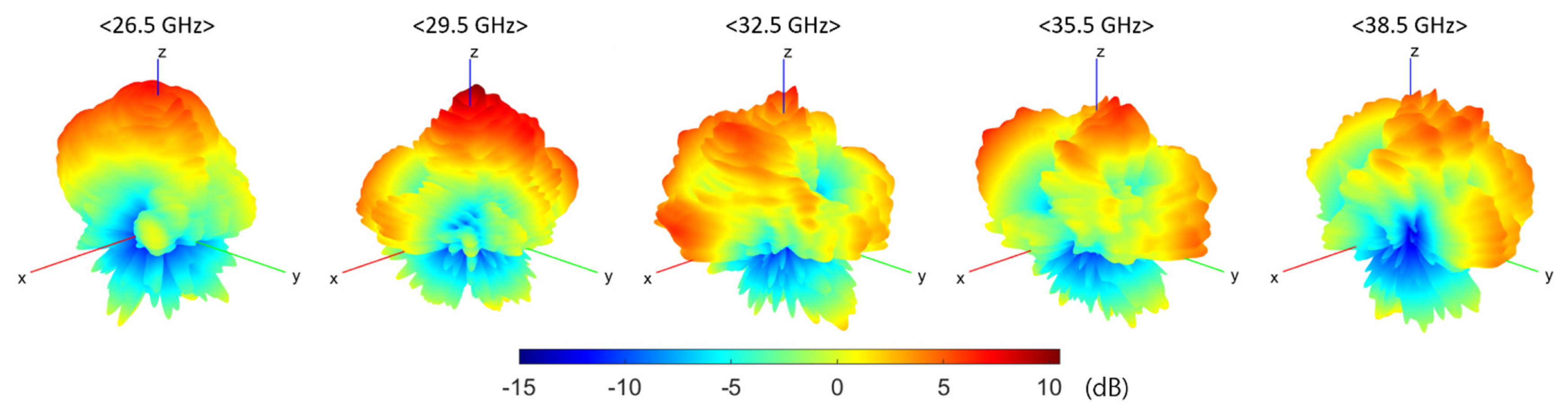
The radiation performance of the proposed wideband SCBA was also verified via simulation and measurement. The simulation was carried out using SEMCAD X, while the measurement was performed in an mm-wave spherical nearfield anechoic chamber, as shown in Fig. 4. Seven multiple dual-polarized probes inside the chamber measure a 3D nearfield pattern through mechanical and electronic omnidirectional scans. The near-field data are then transformed into far-field quantities to obtain radiation characteristics. From this measurement, full 3D co-polarized radiation patterns for five selected frequencies within the IBW of the antenna are obtained, as illustrated in Fig. 5. These results clearly show the effect of the ground plane on suppressing unnecessary radiation in the downward direction and, therefore, improving broadside gain as expected.
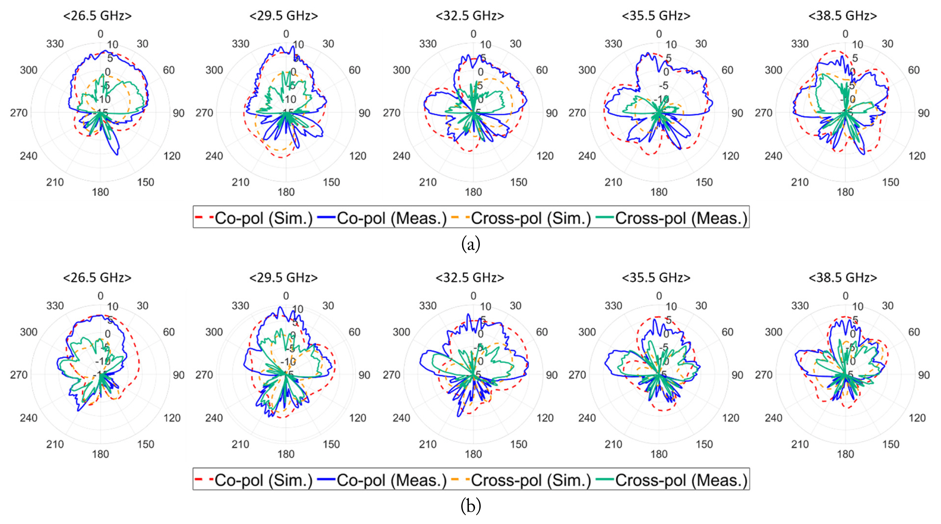
Fig. 6(a) and 6(b) show the simulated and measured radiation patterns for five selected frequencies, respectively, in the E− and H-plane (i.e., yz-plane and xz-plane in Fig. 5). There are some discrepancies between the simulated and measured co-polarized (co-pol) patterns, which are possibly attributed to an additional loss in the SMPM connector and substrate, and a misalignment of the antenna in the measurement setup. Nevertheless, the simulated and measured co-pol patterns, in general, exhibit good agreement in both the E− and H-plane. Although the main beam direction of the co-pol patterns in both the E− and H-plane tends to be slightly tilted at some frequencies, the broadside gain in the entire Ka-band belongs to the half-power beam-width of the main beam. Furthermore, it can be seen that the simulated and measured cross-polarized (cross-pol) radiation patterns maintain a significantly lower level compared to the co-pol patterns, where the difference in the broadside gain of the co-pol and cross-pol patterns is more than about −10 dB (up to −27.5 dB) at all five selected frequencies in both the E− and H-plane.
In Fig. 7, the maximum realized gain values at each discrete frequency point within the IBW are plotted, where the simulated and measured values also follow a similar trend with respect to each other. The peak simulated gain value of 9 dBi occurs at 28.5 GHz, while the peak measured value of 10.4 dBi occurs at 29.5 GHz. Note that the maximum gain values in Fig. 6 are obtained from the radiation patterns in the E− and/or H-plane, but if the antenna is not aligned perfectly, the actual maximum gain direction may deviate from the measured E− and/or H-plane patterns. Therefore, the gain measurement of the antenna can be further improved through a more precise antenna alignment and connection, which is a very delicate procedure, especially in the mm-wave frequency regime. The overall results demonstrate that the proposed SCBA design allows a wide IBW covering the entire Ka-band through an optimized design despite the presence of the ground plane; in addition, it provides a high broadside gain with improved directivity by pre-venting downward radiation.
Table 1 compares the performance of the proposed wideband SCBA with that of the ones in other recently reported works. For a reasonable comparison, only single-element antennas designed for frequency bands similar to this work are considered. The proposed wideband SCBA features the largest IBW covering the entire Ka-band and a relatively small electrical antenna size while maintaining the maximum gain as high as 10.4 dBi. In particular, the presence of a ground plane can be a more suitable choice when the antenna is used for a device-mounted application. Therefore, our proposed wideband SCBA has good potential for use in mm-wave WPT and energy harvesting scenarios for compact IoT devices.
IV. Conclusion
A novel wideband SCBA that covers the entire Ka-band with a ground plane for enhanced broadside gain was proposed and tested. By adding the ground plane and optimizing the antenna design accordingly, the proposed SCBA exhibits an IBW of 43.4% (from 25.8 to 40.1 GHz) and a maximum gain of 10.4 dBi at 29.5 GHz. The proposed design allows for high IBW with a small antenna size despite the presence of a ground plane; therefore, it is well suited for use in future mm-wave WPT and energy harvesting scenarios for compact devices, especially for device-mounted applications.