 |
 |
- Search
| J. Electromagn. Eng. Sci > Volume 22(3); 2022 > Article |
|
Abstract
Wireless power transfer (WPT) technology has been applied to fields as diverse as medical, electronic devices and transportation because of its convenience, safety and aesthetics. In particular, electric vehicles (EVs) that have emerged to replace internal combustion engines, which cause environmental pollution problems, are most suitable for applying WPT. Not only does convenience increase by eliminating charging cables, but the issue of heavy batteries can also be resolved by using dynamic WPT technology, which allows charging of batteries while driving. Furthermore, if dynamic WPT technology and autonomous driving technology are applied together to EVs, the driver’s convenience with regard to charging as well as driving will be greatly improved. In this paper, we propose a multi-purpose sensor coil system for use with dynamic WPT in an EV. Sensor coils detect any misalignment between the source coil and the load coil that occurs while the vehicle is being driven. Furthermore, the proposed system uses sensor coils and ferrite bars to transfer information, such as the lanes which vehicles are being driven. By transferring information, the proposed system can provide the benefits of autonomous driving technology as well as WPT technology. We theoretically analyze the proposed method and confirm that it can play two roles through simulations and experiments.
Wireless power transfer (WPT) is currently applied in various fields because of its convenience, safety, and aesthetics [1–5]. WPT technology is essential in the medical field for operations of human-implantable medical devices such as artificial organs. In addition, WPT technology has already been widely used in electronic devices such as mobile phones to eliminate the hassle of the cable connections for charging and damage to cable pins. In particular, the advantage of being able to charge objects without specific human behavior encourages research to apply WPT to more diverse fields.
Electric vehicles (EVs), which have emerged to solve environmental pollution problems and fossil fuel depletion problems, are among the most suitable systems in which to apply WPT. If WPT technology is applied to EVs, it can reduce the driver’s dependence on driving and charging along with autonomous driving technology. The SAE-J2954 regulation related to WPT for EVs has already been enacted, and some vehicle companies and universities have already developed and operated EVs with WPT [6].
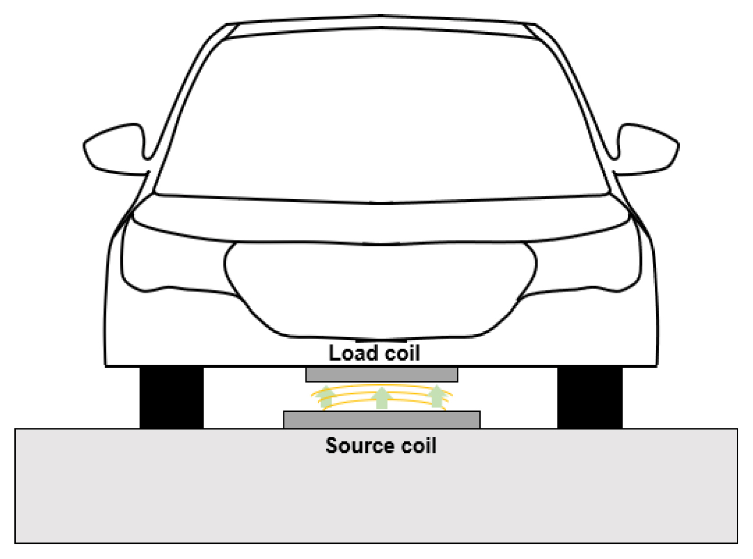
Among the various WPT methods currently available, the inductive power transfer (IPT) method is mainly applied to vehicles due to its small volume and high efficiency. The IPT method transfers power from a source coil to a load coil via a magnetic field [7]. As shown in Fig. 1, the IPT system applied to EVs has a source coil installed on the road and a load coil attached to the bottom of the vehicle. When the magnetic field from the source coil passes through the load coil, voltage is induced in the load coil. If the source coil and load coil are aligned correctly, as shown in Fig. 1, the induced voltage on the load coil reaches its highest level. However, if a misalignment occurs between the load coil and the source coil, the magnetic flux passing through the load coil decreases, resulting in a decrease in the induced voltage and a decrease in the power transfer efficiency [8]. Furthermore, the occurrence of misalignment exacerbates these type of electromagnetic field (EMF) problems due to leaks of the magnetic field.
Both static WPT, in which the vehicle is stopped and charged, and dynamic WPT, in which the vehicle is charged while driving, make it difficult for a person to align the vehicle with the source coil installed on the road. Therefore, the vehicles are equipped with assistive devices such as cameras, LIDAR (light detection and ranging) and GPS (global positioning system) to aid in alignment. These assistive devices have the disadvantage of not working properly in poor weather conditions and in places where satellite signals such as tunnels are not received, but they are essential devices in relation to autonomous driving technology, which requires considerable amounts of information for safe driving [9].
In this paper, we propose a method that detects misalignment between the source coil and the load coil using small sensor coils that work well even in the problem situations mentioned above and a method to transfer information that can augment autonomous driving. Specifically, we propose a method by which transfer the information essential for autonomous driving, such as the lanes in which vehicles are being driven, but which is thus far difficult to verify due to GPS errors.
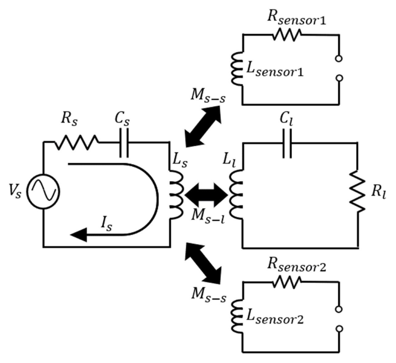
The sensor coil acts as a sensor with a small loop. As shown in Fig. 2, sensor coils are also affected by Faraday law, like a load coil, because they form a loop. The sensor coils for WPT systems have previously been proposed in other papers [10–15]. In one paper [10], the author proposed a method to detect lateral misalignment of the load coil using two sensor coils. The direction and magnitude of the misalignment were detected through the voltage difference induced on two sensor coils wound ahead of the load coil. In a paper published a few years later, a single sensor coil was used to detect lateral misalignment of the load coil [11]. In addition, unlike the previous studies, the sensor coils were also wound around the source coil rather than the load coil to confirm the location of a train [12]. The location of the train was determined by the voltage change that occurred in the sensor coil when the load coil attached to the train passed the source coil.
The main difference from the use of sensor coils in previous studies is the shape of the sensor coil and its role. In previous studies, the sensor coils were wound in the load coil or source coil, meaning that only a small amount of magnetic flux passes through the sensor coils. Therefore, in another paper [13], the author used an amplifier to check the induced voltage on the sensor coil. However, as shown in Fig. 3(a), the proposed system uses attached sensor coils with planes perpendicular to the magnetic flux to increase the induced voltage on the sensor coil. When comparing the previous sensor coil and the proposed sensor coil in a situation with an identical amount of inductance and same number of turns in a simulation, it was confirmed that the mutual inductance with the source coil was 60 times larger compared with when no misalignment occurred and at least 40 times larger when a misalignment occurred. In addition, the proposed sensor coil has the advantage of simply being attached to the existing load coil. In the proposed system, two sensor coils are attached under the load coil to detect misalignment and to receive information.
As mentioned in the introduction, a misalignment between the source coil and the load coil reduces the power transfer efficiency and causes EMF problems. Misalignment does not occur when a train travels along the rail, such as in a railway system, but misalignment must be considered when a vehicle travels along a road. Therefore, the proposed system can be applied to the dynamic WPT system of an EV. When no misalignment occurs, the sensor coil is symmetrically attached under the load coil, resulting in induced voltage at an identical magnitude. However, when a misalignment occurs to the left or right, the source coil and sensor coil are not symmetrical, resulting in induced voltage at different magnitudes on the two sensor coils. Therefore, the induced voltage on each sensor coil can be used to detect a misalignment of the vehicle in motion.
In this paper, sensor coils are used for information reception as well as for misalignment detection. The voltage induced in the sensor coils can be used to receive information from the source coil part to the load coil part. The amount of magnetic flux reaching the sensor coils can be adjusted using ferrite bars, which will be described in detail later in the paper. A small ferrite bar exists between the source coil and sensor coil and it reduces the magnetic flux transferred to the sensor coil, thereby reducing the induced voltage on the sensor coil. The number of ferrite bars determines the number of induced voltage reductions on the sensor coil, which can be used to transfer information. When applied to EVs, information about the lane in which the vehicle is currently being driven and about the driving environment can be transferred.
Voltage of the load coil and sensor coil is induced when the magnetic flux Φ from the source coil passes through the area of the load coil and sensor coil. The magnetic flux generated from the source coil can be determined as shown in Fig. 3, as follows:
Here, ℱ is the magnetomotive force, an ℛair and ℛferrite are the reluctance values of air and ferrite, respectively. In addition, the reluctance values of air and ferrite can be obtained as follows:
In these equations, lair is the air gap, lferrite is the height of the ferrite, μ0 and μ0μr are correspondingly the permeability of air and ferrite, and Sair and Sferrite are the cross-section area perpendicular to the flux of the air and the ferrite, respectively. According to (1)–(3), the two magnetic fluxes Φ1 and Φ2 are equal in the absence of a ferrite bar, resulting in the same magnitude of the voltage on the two sensor coils. However, if a ferrite bar exists between the source coil and sensor coil, the magnetic flux moves towards the ferrite bar with a low level of reluctance, as shown in Fig. 3(b) and Fig. 4(b). A ferrite bar can be used simply by positioning it in a system with a W-shaped source coil ferrite component [16]. Owing to the ferrite bar, the amount of magnetic flux passing through the sensor coil located above the ferrite bar decreases, which also reduces the induced voltage on the sensor coil. Because the width of the ferrite bar is as small as the size of the sensor coil, the voltage induced in the load coil decreases very little compared with that in the sensor coil. The equation below confirms that a small decrease in the induced voltage of the load coil does not cause a significant change in the mutual inductance between the source coil and load coil:
Here, ω is the operating frequency, Ms–l is the mutual inductance between the source coil and load coil, and Isource is the current of the source coil. Also, from the following WPT system efficiency equation, it can be seen that small changes in the mutual inductance do not significantly change power transfer efficiency:
In this equation, Rsource and Rload are the resistance values of the source coil and load coil, respectively. The efficiency does not change significantly because the decrease in the mutual inductance Ms–l is small. In other words, even if a small ferrite bar exists between the source coil and sensor coil for information transfer purpose, there is no significant change in the mutual inductance between the source coil and load coil, meaning that there is no significant decrease in power transfer efficiency. However, if it takes a long time to pass through the ferrite bar due to the slow speed of the moving load coil, a reduction in the efficiency can be further exasperated compared with when it quickly passes through.
A ferrite position identification (FPID) system, which uses ferrite to identify locations, was proposed in a previous study [13]. The system used FPID blocks to determine the location of a running train. Using the FPID block, this system changes the reluctance ℛ of (1)–(3) to generate higher magnetic flux Φ and higher induced voltage on the sensor coil. However, the system can generate higher magnetic flux Φ precisely to the target location (sensor coil) only in systems where no misalignment occurs, such as a train. In systems where misalignment occurs, such as a vehicle, the increased magnetic flux Φ does not reach the sensor coil, making the system inoperable. Furthermore, according to the EV wireless charging regulation SAE-J2954, there is no space to position FPID blocks due to large number of turns per layer of the source coil, and even if located, there is a limit to reducing the reluctance ℛ. However, the ferrite bar system proposed in this paper can play not only a role in information transfer but also a role in detecting misalignment even in systems where misalignment occurs, such as in vehicles. Furthermore, the proposed system simply positions a ferrite bar on top, meaning that even if the source coil for dynamic charging in the future has a large number of turns, as in the current static charging model of SAE-J2954, it can still be used.
The proposed system can play two roles. In sections where no ferrite bars exist, as shown in “section 1” in Fig. 5, sensor coils detect misalignment of a moving vehicle. When no misalignment occurs, voltage of the same magnitude is induced in the two sensor coils such that there is no significant difference. However, the magnitude of the voltage induced in the two sensor coils differs when misalignment occurs. The difference in the induced voltage in the two sensor coils can be used to determine not only whether a misalignment has occurred but also the direction of the misalignment. That is, as shown in Fig. 6, when the difference between the two induced voltages is zero, there is no misalignment, and the sign (+ or −) of the difference between the two induced voltages indicates the direction of the misalignment. Furthermore, the higher the voltage difference, the greater the misalignment from the center.
In sections where ferrite bars exist, indicated as “section 2” in Fig. 5, sensor coils receive information. As shown in Fig. 3(b) and Fig. 4(b), the magnetic flux moves to a ferrite bar with a low level of reluctance, hence reducing the magnetic flux reaching the sensor coil. As a result, the voltage induced in the sensor coil decreases when the sensor coil passes over the ferrite bar, as shown in Fig. 7(a). As shown in Fig. 5, when the load coil and sensor coils pass section 1 and enter section 2, and sensor coil No. 1 passes over the ferrite bar. Subsequently, sensor coil No. 2 passes over two ferrite bars, and section 2 ends as sensor coil No. 1 passes over the ferrite bar. As a result, as shown in Fig. 7(b), the magnitude of induced voltage on sensor coil No. 1 decreases first, after which the magnitude of induced voltage on sensor coil No. 2 decreases two times, with the magnitude of induced voltage on sensor coil No. 1 then decreasing again. The number of induced voltage reductions serves as important information. For example, if information is given to the vehicle about the lane in which the vehicle is being driven, the result in Fig. 7 can be interpreted as information indicating that the vehicle is currently driving in the second lane, because there are two induced voltage reductions in sensor coil No. 2 between the induced voltage reductions in sensor coil No. 1. If there is one ferrite bar passing through sensor coil No. 2, there will be one induced voltage reduction, which can be interpreted as the vehicle being in the first lane, whereas it is interpreted as being in the third lane if there are three ferrite bars. In addition to vehicle lane information, the induced voltage reduction can be recognized as a 0 (zero), allowing various forms of information, such as the current location, to be delivered in binary form.
In addition, even if the vehicles enter section 2 when misalignment is occurring, information is received. Due to the occurrence of the misalignment, only the reference voltage level that checks for a decrease in the voltage changes, with the reference voltage level determined based on the induced voltage in the sensor coil at the entry point.
Simulations were conducted to identify the two roles (misalignment detection and information transfer) of the proposed sensor coil system. The simulations were conducted using ANSYS Maxwell 3D, and the size of the load coil was designed to match the WPT3/Z2 dimension in accordance with the EV wireless charging regulation SAE-J2954. The dimensions of the air gap and operating frequency were also determined in accordance with SAE-J2954, and the dimensions of the source coil was designed only according to the width and thickness of the static charging source coil model in the SAE-J2954 regulation, because there is no model of dynamic charging. The dimensions and electrical parameters of the source coil, load coil, sensor coil, and ferrite bar are shown in Fig. 8 and Table 1.
The simulation is shown in Fig. 8(b), where the load coil and sensor coils pass through section 1, section 2, and section 1 again, in that order. Because the ferrite bar does not exist in section 1, the sensor coils detect a misalignment between the load coil and source coil, and in section 2, the ferrite bars are positioned to transfer information to the sensor coil. In section 2, the ferrite bars are located at 1,640 mm and 2,840 mm on the right side of the source coil and at 2,440 mm on the left side of the source coil.
During section 1 (0–1,640 mm and 2,840–5,800 mm), simulations were conducted for no misalignment and for 20 mm and 40 mm misalignment to the left and right, respectively. As mentioned earlier, if a misalignment occurs, it can be seen that the EMF problem is exacerbated in the direction of the occurrence of the misalignment, as shown in Fig. 9. Furthermore, as shown in Table 2, the mutual inductance between the source coil and load coil is reduced, leading to a reduction in the power transfer efficiency.
Sensor coils were used to solve those problems caused by a misalignment, and when no misalignment occurred, the sensor coils attached to both sides of the load coil were induced at the same voltage magnitude, indicating that the difference between the two induced voltages was zero, as shown in Fig. 10(a). However, if a misalignment occurs, the induced voltage difference between the two sensor coils is not zero, as shown in Fig. 10(b)–10(d). A comparison between Fig. 10(b) and 10(c) confirms that the phase of the induced voltage difference is opposite depending on the direction of the misalignment. In addition, a comparison between Fig. 10(c) and 10(d) shows that the larger the misalignment distance generated from the center is, the higher the induced voltage difference becomes. In other words, the voltage induced in the two sensor coils attached under the load coil can be used to determine the occurrence of a misalignment and the direction and magnitude of the misalignment.
In section 2 (1,640–2,840 mm), simulations were conducted to position the ferrite bars at a specific location and assess the possibility of information transfer. When the sensor coil passes over the ferrite bar, the path of the magnetic flux produced from the source coil is determined, as shown in Fig. 11. Unlike the right side of Fig. 11, a ferrite bar with low reluctance is located on the left side such that the magnetic flux moves through the ferrite bar. This reduces the magnetic flux passing through the sensor coil and the induced voltage every time it passes over the ferrite bar.
In the simulation, a ferrite bar is located 1,640 mm, 2,440 mm and 2,840 mm, as shown in Fig. 8(b). Sensor coil No. 2 attached to the right bottom of the load coil will pass through the ferrite bar at 1,640 mm and 2,840 mm points, while sensor coil No. 1 attached to the left bottom of the load coil will pass through the ferrite bar at 2,440 mm. As shown in Fig. 12, when the sensor coil passes over the ferrite bar, the magnitude of the induced voltage on the sensor coil decreases. In the case of sensor coil No. 1, one ferrite bar is located at 2,440 mm, so only the induced voltage on sensor coil No. 1 is reduced at 2,440 mm. Also, with regard to sensor coil No. 2, two ferrite bars are located at 1,640 mm and 2,840 mm such that the induced voltage in sensor coil No. 2 is reduced at 1,640 mm and 2,840 mm. Even when misalignment occurs, the reference voltage level changes, as shown in Fig. 12(c), but it can be seen that the induced voltage reduction for an information transfer still occurs. If the proposed system is used for lane recognition, this system will transfer information indicating that the vehicle’s driving lane is the first lane because the induced voltage reduction in sensor coil No. 1 occurred once between the induced voltage reductions in sensor coil No. 2. In addition, as the load coil passes over the ferrite bar, the mutual inductance between the source coil and load coil decrease by 3%, resulting in a 0.1% reduction in efficiency. Given these findings, it can be confirmed that information can be delivered without significant reduction in the efficiency.
Experiments were conducted to verify the operation of the proposed sensor coil system. The dimensions and electrical parameters of the source coil, load coil, sensor coil, air gap, and operating frequency used in the experiment are shown in Fig. 13 and Table 3. The experiments were conducted by downscaling to about a 1:2 ratio compared with the simulation model in Fig. 8. Also, simulations for the model that were downscaled to a 1:2 ratio were carried out, and these results are presented in Fig. 14.
As in the simulations, the load coil and sensor coils pass through section 1, where the ferrite bar does not exist, and then section 2, where the ferrite bars exist. In section 2 in the experiments, as shown in Fig. 13(d), the ferrite bars are located at 70 mm and 110 mm on the right side of the source coil and at 90 mm on the left side of the source coil.
The induced voltage difference between the two sensor coils when left and right misalignment occurs in section 1 is shown in Fig. 14(a) and 14(b), respectively. As in the simulation, the phase of the induced voltage difference between the two sensor coils is the opposite depending on the direction in which the misalignment occurs. Furthermore, the magnitude of the induced voltage difference is similar in the event of a misalignment at the same distance from the center. That is, the experiments show that two small sensor coils attached under both sides of the load coil detect the direction and magnitude of the misalignment.
The magnitudes of the induced voltage in sensor coil No. 1 and sensor coil No. 2 are shown in Fig. 14(c) and 14(d), respectively. Sensor coil No. 1 attached to the bottom left of the load coil passes the ferrite bar at 90 mm, thus reducing the induced voltage at 90 mm. Also, sensor coil No. 2 attached to the bottom right of the load coil passes the ferrite bar at 70 mm and 110 mm, thus reducing the induced voltage twice at 70 mm and 110 mm. In other words, as in the simulation, the experiments showed that when the sensor coil passes over the ferrite bar, the magnetic flux passing through the sensor coil decreases, hence reducing the induced voltage.
In this paper, we proposed a sensor coil system that can be applied to the dynamic WPT systems used in EVs to detect misalignment and transfer information. This system detects the directions and magnitude of misalignment through the induced voltage difference between two sensor coils. If the detected information aligns the load coil attached to the vehicle with the source coil installed on the road, this can reduce EMF problems while improving the WPT efficiency. Furthermore, small ferrite bars can also be used to reduce instantaneously the magnitude of the induced voltage on the sensor coils, which can transfer information from the source coil. This information can assist with the autonomous driving of the vehicle by transferring information about the lane in which the vehicle is currently being driven.
The proposed system was simulated with reference to SAE-J2954 and the experiment was conducted with 1:2 scaling. The simulations and experiments confirm that the proposed sensor coil system works well and that a system with a small sensor coil can play two roles, misalignment detection and information transfer.
Acknowledgments
This work was partly supported by Institute of Information & communications Technology Planning & Evaluation (IITP) grant funded by the Korea government (MSIT) (No. IITP-2020-0-00618, Development of commercialization technology for ultra small, high efficiency wireless charging for 1 kW class robot) and Basic Science Research Program through the National Research Foundation of Korea (NRF) funded by the Ministry of Science and ICT (No. NRF-2017R1A5A1015596). Also, we would like to acknowledge the technical support from ANSYS Korea.
Fig. 4
Side view of the proposed sensor coil system: (a) magnetic flux path without a ferrite bar and (b) magnetic flux path with a ferrite bar.

Fig. 3
Front view of the proposed sensor coil system: (a) magnetic flux path without a ferrite bar and (b) magnetic flux path with a ferrite bar.
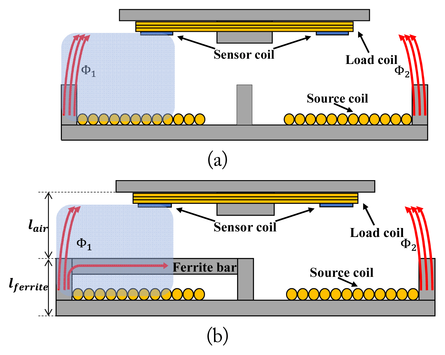
Fig. 5
Overall view of the proposed sensor coil system. Two sensor coils are attached to the bottom of the load coil. In section 1, sensor coils detect a misalignment between the source coil and the load coil. In section 2, some ferrite bars are positioned to transfer information and the sensor coils receive the information.

Fig. 6
Induced voltage difference between sensor coil No. 1 and sensor coil No. 2 depending on the direction and size of the misalignment.
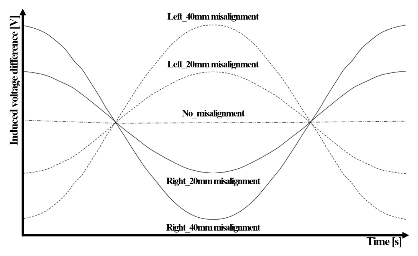
Fig. 7
Reduction of induced voltage on the sensor coil due to ferrite bar: (a) the induced voltage in the sensor coil decreases when passing through the ferrite bar and (b) variation of the induced voltage in two sensor coils over the distance in the situation shown in Fig. 5.
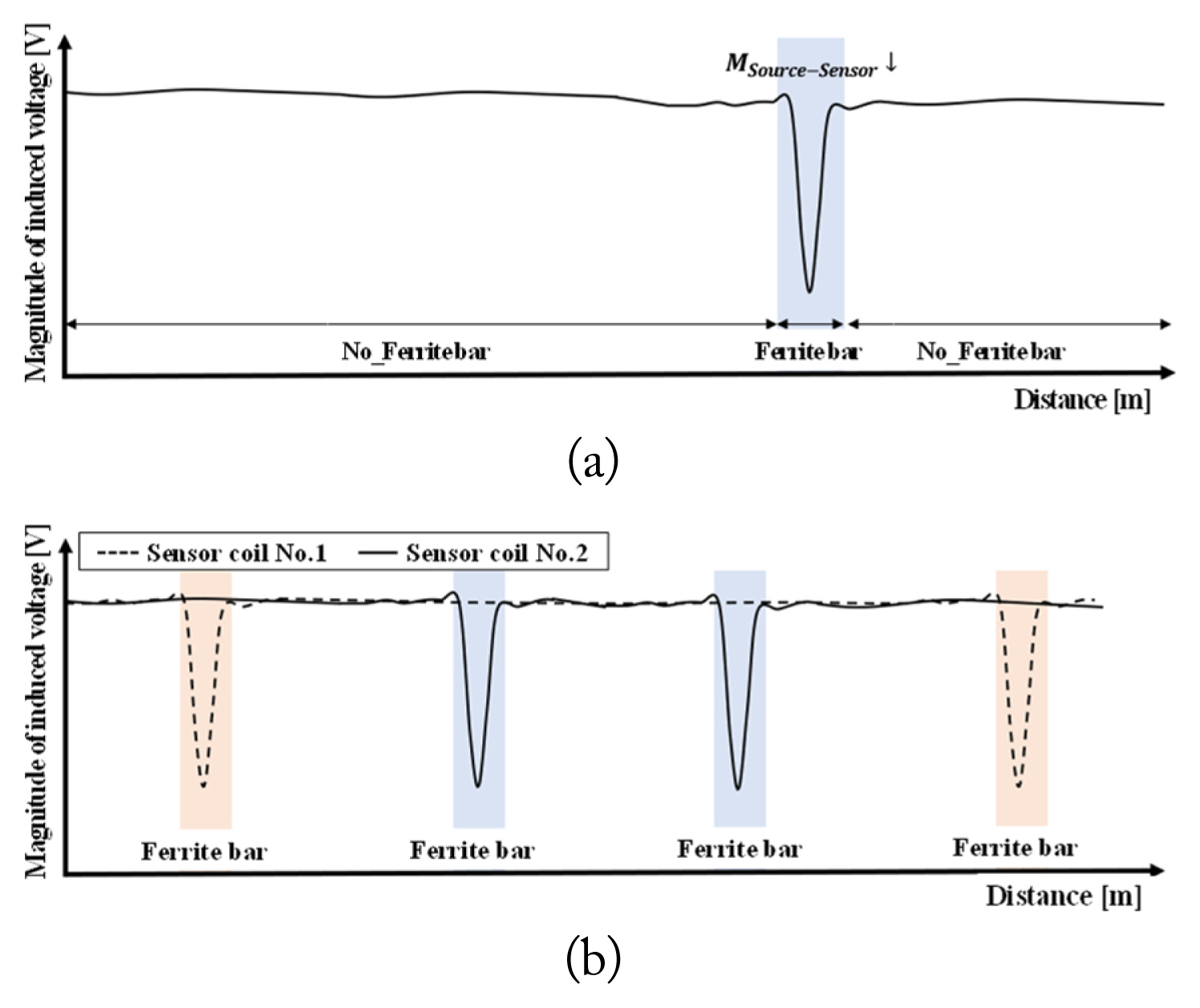
Fig. 8
Overall setup for the simulation: (a) front view of the simulation and (b) bird’s eye view of the simulation. The load coil and sensor coils move along the source coil, passing sections 1, 2, and then 1 again, in that order.
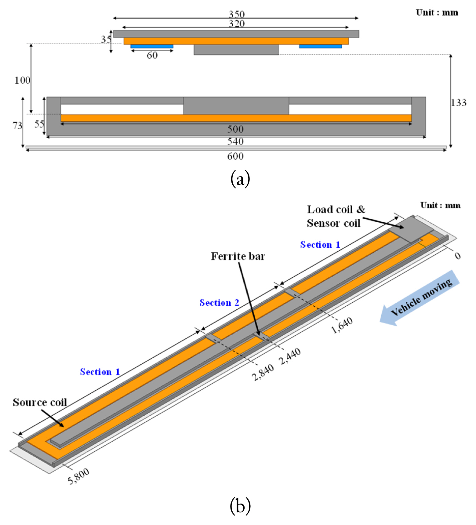
Fig. 9
Magnitude of the magnetic field from the source coil used in simulation. (a) When no misalignment occurs, a symmetrically small magnetic field occurs. (b) When a misalignment occurs, a very large magnetic field occurs in one direction. This exacerbates the EMF problem.
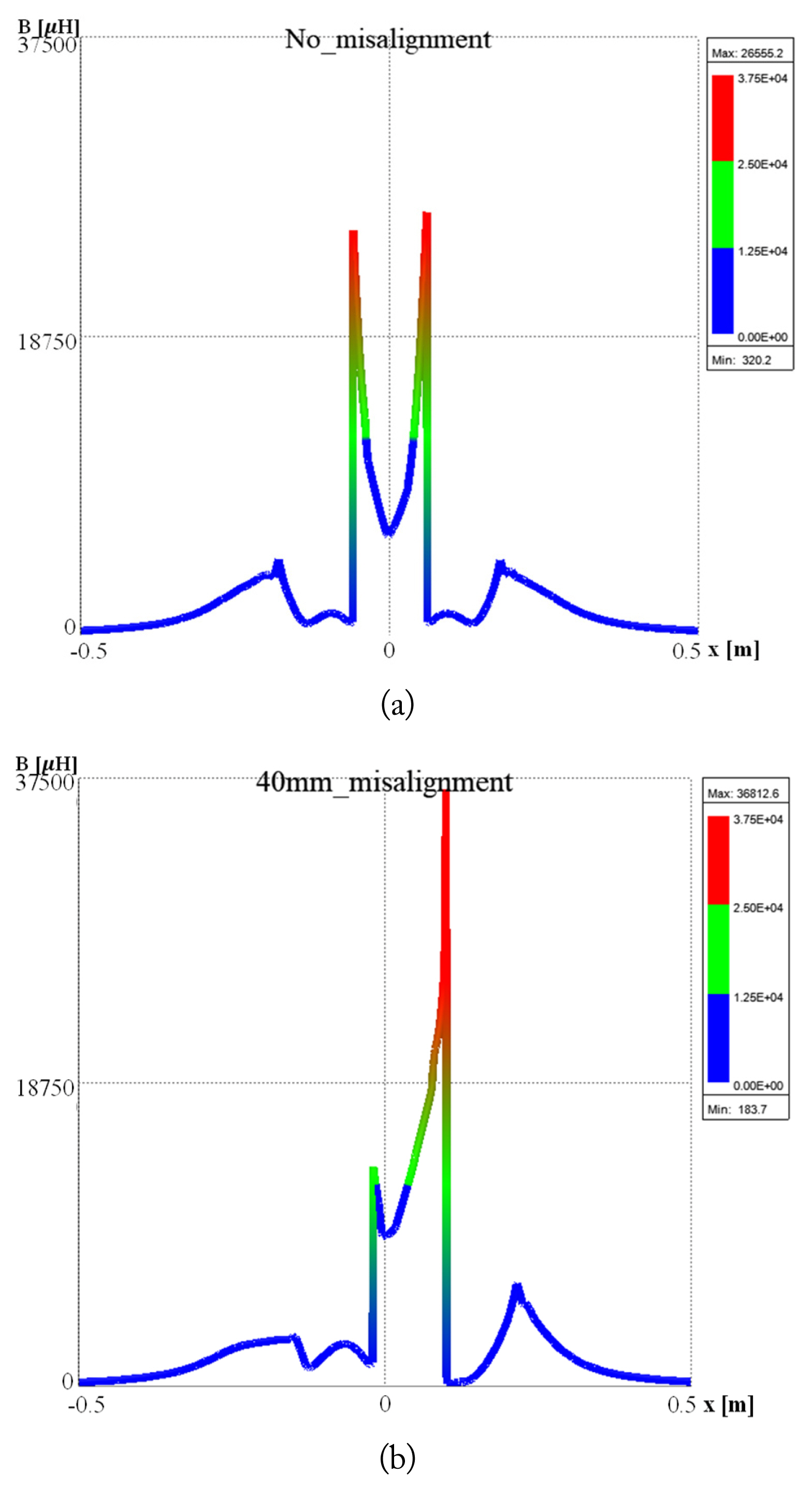
Fig. 10
Induced voltage difference between sensor coils. (a) When no misalignment occurs, the magnitude of induced voltage difference is almost zero. (b) When a left 20 mm misalignment occurs and (c) when a right 20 mm misalignment occurs. Here, (b) and (c) confirm that the phase of the induced voltage difference is opposite depending on the direction. (d) When a right 40 mm misalignment occurs, (c) and (d) confirm that the greater the distance away from the center, the greater the magnitude of the induced voltage difference.
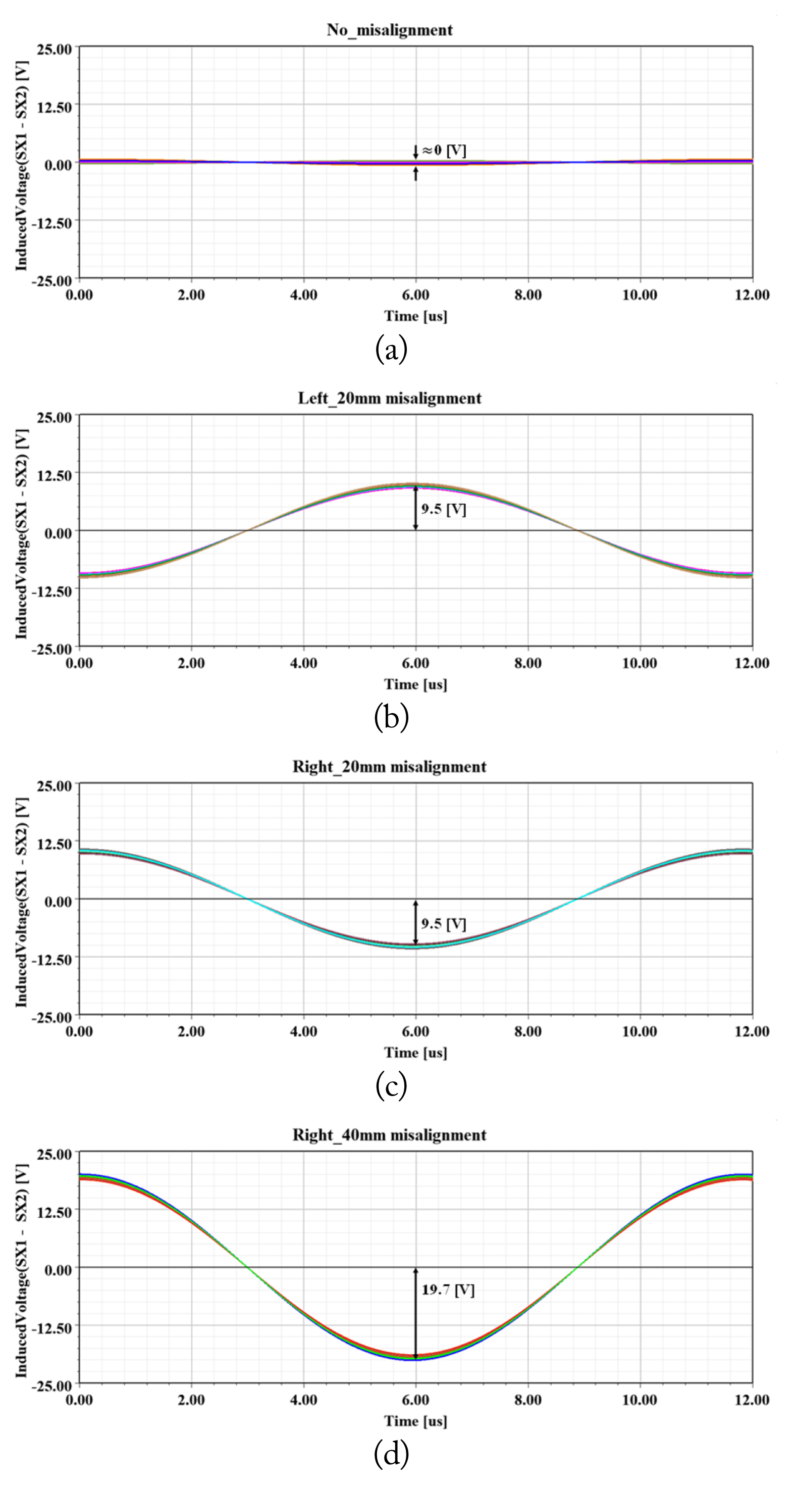
Fig. 12
Magnitude of the induced voltage in the sensor coils over certain distances. (a) In sensor coil No. 1, the induced voltage is reduced at 2,440 mm, where the ferrite bar is present. (b) In sensor coil No. 2, the induced voltage is reduced at 1,640 mm and 2,840 mm, where the ferrite bars are present. (c) In sensor coil No. 1, when a misalignment occurs, the induced voltage also is reduced at 2,440 mm.

Fig. 13
Experimental process: (a) experiment setup, (b) bottom view of the load coil and sensor coils, (c) section 1 for misalignment detection, and (d) section 2 for information transfer.
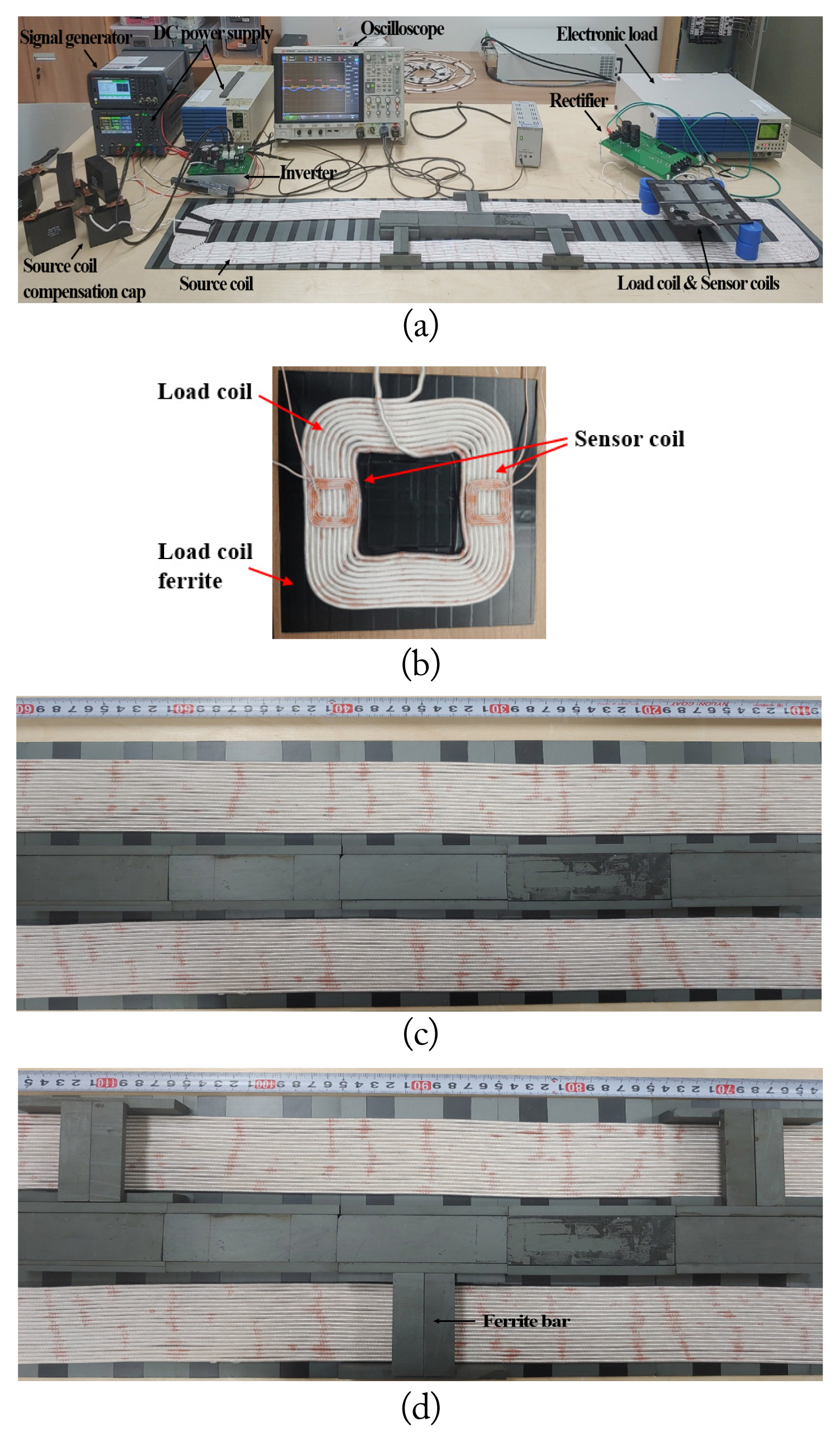
Fig. 14
Results of the experiment: (a) induced voltage difference when a left misalignment occurs, (b) induced voltage difference when a right misalignment occurs. (c) In sensor coil No. 1, the induced voltage is reduced at 90 mm where the ferrite bar is present. (d) In sensor coil No. 2, the induced voltage is reduced at 70 mm and 110 mm where the ferrite bars are present.
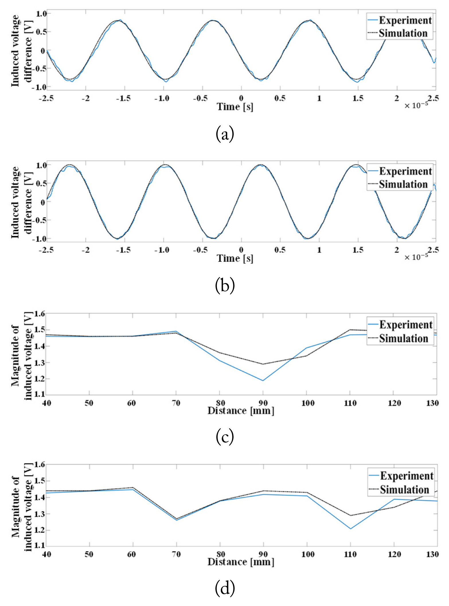
Table 1
Size and electrical parameters of source coil, load coil and sensor coil used in the simulation, and various parameters used in the simulation
Table 2
Mutual inductance change between the source coil and load coil due to a misalignment
| Case | Mutual inductance (μH) |
|---|---|
| No_misalignment | 148.3 |
| 20 mm_misalignment | 145.7 |
| 40 mm_misalignment | 139.1 |
Table 3
Size and electrical parameters of the source coil, load coil and sensor coil used in the experiment, and the various parameters used in the experiment
References
1. Z Zhang, H Pang, A Georgiadis, and C Cecati, "Wireless power transfer: an overview," IEEE Transactions on Industrial Electronics, vol. 66, no. 2, pp. 1044–1058, 2019.

2. J Park, J Kim, Y Shin, B Park, WS Kim, SJ Cheong, and S Ahn, "Toroidal-shaped coils for a wireless power transfer system for an unmanned aerial vehicle," Journal of Electromagnetic Engineering and Science, vol. 19, no. 1, pp. 48–55, 2019.


3. SH Hwang, CG Kang, SM Lee, and MQ Lee, "Reconfigurable wireless power transfer system for multiple receivers," Journal of Electromagnetic Engineering and Science, vol. 16, no. 4, pp. 199–205, 2016.

4. A Kurs, A Karalis, R Moffatt, JD Joannopoulos, P Fisher, and M Soljacic, "Wireless power transfer via strongly coupled magnetic resonances," Science, vol. 317, no. 5834, pp. 83–86, 2007.


5. H Arai, "Wireless power transfer system," Journal of the Korean Institute of Electromagnetic Engineering and Science, vol. 11, no. 3, pp. 143–146, 2011.

6. S Ahn, Y Chun, DH Cho, and J Kim, "Wireless power transfer technology in on-line electric vehicle," Journal of the Korean Institute of Electromagnetic Engineering and Science, vol. 11, no. 3, pp. 174–177, 2011.

7. GA Covic and JT Boys, "Inductive power transfer," Proceedings of the IEEE, vol. 101, no. 6, pp. 1276–1289, 2013.

8. V Prasanth and P Bauer, "Distributed IPT systems for dynamic powering: misalignment analysis," IEEE Transactions on Industrial Electronics, vol. 61, no. 11, pp. 6013–6021, 2014.

9. K Banerjee, D Notz, J Windelen, S Gavarraju, and M He, "Online camera LiDAR fusion and object detection on hybrid data for autonomous driving," In: Proceedings of 2018 IEEE Intelligent Vehicles Symposium (IV); Changshu, China. 2018, pp 1632–1638.

10. K Hwang, J Park, D Kim, HH Park, JH Kwon, SI Kwak, and S Ahn, "Autonomous coil alignment system using fuzzy steering control for electric vehicles with dynamic wireless charging," Mathematical Problems in Engineering, vol. 2015. article no. 205285. https://doi.org/10.1155/2015/205285


11. K Hwang, J Cho, D Kim, J Park, JH Kwon, SI Kwak, HH Park, and S Ahn, "An autonomous coil alignment system for the dynamic wireless charging of electric vehicles to minimize lateral misalignment," Energies, vol. 10, no. 3, article no. 315, 2017.
https://doi.org/10.3390/en10030315

12. K Hwang, D Kim, D Har, and S Ahn, "Pickup coil counter for detecting the presence of trains operated by wireless power transfer," IEEE Sensors Journal, vol. 17, no. 22, pp. 7526–7532, 2017.

13. K Hwang, J Cho, J Park, D Har, and S Ahn, "Ferrite position identification system operating with wireless power transfer for intelligent train position detection," IEEE Transactions on Intelligent Transportation Systems, vol. 20, no. 1, pp. 374–382, 2019.

14. Y Shin, K Hwang, J Park, D Kim, and S Ahn, "Precise vehicle location detection method using a wireless power transfer (WPT) system," IEEE Transactions on Vehicular Technology, vol. 68, no. 2, pp. 1167–1177, 2019.

Biography

Seokhyeon Son received his B.S. degree in electronic engineering from Kyungpook National University, Daegu, Korea, in 2020 and his M.S. degree from the Korea Advanced Institute of Science and Technology (KAIST), Daejeon, Korea, in 2022. He is currently a research engineer at Hyundai Motor Company. His research interests include wireless power transfer and electromagnetic compatibility.
Biography

Yujun Shin received his B.S. degree in electrical engineering from Inha University, Incheon, Korea, in 2016 and his M.S. degree from the Korea Advanced Institute of Science and Technology (KAIST), Daejeon, Korea, in 2018. He is currently completing his Ph.D. degree at KAIST. His research interests include wireless power transfer and electromagnetic compatibility.
Biography

Seongho Woo received his B.S. degree in electrical engineering from Kyungpook National University, Daegu, Korea, in 2019 and his M.S. degree from the Korea Advanced Institute of Science and Technology (KAIST), Daejeon, Korea, in 2021. He is currently completing his Ph.D. degree at KAIST. His research interests include electromagnetic interference and wireless power transfer.
Biography

Seungyoung Ahn received his B.S., M.S., and Ph.D. degrees at the Korea Advanced Institute of Science and Technology (KAIST), Daejeon, Korea, in 1998, 2000, and 2005, respectively. He is currently a professor at KAIST. His research interests include wireless power transfer system design and electromagnetic compatibility design for electric vehicles and high-mperformance digital systems.
- TOOLS


