I. Introduction
The fifth-generation (5G) network has been being rolled out and has exhibited a remarkable performance, such as a higher data rate, larger network capacity, lower latency, and ubiquitous mobile coverage, compared to its predecessors [1]; however, the exponential growth in data usage demand and the number of wireless devices creates new challenges for the 5G network as well as the next-generation networks [2]; especially, in the era of Internet of Things (IoT), this problem becomes more critical. Numerous technical efforts have been done for enlarging the network’s capability and enhancing the quality of service toward advanced communication applications. For instance, massive multiple-input-multiple-output (MIMO) technology, which uses a large number of antennas to achieve higher coverage and capacity, was introduced. A large millimeter-wave (mmWave) spectrum band is exploited to allow high-speed connectives and high network capacity. Moreover, non-orthogonal multiple access (NOMA), which uses a power-domain multiplexing technique to accommodate several users within an orthogonal resource block, showed a significant improvement in spectrum efficiency [3].
Recently, the intelligent reflecting surface (IRS), which is capable of reflecting electromagnetic waves with a controllable phase-shift and direction, has emerged as a promising technique to realize a smart and programmable wireless environment [4]. The key idea of the IRS is based on special electromagnetic properties on repetitive artificial subwavelength structures [5]. For convenience in manufacturing and deployment, the IRS consists of a large number of independent reflecting tiles (RTs) that are interconnected and controlled by a programmable controller. To verify the advantages of the IRS, the performance of IRS-aided wireless systems has been studied. The works on IRS’s physical channel modeling and channel estimation were done in [6–8], allowing for a performance evaluation of IRS-aided communication systems. In [9–12], the authors proposed potential applications of the IRS in various communication systems, such as wireless powered networks, secure communications, terahertz communications, cognitive radio systems, and MIMO systems, and showed that these systems gain a significant improvement in performance.
In this paper, we study the advantages of the IRS on enhancing performance of a practical indoor NOMA communication with imperfect successive-interference-cancellation (SIC) and in the presence of phase distortion (PD) caused by a non-ideal IRS. Unlike other approaches, where extravagant state variations are required at the IRS, our approach evaluates average performance metrics, i.e., the average achievable rates (AARs) at users, to significantly reduce IRS’s state variations, hence achieving robust power efficiency. First, we adopt a novel channel model proposed for indoor IRS-aided wireless communications in [10] to derive the signal-to-interference-plus-noise ratios (SINRs) for each signal at each user. Next, we study the distribution characterization of relevant performance metrics. Finally, the theoretical AAR formulas can be obtained using the above results. Numerical results are presented for analysis verification and performance evaluation. Moreover, these results point out the effects of system parameters, such as source transmit power, NOMA power allocation (PA) factors, RT allocation, the PD factor, and the SIC imperfection factor, on system performance.
The rest of this paper is organized as follows. The system and channel models are described in Section II. The SINR’s distribution and theoretical AAR formulas are studied in Section III. Numerical results and discussions are presented in Section IV. Finally, conclusions are presented in Section V.
 is the expectation of a random variable (RV) X.
II. System and Channel Models
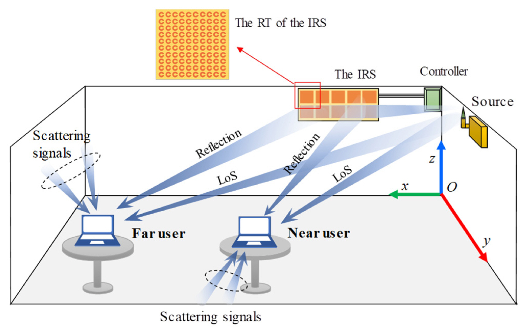
We consider an IRS-aided NOMA communication, as illustrated in Fig. 1, in which a source S communicates with two users, a near user U1 and a far user U2, with the help of an IRS attached to a wall. All nodes are single-antenna devices. The NOMA technique is used for data transmission for the users. The IRS includes N RTs, Rn, n = 1,…, N, and each RT is a reconfigurable metasurface and can independently direct the signal to a user under the control of a programmable controller. The channel model proposed for indoor IRS-aided wireless communications in [10, 13] is adopted to characterize the wireless channels of our system. For instance, the received signal at Um, m ∈ 1, 2, comprises of (i) the signals propagating over the line-of-sight (LoS) (or the direct link) and reflecting links, both are the dominant links, and (ii) scattering signals caused by multi-path fading or multiple reflections on the IRS. Let ℛm be the set of RTs allocated to Um, m = {1, 2}; hence, the channel between S and Um is expressed as
where
h m LoS h SR n U m Ref h m Fad ~ C N ( 0 , δ F a d 2 )
Let GS(θ, φ) and GUm(θ, φ), respectively denote directivity patterns of the transmit antenna of S and the receive antenna of Um where θ and φ are respectively the zenith and azimuth angles. For given locations of S and Um and given antenna’s orientations, we can calculate the values for θ and φ, hence obtaining the values for transmit/receive directivities for wireless links. Let
G S S → X ≜ G S ( θ X , φ X ) G U m Y → U m ≜ G U m ( θ Y , φ Y ) h m LoS h SR n U m Ref
where
λ 0 4 π d S U m λ 0 4 π d S R n U m ϕ SU m - 2 π d SU m λ 0 ϕ SU n U m = 2 π d SR n U m λ 0
As shown in (1), hm is a Rice distributed RV. Let h ~ Rice(Ω, K) be a general Rice distributed RV, then the cumulative distribution function (CDF) of |h|2 is expressed as [10]:
where
μ = σ Fad - 2 B k = ( 1 - e - K ∑ i = 0 k - 1 K i i ! ) / k !
Next, we study the effect of PD caused by non-ideal RTs on the received signal at the users. Regarding the NOMA principle, S transmits a combined signal
x S = α 1 x 1 + α 1 x 2 κ R n PD ~ CN ( 0 , τ R n P 0 )
where nm ~ CN(0, N0) is the additive white Gaussian noise (AWGN) at the receive antenna, and
x ^ s ≜ x s 1 - τ R n + κ R n PD 1 - τ R n  , or equivalently, the IRS does not add any power to the reflected signal. We can rewrite (5) as
, or equivalently, the IRS does not add any power to the reflected signal. We can rewrite (5) asIt is seen from (6) that ĥm ~ Rice(Ω̂m, K̂m) is still a Rice distributed RV, and
n ^ m ~ CN ( 0 , N 0 + σ PD 2 ) σ PD 2
The phase shift of each RT, i.e., ϕRn, plays an important role in system performance. It defines whether the received signals at Um via the dominant links are constructive or destructive. Let us consider the distance-propagation phase shift of the LoS link, i.e, ϕSUm, as the standard reference in the phase shift at Um, the signal-combining phase shift denoted by
ϕ R n s c ϕ R n s c
Using
ϕ R n s c h m Fad h m LoS h SR n U m Ref
(8)
Then, using the fact that the sum of independent complex Gaussian RVs is a complex Gaussian RV with its variance being the sum of all variances, we can calculate
σ PD 2
III. SINR Distribution Characterization and Average Achievable Rate Analysis
For convenience in analyzing the SINRs, we rewrite (5) as
According to the SIC principle of NOMA, the SINRs for the signal x2 at both users, i.e., Um, m = {1, 2}, are given by
where
γ m = P 0 / ( N 0 + σ PD , m 2 )
Using Shannon’s law, we can calculate the achievable rates (also known as the ergodic capacities) in bits/s/Hz for the signal x2 at both users as
and for the signal x1 at U1 as
where Y = min(Y1, Y2) is the condition for guaranteeing successfully decoding x2 at both users (note that U1 must decode x2 before decoding its information x1), and g ~ CN (0, λImSIC) in (13) represents the residual signal of x2 caused by the imperfect SIC receiver at U1 with variance λSICIm = ζE{|hSU1|2} and the SIC imperfection factor ζ ≤ 1.
Proposition 1
The CDF of X denoted by FX(t) = Pr(X < t) is approximated as
where ρm = μ/(α1γm), and η = λImSICα1/(μα2).
Proof
The approximate CDF of X is calculated as FX(t) ≈ Pr(|ĥ1|2 < (1 + γ1 |g|2 α2)t/(γ1α1)). Using the probability density function (PDF) of the exponential distribution given by f|g|2 (t) = λImSIC exp (−λImSICt)and (4), we obtain FX(t) via solving the following equation.
Proposition 2
The CDF of Y denoted by FY(t) = Pr(Y < t) is equal to one if t > α2/α1, and otherwise, it is calculated as
Proposition 3
The theoretical AAR expressions for the signals x1 and x2 are respectively given in the equations (19) and (20) shown in the top of the next page, where
C k = ∑ q = 0 k B 1 , q B 2 , k - q ( γ 1 ) - q ( γ 2 ) - k + q
IV. Numerical Results and Discussion
In this section, we present the numerical results for the AAR and discuss the effect of different key parameters on it. The theoretical results are derived for a general system, such as any type of transmit/receive directivity of the device antennas, frequency, wireless indoor environment, and device locations. For the simulation, we chose a specific setup for our system. Without loss of generality, we set the phase shifts of the IRS as ϕRn = 2π × mod(dSRn + dRnUm – dSUm, λ0)/λ0 to gain the strongest received signal strengths (RSSs) at the users, βRn = 0.9 and τRn = 0.1 where n = 1,..., 2Ncol. The coordinate setups are shown in Fig. 2, and the setup of other parameters is listed in Table 1 [20]. The transmit antenna is a half-wavelength dipole with its orientation illustrated in Fig. 2, and its directivity pattern is given in Table 1. The receive antennas have the same directivity for all directions. The numerical results include the theoretical AARs obtained using (19) and (20), and the simulation results are obtained by evaluating a simulation system using MATLAB. The good match between the theoretical and the simulation results confirms the accuracy of our study.
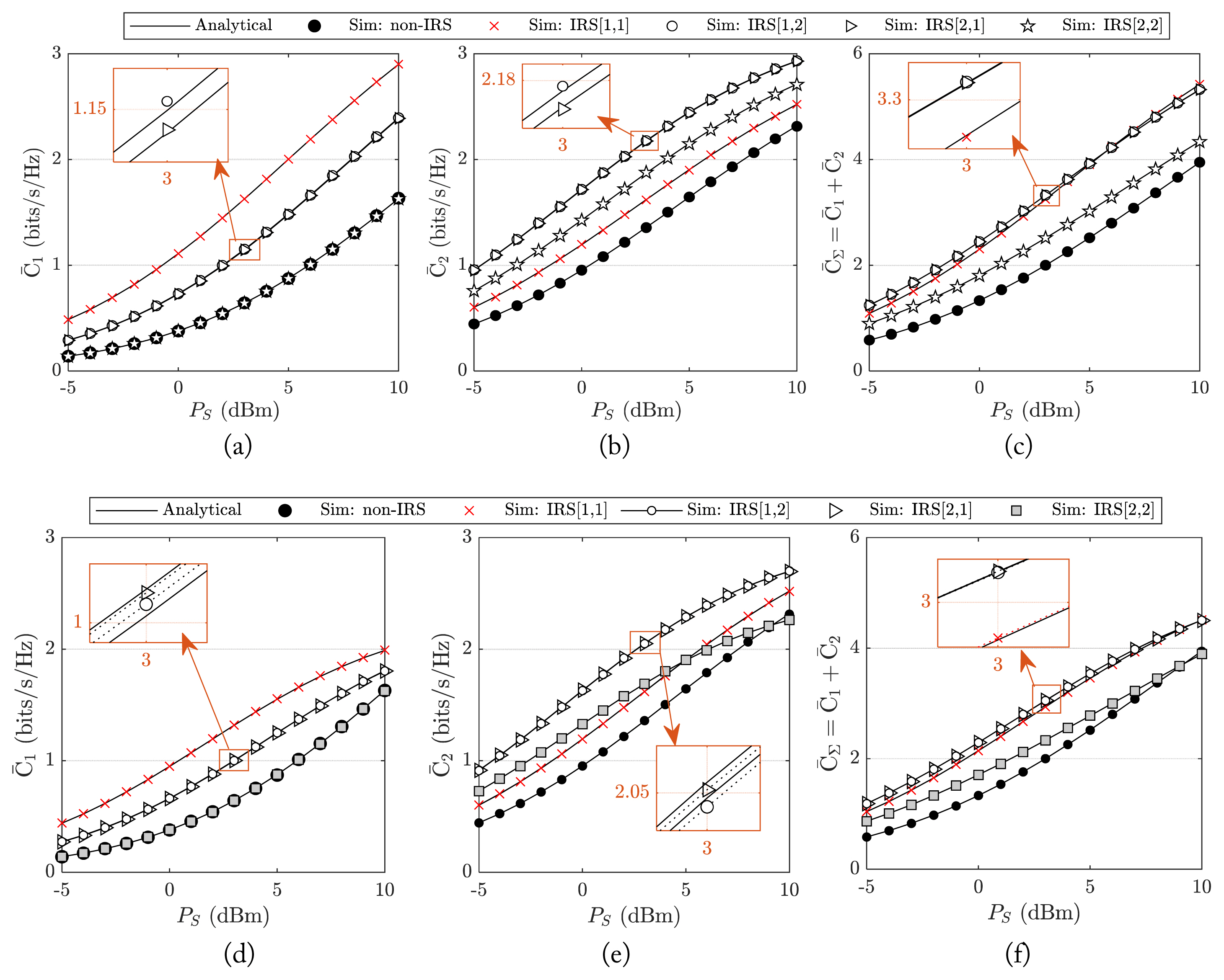
In Fig. 3, we show the advantage of using the IRS to assist NOMA communication via examining a simple IRS, including 2 RTs. We consider four possible cases denoted by IRS[m1, m2], m1, m2 ∈{1, 2}, which indicates that the first and the second RTs are allocated to Um1 and Um2, respectively. The AARs for x1, x2 and total AAR, C̄∑ = C̄1 + C̄2, for the ideal-IRS scenario (without the presence of the PD) are shown in Fig. 3(a)–3(c), respectively, and those of the non-ideal-IRS scenario (with the presence of the PD) are shown in Fig. 3(d)–3(f), respectively. The AARs are displayed as increasing functions of PS. Without the IRS, the received signal at each user propagates on the direct link and multi-path fading channel. Therefore, the AARs are very low, as shown as the lowest curves in Fig. 3. When the IRS is utilized, the AARs are significantly enhanced even with the presence of the PD. Although different levels of AAR enhancement are observed, these results still indicate the important role of the IRS in improving the RSSs at the users. As shown in Fig. 3(c) and 3(f), the total AARs for the cases of IRS[1,2] and IRS[2,1] (in these cases, the IRS assists the communication for both users) achieve better values than other cases.
In Fig. 4, we adopt the best IRS setup for the case of PS = 0 dBm with τPD = 0.1 (found in Fig. 3, i.e., IRS[2,1]) and then investigate the effect of the PA factors on the total AAR. The advantages of the NOMA scheme are confirmed by investigating a reference orthogonal multiple access (OMA) scheme. Due to the advantageous location of the near user, the system achieves a highest or lowest total-AAR when allocating all resources to the near user or the far user, respectively. When the SIC imperfection factor ζ increases, the total AAR becomes worse. For a performance comparison, we use a conventional OMA scheme, which defines the AAR for Um, m = {1, 2}, as
and the total AAR for OMA is given by
where υm ∈ (0, 1), υ1 + υ2 = 1, is the resource allocation (RA) factors for OMA (e.g., time allocation factor for TDMA or bandwidth allocation factor for FDMA). Compared to OMA, NOMA can achieve a higher total AAR in the presence of PD and imperfect-SIC. When ζ is sufficiently large, NOMA yields a lower performance compared to OMA. In Fig. 5, we show the joint effect of the RT-allocation strategy and PA factors, i.e., α1 and α2, on the AAR. Because the size of each RT is relatively small compared to the wave-propagation distances, the difference in distance between reflecting links is trivial. It is reasonable to assume that the signal attenuations of reflecting links toward a user are similar. For this reason, the RT allocation strategy is as follows. Let NU1 be the number of RTs allocated to U1. These NU1 RTs are assigned from left to right and from top to bottom. The other NU2 = N – NU1 RTs are assigned to U2. For a given value of NU1, C̄1 increases, while C̄2 decreases when we increase α1 and vice versa. This is because the power resource allocated for the users is defined by α1. For given PA factors, C̄1 is shown as an increasing function of NU1, whereas C̄2 improves with the first increase in NU1 and then reaches the optimal value. Finally, it degrades with further increases in NU1. The trend of C̄2 is explained as follows. Since both users need to decode x2 successfully, the IRS needs assist both users to gain the highest value of C̄2. Therefore, using very high or very low values of NU1 does not yield good values for C̄2. Although the highest total AAR is observed at (NU1 = 10, α1 = 1), the NOMA system does not use this configuration. The reason is that at this point, all system resources, including PS and RTs, are allocated to U1; hence, U2 is disconnected from the network. For our proposed NOMA system, we focus on the points lying on the intersection curve of the two user-AAR surfaces denoted by
ℓ ( N U 1 , α 1 * ) ℓ ( N U 1 , α 1 * ) ℓ * = max ℓ ( N U 1 , α 1 * ) ( N U 1 , α 1 * ) ( N U 1 , α 1 * )
In Fig. 6, we consider an IRS with a size of 2-by-Ncol RTs and then plot the optimal NOMA-AAR as shown in Fig. 6(a) and its respective optimal solution, i.e., optimal PA factors as shown in Fig. 6(b) and optimal RT-allocation as shown in Fig. 6(c) and 6(d), under different parameters of PS and ζ. Fig. 6(a) shows that the more RTs are used, the higher value for optimal NOMA-AAR is achieved. When the IRS’s size is sufficiently large, the increase in size does not gain much improvement in optimal NOMA-AAR. Therefore, the size of the IRS should be chosen carefully to achieve a reasonable trade-off between performance and cost. For instance, at ζ = 0.04 and PS = 0 dBm, the 2-by-1 and 2-by-4 IRSs can support 1 bit/s/Hz and 2 bit/s/Hz optimal NOMA-AAR, respectively. In Fig. 6(b)–6(d), we show the trends of the obtained optimal solutions. Regarding the NOMA principle, first, both users need to decode the signal allocated with stronger power, which is x2 for our proposed system, and consider the rest signals as interference, as shown in (12). After successfully decoding x2, U1 eliminates the signal x2 from its received signal and then decodes its desired signal x1, which is allocated with lower power. The allocated power for each signal is defined by the PA factors. Compared to x2, the decoding process of x1 deals with lower interference, which is caused by the imperfect-SIC decoder as shown in (13). For this reason, the AAR for x2, C̄2, significantly depends on the PA factors, and C̄2 increases when
α 1 * α 2 * α 1 * N U 1 * α 2 * α 1 * α 1 * N U 1 * N U 2 * N U 1 * N U 2 *
Hence, the smaller value for
α 1 * N U 1 *
In Fig. 7, we show the effects of the PD factor τPD and the reflection amplitude βRn on the system performance for two cases: with and without the presence of the LoS links. The results for the non-LoS case are obtained by set the source-to-user distances in (8) by very large values, i.e., dSUm → ∞. The optimal NOMA-AAR drops around 0.8 bits/s/Hz when the LoS links are not available. This indicates the importance of the LoS links; however, without the LoS links, the system can achieve a moderately optimal NOMA-AAR with the help of the reflecting link and the multi-path fading channel. When τPD increases, the total noise at each user increases. Hence, the optimal NOMA-AAR is displayed as a decreasing function of τPD as shown in Fig. 7(a). With the presence of a multi-path fading channel and/or LoS links, the influence of the PD on the optimal NOMA-AAR can be reduced; however, when the user is blocked and its communication only relies on the reflecting links, the value of τPD becomes a crucial factor to performance. Fig. 7(b) presents the optimal NOMA-AAR for different values of βRn. When βRn increases, the stronger received signal strengths are achieved at the users. Therefore, the optimal NOMA- AAR is shown as an increasing function of βRn. Moreover, the optimal NOMA-AAR for the case using the IRS is higher than that for the non-IRS case. This indicates the effectiveness of the IRS in improving system performance. Since βRn only affects the quality of the reflecting links, the influence of low βRn values can be reduced in the case of the presence of the LoS links or the stronger multi-path fading channel.
V. Conclusion
This paper considered an IRS-aided NOMA communication in the presence imperfect SIC. The theoretical results are derived and confirmed by Monte Carlo simulations. The numerical results showed that the NOMA communication achieves a significant enhancement in performance with the help of an IRS, and it outperforms the reference OMA system. The residual interference caused by the imperfect SIC leads to a remarkable degradation in performance. There is an optimal setup for the PA factors and the number of RTs allocated to each user that allows the best equal capacity for both users. The effects of key system parameters on the trends of the optimal setup were studied. For instance, more RTs are allocated to the near user when the number of available RTs increases. Moreover, a higher portion of transmit power is allocated to the far user when the source transmit power increases.