 |
 |
- Search
| J. Electromagn. Eng. Sci > Volume 21(3); 2021 > Article |
|
Abstract
This paper presents the design of a bidirectional same-sense circularly polarized (CP) antenna that uses metasurfaces. The antenna consists of two metasurfaces, each comprising an array of 2 × 4 corner truncated patches placed back-to-back on the top and bottom of the antenna. In addition, a ground plane with an etched slot is sandwiched between the substrates at the front and back, and the feed line is a 50 Ω coplanar waveguide. The antenna radiates same-sense right-handed CP waves in both the front and back directions and has overall dimensions of 48 mm × 24 mm × 3.048 mm (0.91λo × 0.45λo × 0.05λo at 5.7 GHz). The measured reflection coefficient for |S11| < −10 dB yields an impedance bandwidth of 5.21–6.26 GHz (18.4%) and an axial ratio (AR) bandwidth of 5.36–6 GHz (11.2%) for both front and back directions. The antenna gain is 3–5.29 dBic for both directions and has a radiation efficiency of >96% within its AR bandwidth.
Antennas with bidirectional radiation patterns are useful in mobile wireless communication systems such as microcellular base stations, high-speed wireless local area networks, microwave sensor networks, coal mines, street microcells, and indoor wireless access venues [1–3]. Further, circularly polarized (CP) antennas are commonly employed to enhance channel stability and reliability because they provide a stable connection between the transmitting and receiving terminals (regardless of antenna orientation). Conventionally, CP antennas are produced by exciting two orthogonal linearly polarized (LP) antennas with the same amplitude and 90° phase difference.
Recently, CP antennas with bidirectional radiation patterns have gained popularity because they provide large signal coverage and can mitigate multi-path distortion and polarization mismatches [4, 5]. Accordingly, several bidirectional antennas have been developed with LP and CP radiation patterns. Bidirectional antennas with CP radiation mostly produce different senses of polarization unless specifically designed for the same polarization sense in both hemispheres. This means that when a right-handed CP (RHCP) antenna radiates from one side, the sense of rotation at the opposite side will inevitably be left-handed CP (LHCP) [6–9].
Many studies have suggested the goal of attaining CP radiation of the same sense in opposite directions. For example, back-to-back, slot coupled patches were used to achieve same-sense CP radiation from the front and back in [10]. Further, a bidirectional microstrip antenna fed by a coplanar waveguide (CPW) to obtain CP radiation was proposed in [11]. The authors in [12] proposed a novel bidirectional waveguide antenna design with CP of the same sense in opposite radiating directions. Similarly, a single-layer single-feed antenna with bidirectional CP radiation of the same sense was presented in [13]. A composite, right-left-handed transmission line was used to feed two orthogonal wire dipole arrays spaced by λo/4 (where λo is the wavelength of the operating frequency in free space) to achieve bidirectional CP radiation of the same sense in [14]. The authors in [15] presented a bidirectional same-sense CP slot antenna using a polarization-converting surface, while the authors in [16] presented a bidirectional same-sense LHCP antenna using a 4 × 4 metasurface arranged in a back-to-back configuration. While they achieved wide impedance and axial ratio (AR) bandwidths, the gain was low (with different values in the top and bottom directions) and the antenna dimensions were quite large. In addition, the antenna had poor mechanical properties due to the microstrip feedline and an air gap between the radiator and the metasurface.
This paper presents the design of a bidirectional, same-sense CP antenna using metasurfaces, which has attracted extensive interest in antenna design over recent years [17–24]. The antenna consists of two identical 2 × 4 truncated patches (metasurfaces) placed back-to-back—one at the top and one at the bottom. Same-sense CP is obtained by truncating the metasurface patches at the top and bottom sides in opposite orientations. Through the use of 2 × 4 metasurfaces, a small compact size wideband bidirectional CP antenna is achieved without significant loss in performance. Moreover, the resulting bidirectional antenna demonstrates acceptable performance characteristics: an impedance bandwidth of 5.21–6.26 GHz (18.4%), an AR bandwidth of 5.36–6 GHz (11.2%), a peak gain of 5.29 dBic, and a radiation efficiency of >96% within the AR bandwidth. The antenna’s dimensions are 48 mm × 24 mm × 3.048 mm (0.91λo × 0.45λo × 0.05λo at 5.7 GHz).
The geometry and dimensions of the proposed bidirectional antenna are shown in Fig. 1. It can be observed in Fig. 1(a) that the antenna consists of two layers: the front metasurface printed on the top of Substrate 1 and the back metasurface printed on the bottom of Substrate 2. A ground plane with an etched slot is sandwiched between the two layers without an air gap. Substrates 1 and 2 are RO4003 (ɛr = 3.38, tanδ = 0.0027) with thicknesses of h1 = h2 = 1.524 mm. The metasurface is a periodic structure, with eight square metal plates arranged in a 2 × 4 layout with periodicity P. Further, a truncation (dimension LC) is made on the patches of size WP × WP, as shown in Fig. 1(b). The primary radiating element of the antenna is a slot of length LS and width WS etched on the ground plane [17–19], as shown in Fig. 1(c). This is sandwiched between the dielectric substrates, as shown in Fig. 1(d). The 50 Ω coplanar waveguide feed line is printed in the middle of the antenna structure, as shown in Fig. 1(d). The feedline characteristic impedance can be controlled by varying its width (Wf), while the stub (LO) is used to match the antenna impedance.
Each patch on the back-to-back metasurfaces is shaped as a truncated corner square patch [22–28] to produce CP radiation. To obtain same-sense CP, the truncated patches on the bottom of the metasurfaces are rotated by 90° with respect to the truncated patches at the tops of the metasurfaces (to ensure they can be in opposite orientations). If the orientation of the truncation at the top and bottom sides was the same, different senses of CP radiation would be observed in opposite directions. The optimized design parameters of the antenna for wide impedance, wide AR bandwidths, and bidirectional same sense CP radiation patterns are displayed in Table 1.
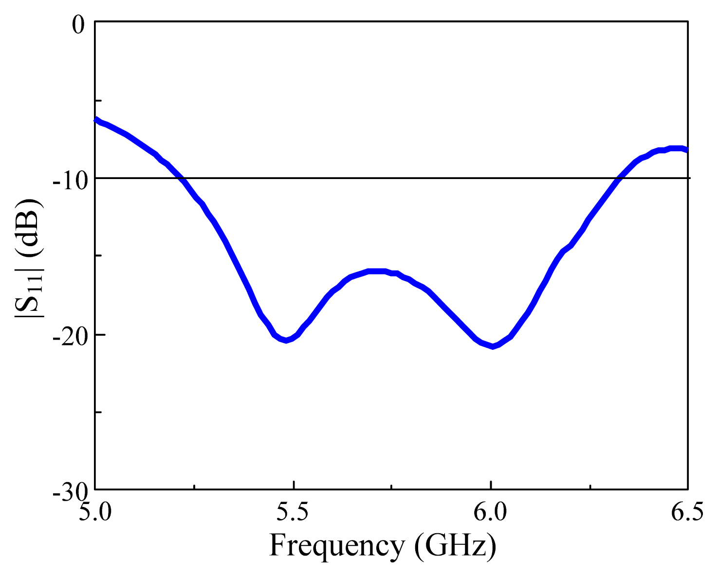
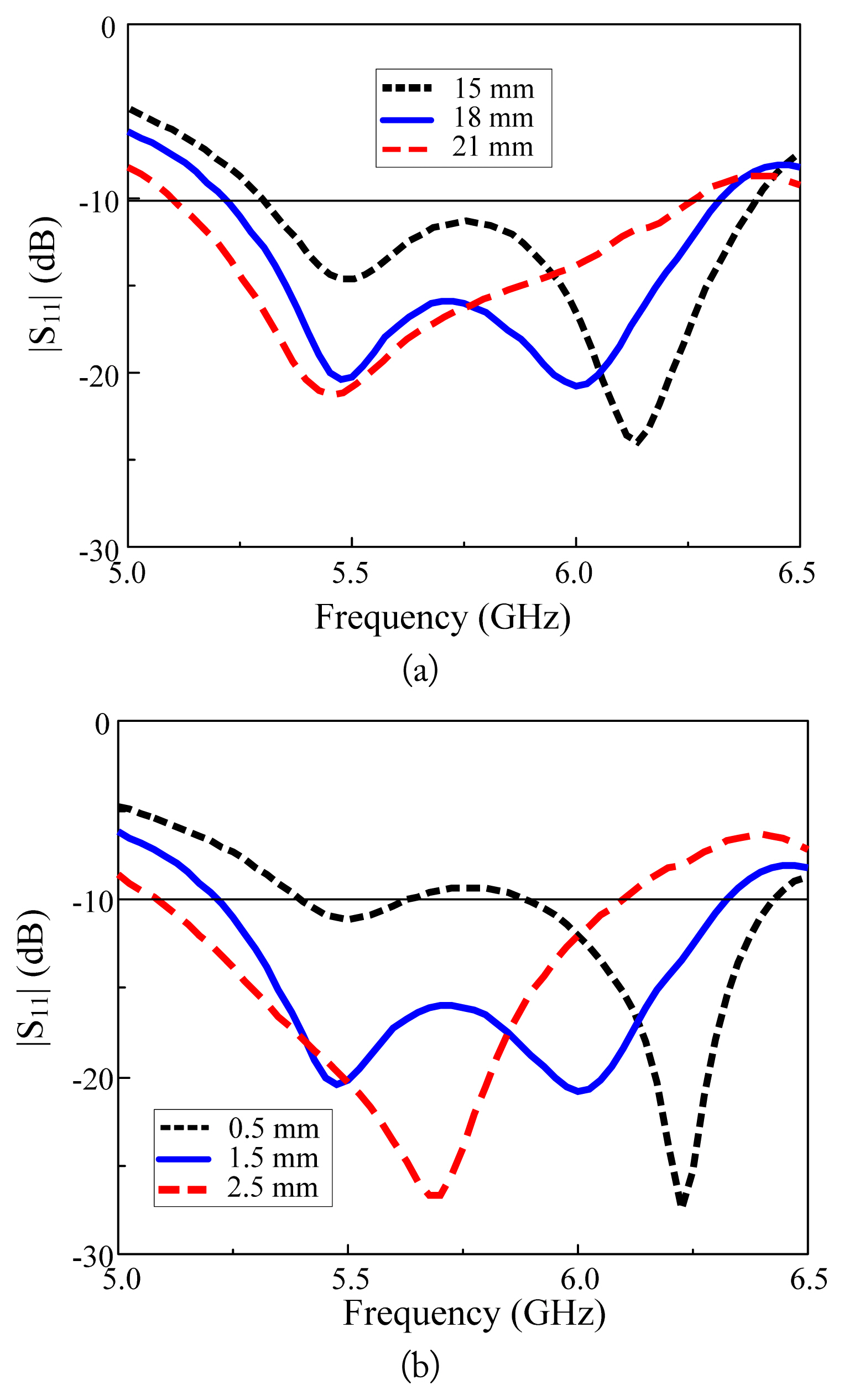
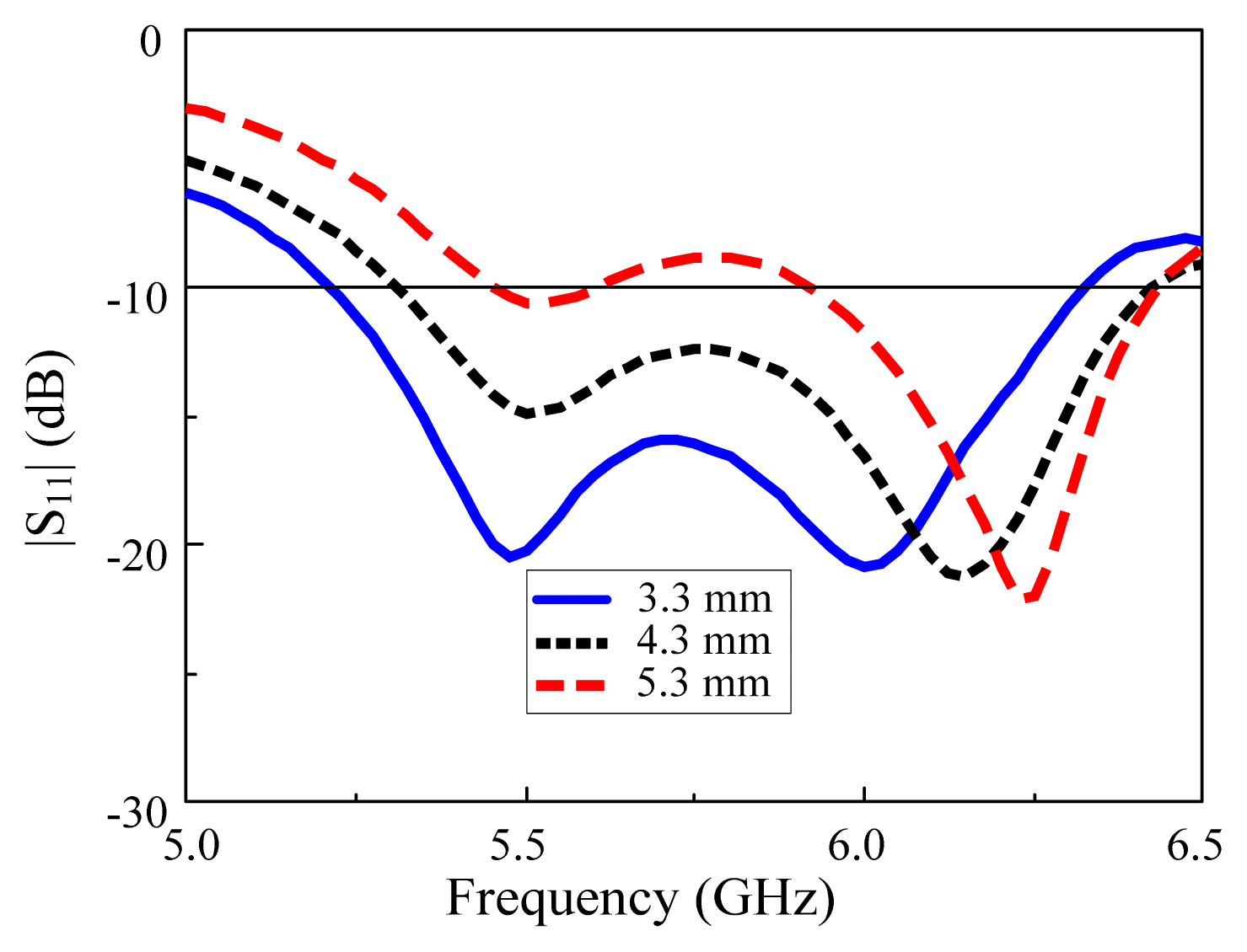
Simulation and optimization of the bidirectional CP antenna were performed with an Ansys High-Frequency Structure Simulator (HFSS), which is an electromagnetic wave simulator using a finite element method. In particular, the effects of key geometry on antenna characteristics were investigated. First, the response of the antenna was determined with all parameters fixed at their optimal values. Second, one design parameter was varied at a time during the parametric study. The simulated reflection coefficient of the antenna is shown in Fig. 2. The antenna exhibits an |S11| < −10 dB impedance bandwidth of 18.4% covering 5.21–6.26 GHz. Further, the effect of varying the slot length (LS) and slot width (WS) is shown in Fig. 3(a) and (b), respectively. It can be observed that when the slot length increased from 15 to 18 mm, the resonance shifted to the lower frequencies. Similarly, when the slot width increased from 1.5 to 2.5 mm, the resonance also shifted to the lower frequencies. The stub length (LO) was varied to achieve impedance matching, as shown in Fig. 4. When the stub length LO = 5.3 mm, the impedance of the antenna was not fully matched. However, when LO decreased to 4.3 and 3.3 mm, the resonance frequency reduced and good impedance matching was obtained. At LO = 3.3 mm, the antenna was fully matched.
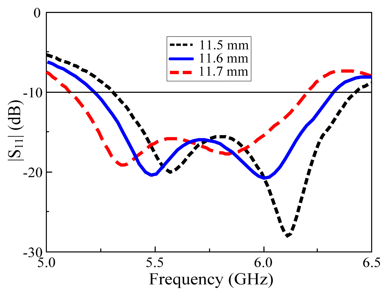
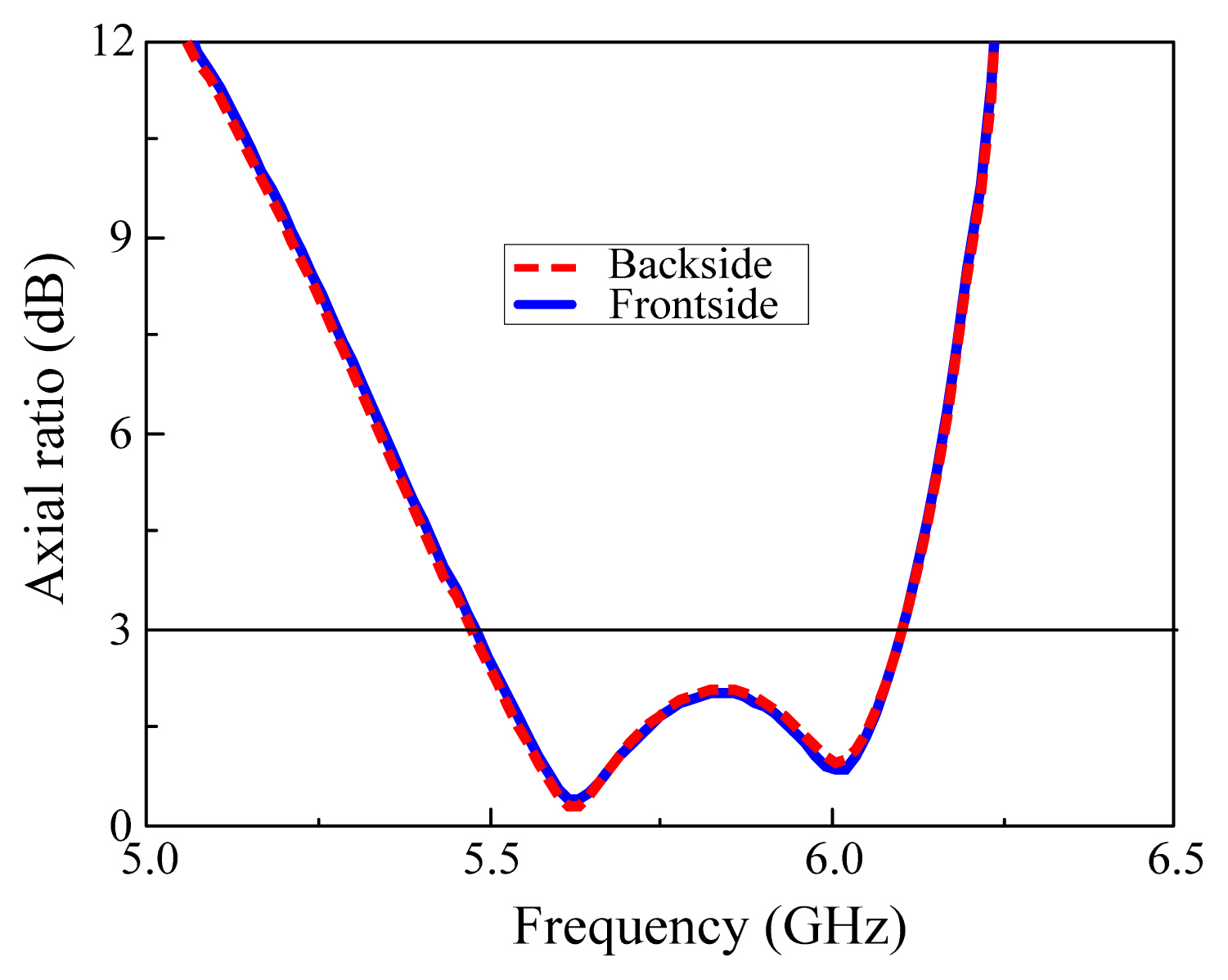
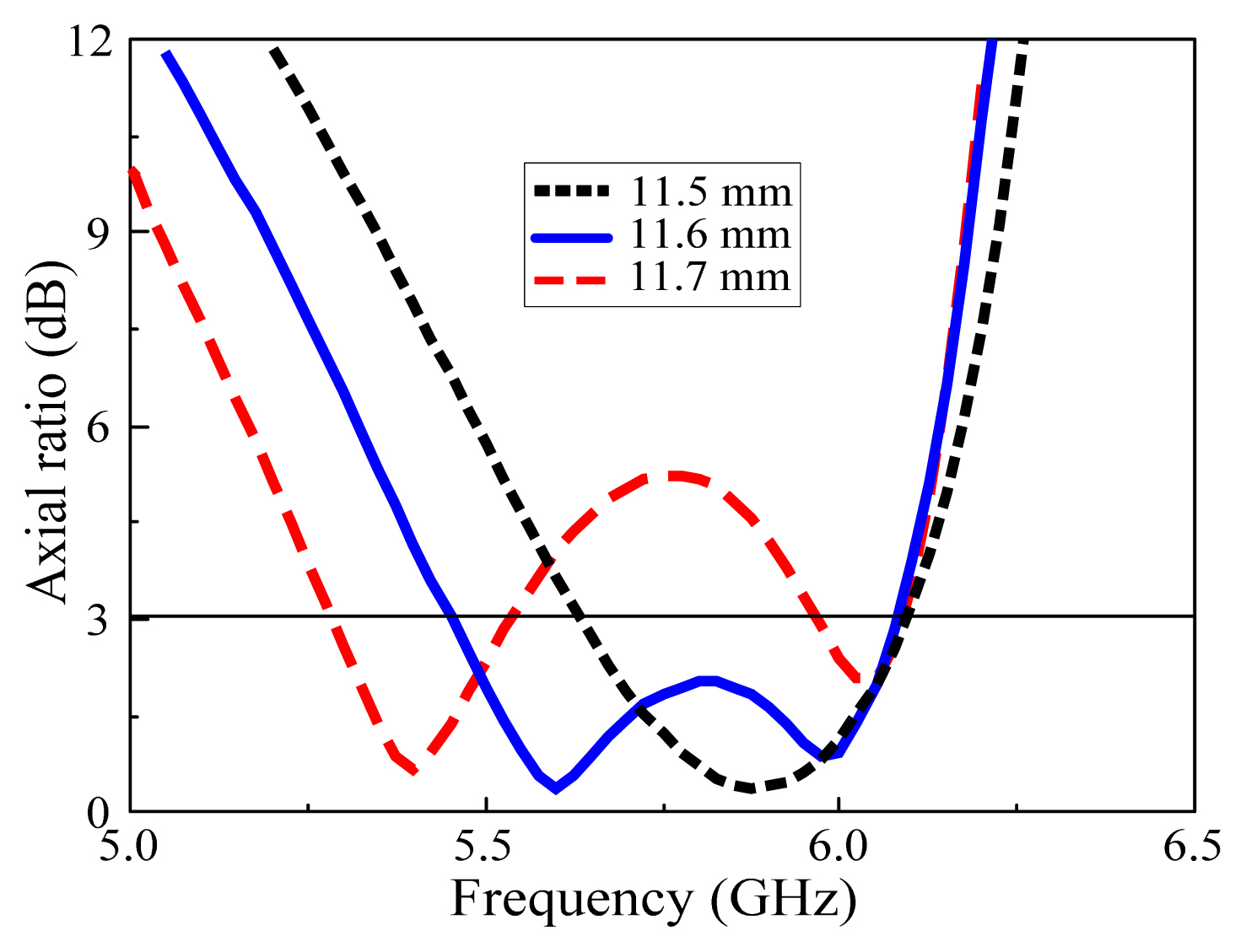
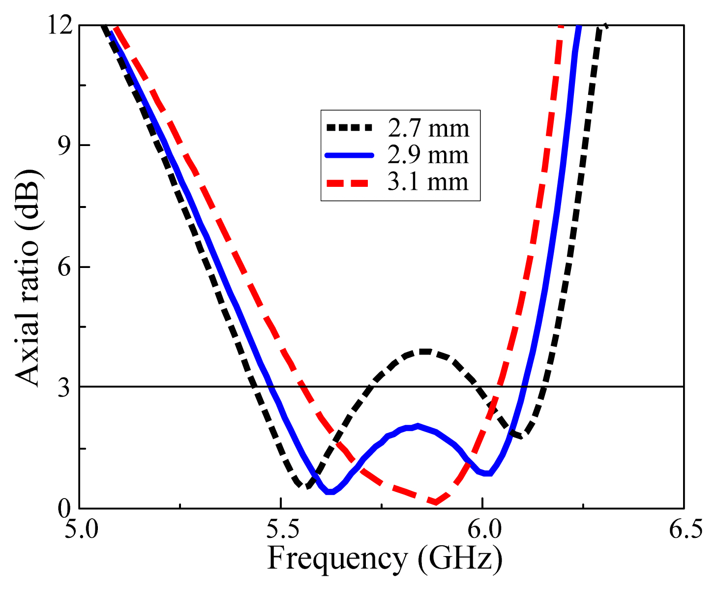
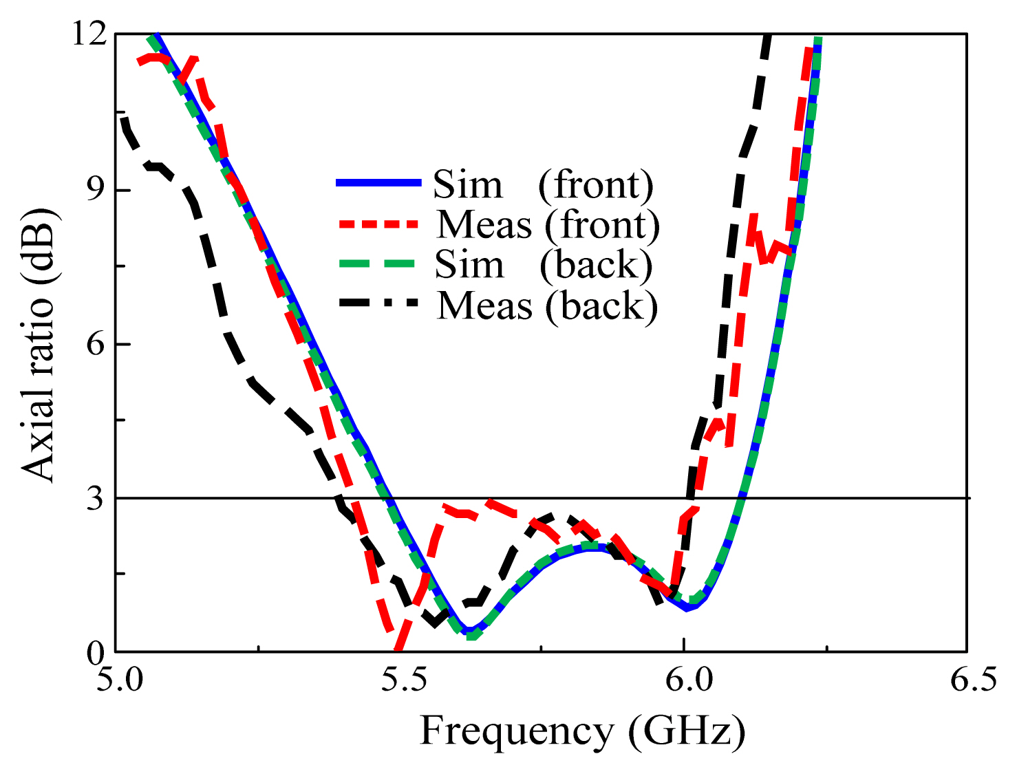
As shown in Fig. 5, an increase in the patch size of the antenna also shifted the resonance frequency downwards. Further, Fig. 6 indicates that the antenna produced almost the same AR characteristics for both its front (θ = 0°) and back (θ = 180°). Its AR bandwidth ranged from 5.36–6.0 GHz, equating to a fractional bandwidth of 11.2%. The effects of varying the metasurface patch and corner cut sizes on the AR are shown in Figs. 7 and 8, respectively. Further, an increase in the metasurface patch size WP from 11.6 to 11.7 mm shifted the AR bandwidth to lower frequencies, while a decrease in patch size from 11.6 to 11.5 mm shifted the AR bandwidth to higher frequencies (Fig. 7). When the corner cut size LC was increased from 2.7 to 2.9 mm, there was a considerable improvement in AR performance. Moreover, a further increase in the cut size from 2.9 to 3.1 mm narrowed the AR bandwidth, as shown in Fig. 8.
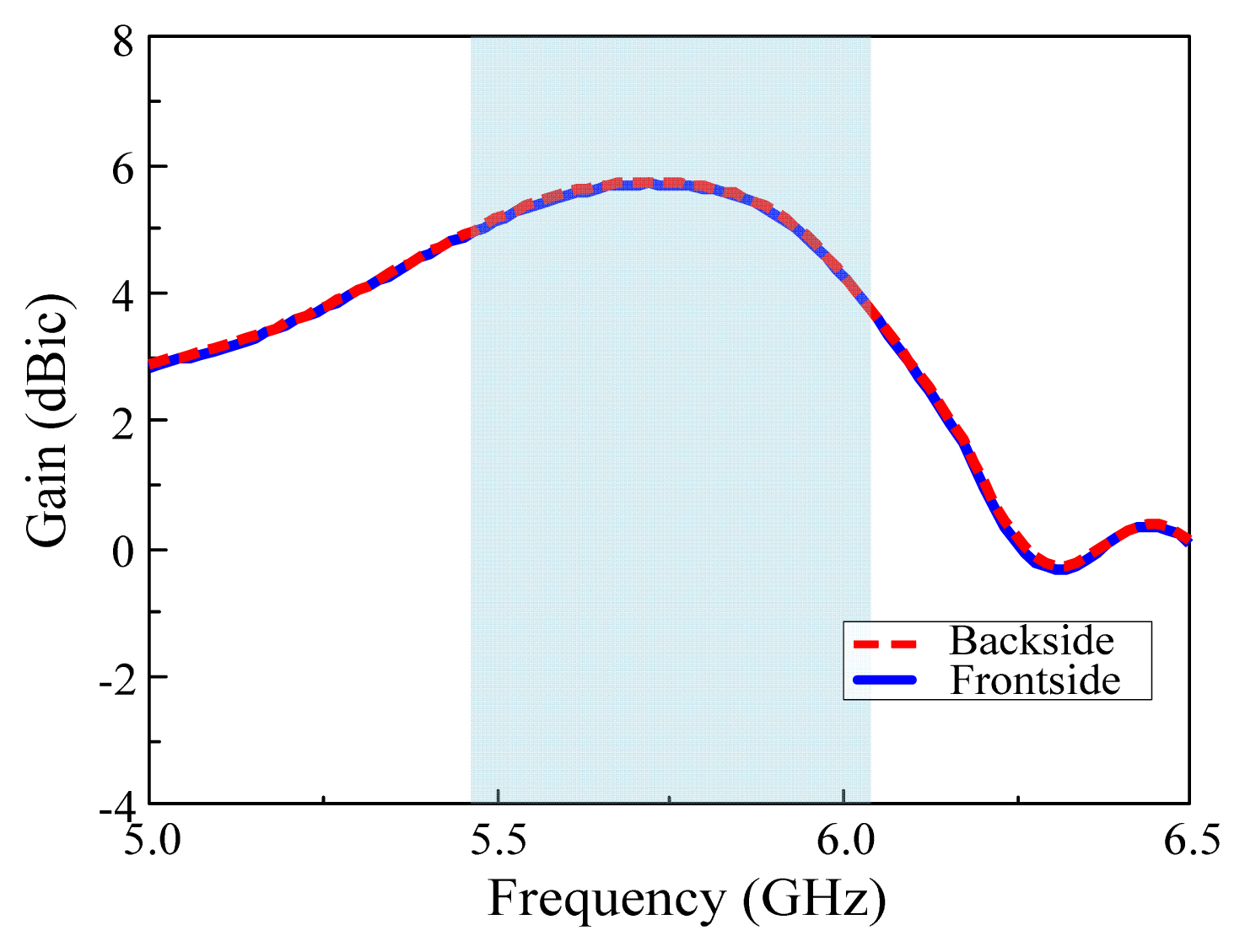
The gain of the antenna is presented in Fig. 9, where it can be observed that the gain was almost identical for both the front and back. The antenna also exhibited stable gain characteristics, with an average gain of 4.6 dBic within the AR bandwidth. The simulated radiation patterns in the x–z and y–z planes for both RHCP (co-polarization) and LHCP (cross-polarization) at 5.7 GHz are presented in Fig. 10(a) and (b), respectively. Here, good symmetrical RHCP bidirectional radiation and low cross-polarization can be observed. Further, by truncating the metasurface patches at the top and bottom sides of the antenna in opposite orientations, RHCP was achieved.
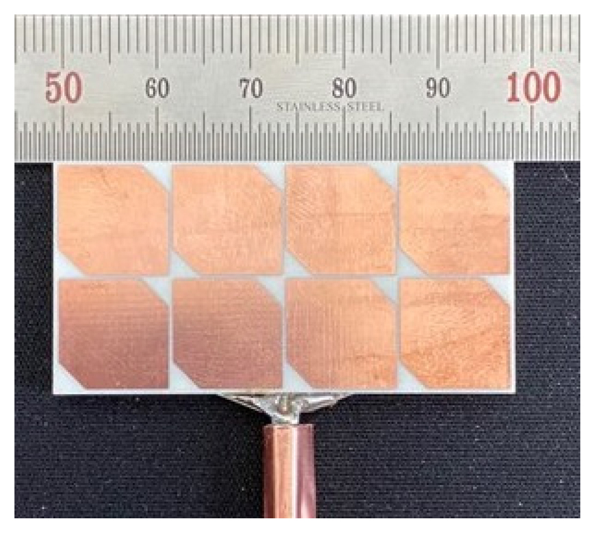
The proposed bidirectional CP antenna was fabricated and measured to verify our design concept, and a photograph of which is presented in Fig. 11. For S-parameter measurement, an Agilent N5230A network analyzer and a 3.5 mm coaxial calibration standard GCS35M were employed. Far-field measurements were conducted at the RFID/USN Center, Incheon, Republic of Korea. For the radiation pattern measurements, a full anechoic chamber and an Agilent E8362B network analyzer were employed. The proposed bidirectional antenna was used for reception, and a standard wideband horn antenna was used for transmission, with a transmission distance of 10 m established between them.
The proposed antenna was rotated from −180° to + 180° at 3°/s and a 1° scan angle while maintaining the position of the horn antenna. Overall, the proposed antenna achieved good agreement between the simulated and measured data. However, there were minimal disparities between the measurements and the HFSS simulations, which could be due to slight alignment errors during fabrication. The measured and simulated reflection coefficients for the fabricated antenna are displayed in Fig. 12. The measured impedance bandwidth for |S11| < −10 dB was 5.21–6.26 GHz (18.4%), which is quite similar to the simulated impedance bandwidth of 5.21–6.25 GHz (18.2%). Further, Fig. 13 shows the measured and simulated gains for the front and back of the bidirectional antenna with a simulated average gain of 4.6 dBic and a measured average gain of 4.27 dBic. The AR and radiation patterns of the prototype at 5.7 GHz were measured and are displayed in Figs. 10 and 14, respectively. In addition, Fig. 14 shows the measured and simulated AR bandwidth for both the front and back. The simulated AR bandwidth was 5.44–6.10 GHz (11.5%) and the measured AR bandwidth was 5.36–6 GHz (11.2%) The measured and simulated radiation patterns of the antenna in the x–z and y–z planes for both RHCP and LHCP are depicted in Fig. 10(a) and (b), respectively. The measured and simulated radiation patterns demonstrate good symmetrical RHCP bidirectional radiation and low cross-polarization.
Further, a comparison of the performance of the proposed antenna to that of other bidirectional antenna designs described in the literature is presented in Table 2. The proposed antenna exhibited wide impedance bandwidth, wide 3 dB AR bandwidth, good symmetric bidirectional radiation, and high gain. Although the structure reported in [12] achieved a wider impedance bandwidth compared to our design, its low gain represents a significant drawback. Moreover, the designs reported in [10, 11], and [13–15] achieved lower gains and significantly smaller operating bandwidths compared to the proposed antenna.
A bidirectional antenna with same-sense CP was proposed in this paper. The bidirectional antenna consists of two 2 × 4 truncated metasurface patches, one at the top and one at the bottom of the antenna. It radiates same-sense RHCP waves in both the front and back directions. Further, the antenna produces good symmetric bidirectional RHCP radiation patterns, an impedance bandwidth of 5.21–6.26 GHz (18.4%), an AR bandwidth of 5.36–6 GHz (11.2%), a bidirectional gain of 3–5.29 dBic (within the AR bandwidth), and a high radiation efficiency of >96%. These characteristics render the proposed antenna suitable for wireless communication in environments such as tunnels, long streets, and coal mines.
Acknowledgments
This work was supported in part by the National Research Foundation (NRF) of Korea grant funded by the Korean government (MSIT) (No. 2018R1D1A1A-02086071); in part by the GRRC program of Gyeonggi province (GRRC AJOU 2016B01, Photonics-Medical Convergence Technology Research Center).
Fig. 1
(a) A 3D-view of antenna, (b) truncated 2 × 4 front/side metasurface patches, (c) slot etched on ground plane, and (d) side view.
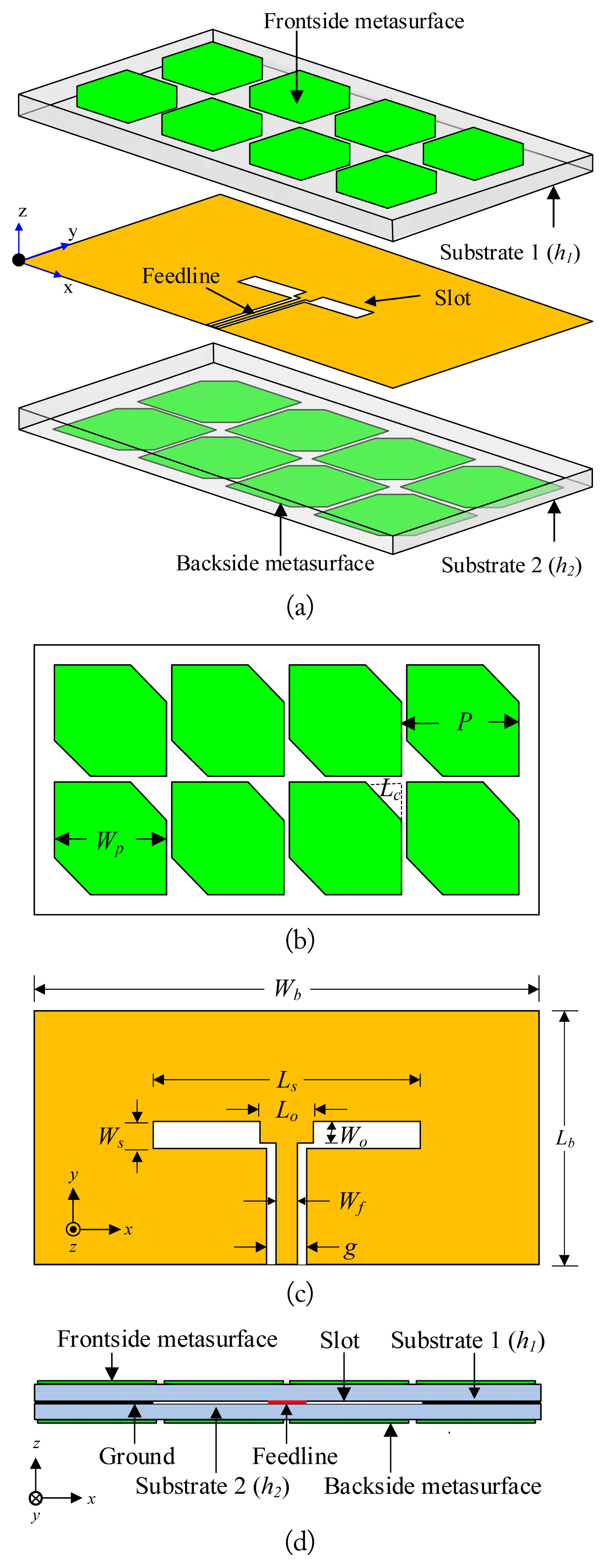
Fig. 10
Measured and simulated radiation pattern of the antenna at 5.7 GHz: (a) x–z plane and (b) y–z plane.
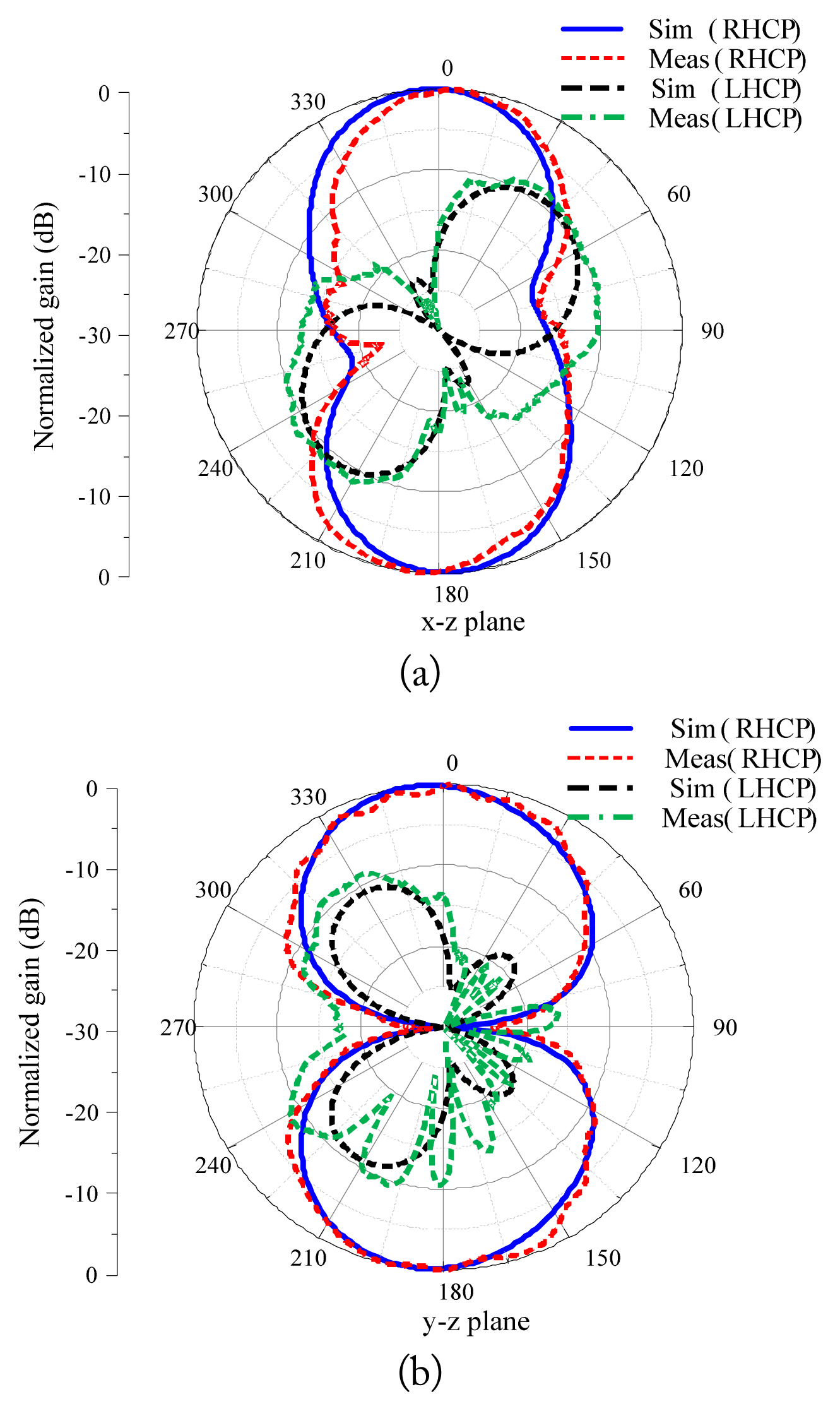
Table 1
Optimized design parameters
| Parameter | Dimension (mm) |
|---|---|
| P | 12 |
| WP | 11.6 |
| LS | 18 |
| WS | 1.5 |
| LC | 2.9 |
| LO | 3.3 |
| g | 0.4 |
| WO | 2.4 |
| Wh | 48 |
| Lb | 24 |
| Wf | 0.5 |
| h1 = h2 | 1.524 |
Table 2
Performance comparison of the proposed antenna with other antenna designs
| Antenna structure | Size (λo) | −10 dB BW (%) | AR BW (%) | Peak gain (dBic) | Center freq. (GHz) |
|---|---|---|---|---|---|
| Hou et al. [10] | 0.73 × 0.73 × 0.04 | 3.8 | 1.3 | 3.09 | 2.46 |
| Zhang et al. [11] | 1.32 × 0.88 × 0.07 | 11.6 | 2.55 | – | 4.42 |
| Zhao et al. [12] | 0.62 × 0.62 × 1.17 | 29.5 | 7.8 | 3.8 | 2.44 |
| Ye et al. [13] | 0.53 × 0.47 × 0.029 | 2.5 | 2.8 | 4.04 | 5.8 |
| Liu et al. [14] | 1.00 × 0.50 × 0.50 | 12 | 11.8 | 4.2 | 2.54 |
| Khosravi and Mousavi [15] | 0.75 × 0.75 × 0.15 | 5 | 2 | 1.8 | 1.56 |
| Hussain et al. [16] | 0.86 × 0.67 × 0.13 | 21.5 | 14.3 | 4.8 | 5.60 |
| Proposed | 0.91 × 0.45 × 0.05 | 18.4 | 11.2 | 5.29 | 5.70 |
References
1. MM Alam, "Microstrip antenna array with four port Butler matrix for switched beam base station application," In: Proceedings of 2009 12th International Conference on Computers and Information Technology; Dhaka, Bangladesh. 2019, pp 531–536.

2. T Hori, K Cho, and K Kagoshima, Bidirectional base station antenna illuminating a street microcell for personal communication system. In: Proceedings of 1995 9th International Conference on Antennas and Propagation (ICAP); Eindhoven, Netherlands. 1995, p.419–422.
3. JCS Chieh and AV Pham, "A bidirectional microstrip X-band antenna array on liquid crystal polymer for beam-forming applications," IEEE Transactions on Antennas and Propagation, vol. 61, no. 6, pp. 3364–3368, 2013.

4. YF Lin, HM Chen, FH Chu, and SC Pan, "Bidirectional radiated circularly polarized square-ring antenna for portable RFID reader," Electronics Letters, vol. 44, no. 24, pp. 1383–1384, 2008.

5. Y Zhao, KP Wei, ZJ Zhang, and ZH Feng, "A bidirectional waveguide antenna with polarization reconfigurable capability," Microwave and Optical Technology Letters, vol. 56, no. 2, pp. 422–427, 2014.

6. J Shen, C Lu, W Cao, J Yang, and M Li, "A novel bidirectional antenna with broadband circularly polarized radiation in X-band," IEEE Antennas and Wireless Propagation Letters, vol. 13, pp. 7–10, 2013.

7. J Hu, Q Wu, and X Wang, "A wideband millimeter-wave bidirectional circularly polarized antenna array using sequential rotation feeding," In: Proceedings of 2018 IEEE International Symposium on Antennas and Propagation & USNC/ URSI National Radio Science Meeting; Boston, MA. 2018, pp 611–612.

8. E Aloni and R Kastner, "Analysis of a dual circularly polarized microstrip antenna fed by crossed slots," IEEE Transactions on Antennas and Propagation, vol. 42, no. 8, pp. 1053–1058, 1994.

9. D Wu, Y Fan, M Zhao, and Z He, "A new kind of millimeter wave dual-circular polarized array," In: Proceedings of 2008 8th International Symposium on Antennas, Propagation and EM Theory; Kunming, China. 2008, pp 338–340.

10. Y Hou, Y Li, L Chang, Z Zhang, and Z Feng, "Bidirectional same-sense circularly polarized antenna using slot-coupled back-to-back patches," Microwave and Optical Technology Letters, vol. 59, no. 3, pp. 645–648, 2017.

11. QY Zhang, GM Wang, and DY Xia, "Bidirectional circularly polarized microstrip antenna fed by coplanar waveguide," In: Proceedings of 2006 7th International Symposium on Antennas, Propagation & EM Theory; Guilin, China. 2016, pp 1–3.

12. Y Zhao, K Wei, Z Zhang, and Z Feng, "A waveguide antenna with bidirectional circular polarizations of the same sense," IEEE Antennas and Wireless Propagation Letters, vol. 12, pp. 559–562, 2013.

13. M Ye, XR Li, and QX Chu, "Single-layer single-fed endfire antenna with bidirectional circularly polarized radiation of the same sense," IEEE Antennas and Wireless Propagation Letters, vol. 16, pp. 621–624, 2016.

14. W Liu, Z Zhang, and Z Feng, "A bidirectional circularly polarized array of the same sense based on CRLH transmission line," Progress In Electromagnetics Research, vol. 141, pp. 537–552, 2013.

15. F Khosravi and P Mousavi, "Bidirectional same-sense circularly polarized slot antenna using polarization converting surface," IEEE Antennas and Wireless Propagation Letters, vol. 13, pp. 1652–1655, 2014.

16. N Hussain, SI Naqvi, WA Awan, and TT Le, "A metasurface-based wideband bidirectional same-sense circularly polarized antenna," International Journal of RF and Microwave Computer-Aided Engineering, vol. 30, no. 8, article no. e22262, 2020.
https://doi.org/10.1002/mmce.22262

17. I Park, "Application of metasurfaces in the design of performance-enhanced low-profile antennas," EPJ Applied Metamaterials, vol. 5, article no 11, 2018.
https://doi.org/10.1051/epjam/2018008

18. SX Ta and I Park, "Low-profile broadband circularly polarized patch antenna using metasurface," IEEE Transactions on Antennas and Propagation, vol. 63, no. 12, pp. 5929–5934, 2015.

19. SX Ta and I Park, "Compact wideband circularly polarized patch antenna array using metasurface," IEEE Antennas and Wireless Propagation Letters, vol. 16, pp. 1932–1936, 2017.

20. W Liu, ZN Chen, and X Qing, "Metamaterial-based low-profile broadband mushroom antenna," IEEE Transactions on Antennas and Propagation, vol. 62, no. 3, pp. 1165–1172, 2014.

21. W Liu, ZN Chen, and X Qing, "Metamaterial-based low-profile broadband aperture-coupled grid-slotted patch antenna," IEEE Transactions on Antennas and Propagation, vol. 63, no. 7, pp. 3325–3329, 2015.

22. SX Ta and I Park, "Planar wideband circularly polarized metasurface-based antenna array," Journal of Electromagnetic Waves and Applications, vol. 30, no. 12, pp. 1620–1630, 2016.

23. HL Zhu, SW Cheung, XH Liu, and TI Yuk, "Design of polarization reconfigurable antenna using metasurface," IEEE Transactions on Antennas and Propagation, vol. 62, no. 6, pp. 2891–2898, 2014.

24. Y Huang, L Yang, J Li, Y Wang, and G Wen, "Polarization conversion of metasurface for the application of wide band low-profile circular polarization slot antenna," Applied Physics Letters, vol. 109, no. 5, article no 054101, 2016.
https://doi.org/10.1063/1.4960198

25. J Ju, D Kim, W Lee, and J Choi, "Design method of a circularly-polarized antenna using Fabry-Perot cavity structure," ETRI Journal, vol. 33, no. 2, pp. 163–168, 2011.

26. J Ju and D Kim, "Circularly-polarised high gain cavity antenna based on sequentially rotated phase feeding," Electronics Letters, vol. 49, no. 19, pp. 1198–1200, 2013.

27. A Chen, Y Zhang, Z Chen, and S Cao, "A Ka-band high-gain circularly polarized microstrip antenna array," IEEE Antennas and Wireless Propagation Letters, vol. 9, pp. 1115–1118, 2010.
Biography

Cho Hilary Scott Nkimbeng received his B.Tech. degree in electrical and electronic engineering (telecommunication) from the University of Buea, Cameroon, in 2013 and an M.S. degree in Electrical and Computer Engineering from Ajou University, Suwon, Republic of Korea, in 2018. He is currently studying for his Ph.D. at the Department of Electrical and Computer Engineering at Ajou University, Suwon, Korea. His research interests include metasurface antennas, metamaterial-based antennas, circularly polarized antennas, miniaturized antennas, and bidirectional antennas.
Biography

Heesu Wang received his B.S. and M.S. degrees in Electrical and Computer Engineering from Ajou University, Suwon, Korea, in 2018 and 2020, respectively. He is currently studying for his Ph.D. at the Department of Electrical and Computer Engineering at Ajou University, Suwon, Korea. His research interests include the design of patch antennas, printed antennas, small antennas, and metasurface antennas for various wireless communication applications.
Biography

Ikmo Park received his B.S. degree in Electrical Engineering from the State University of New York at Stony Brook and his M.S. and Ph.D. degrees in Electrical Engineering from the University of Illinois at Urbana-Champaign. He joined the Department of Electrical and Computer Engineering at Ajou University, Suwon, Korea, in 1996, where he is currently a Professor. He has authored and co-authored over 300 technical journals and conference papers. He also holds over 40 domestic and international patents. He served as a Chair of the Department of Electrical and Computer Engineering at Ajou University, and he is a member of the Board of Directors at the Korea Institute of Electromagnetic Engineering and Science (KIEES). He also serves as the Editor-in-Chief for the Journal of KIEES, an Editorial Board member for the International Journal of Antennas and Propagation, an Editorial Board member for MDPI’s Electronics, and an Associate Editor for the IET’s Electronics Letters. He has also served as an Editorial Board member of the Journal of Electromagnetic Engineering and Science. He currently serves as chair, organizer, and member of program committees for various conferences, work-shops, and short courses in electromagnetic-related topics. His present research interests include the design and analysis of microwave, millimeter-wave, terahertz wave, and nano-structured antennas with metamaterials and metasurfaces.
- TOOLS


