Design and Characterization of Wideband Printed Antenna Based on DGS for 28 GHz 5G Applications
Article information
Abstract
In this paper, a compact, wideband, printed antenna is proposed for millimeter-wave fifth-generation communication systems. The proposed design is a patch antenna with a defected ground structure, in which ground plane defects are utilized to reduce resonance and achieve wideband operation. The optimized antenna dimensions are 2.5 mm × 4.5 mm with a substrate thickness of 0.203 mm. A prototype antenna was fabricated and measured to verify the performance, and it was established that the simulated and measured results were in good agreement. The measured bandwidth was approximately 6.4 GHz (26.5–32.9 GHz) with a peak gain of 5.62 dBi and an efficiency in operational bandwidth of 84%. The compactness, wide bandwidth, and decent gain suggest that the proposed antenna is a potential contender for forthcoming communication systems.
I. Introduction
The evolution of fifth-generation (5G) communication systems will lead us into an era of ubiquitous connectivity and the Internet of Things (IoT) [1]. The main purpose of the IoT is to strengthen new user experiences and to link new industries with enhanced performance, security, and affordable prices [2]. Importantly, the aim of 5G is to attain a peak data rate of 20 Gbps by utilizing the millimeter-wave (mm-wave) spectrum [3]. However, for the effective implementation of 5G systems, efficient and compact antennas operating at the mm-wave frequency band will be required. Moreover, mm-wave 5G antennas with a large operating bandwidth and high gain will be necessary [4]. At the ITU World Radiocommunication Conference 2019 (WRC19), global stakeholders approved bands for 5G communication. One of these was the 28 GHz band, which has the greatest potential for 5G mm-wave communication [5]. Consequently, the attention of researchers has been drawn towards this band for future communication applications [6–14].
Recent literature has reported various antenna designs for 5G mm-wave applications [6–14]. For example, the work in [6, 7] employed metasurfaces and single patch antennas for gain and bandwidth enhancement, which increased both the overall size and design complexity of the structure. In addition, the air gap between the frequency selective surface (FSS) and the antenna introduced a complexity, because a small change in the gap had a greater impact on the performance of the antenna due to the shorter wavelength at mm-wave frequencies. The work reported in [8] used an additional waveguide with a patch antenna to achieve a tilted beam radiation pattern. However, this resulted in the antenna being physically large with a limited bandwidth. In [9], a bow-tie antenna was presented to achieve wide bandwidth and high gain. However, due to the large dimensions, its suitability for compact devices would be limited.
Array antennas have also been proposed for 28 GHz mm-wave applications [10–12]. Here, wide operational bandwidth with the advantages of high gain and compact size were reported. However, these antennas suffered from being complex structures with low radiation efficiency. In [13], a slot etching technique was employed in the design of a compact-sized dual-band antenna for 28 and 38 GHz applications, although the reported bandwidth and gain were unsuitable for 5G applications. Finally, a monopole antenna for mm-wave applications was proposed in [14]. Although the antenna exhibited omni-directional radiation patterns, it achieved low gain and limited bandwidth.
To overcome the limitations of these previous designs, a compact antenna operating at the mm-wave 5G frequency spectrum is proposed in this paper. The proposed geometry attains a wide bandwidth and significant gain. The miniaturization of the antenna and performance enhancement is achieved by incorporating the defects in the ground layer. The remainder of the paper is organized as follows: Section II presents the antenna design methodology, Section III provides an explanation of the various performance parameters, and the discussion and conclusions are presented in Section IV. The salient features of the proposed antenna can be summarized as follows: (1) a simple rectangular slot was used to shift frequency to lower bands without increasing antenna size, (2) it exhibits wide operational bandwidth with simple geometrical configuration, whereas complex defected ground structures (DGSs) were used for a similar purpose in the reported literature, and (3) the combination of compact size, wide bandwidth, high gain, and high efficiency renders the antenna a potential candidate for 28 GHz 5G communication systems.
II. Antenna Design and Performance Analysis
The finite element-based electromagnetic solver software, Higher Frequency Structural Simulator (HFSS), was used to model and analyze the antenna design. Designing the antenna was divided into two steps, and a detailed description of the design process is provided in the subsequent sections.
1. Step 1
Initially, a conventional rectangular patch antenna was modeled on a Rogers RO4003 substrate with a relative permittivity (ɛr) of 3.55, a loss tangent of 0.002, and a thickness of 0.203 mm. The bottom of the substrate was a full ground plane, as depicted in Fig. 1(a).
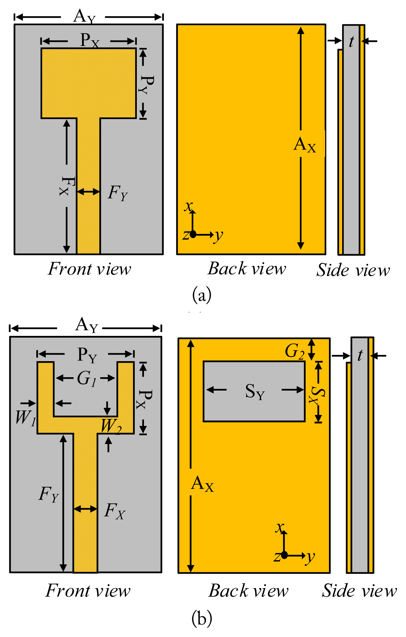
Design evolution of the proposed antenna: (a) conventional patch and (b) the proposed patch antenna.
The antenna dimensions were 2.5 mm × 4.5 mm and it was designed to operate in the fundamental TM01 mode. The resonating frequency (fr) is defined as follows [15]:
where λg is the guided wavelength at the desired frequency and ɛeff is the effective dielectric constant, which is given by
Here, Wp is the width of the radiator and h is the thickness of the substrate. The length (LP) of the radiator can be estimated by using
Theoretically, this antenna resonates at half-wavelength with a full ground plane. Further, the reflection coefficient plot in Fig. 2 demonstrates that the antenna is resonating at 50 GHz. The optimized parameters for a conventional patch are as follows: AX = 5 mm, AY = 5 mm, t = 0.20 mm, PY = 4.5 mm, PX = 2.5 mm, FX = 2 mm, and FY = 0.8 mm.

S-parameters of the antenna for different geometrical configurations.
2. Step 2
In the second step, a rectangular slot was etched in the ground plane as a defect, as illustrated in Fig. 1(b). After this alteration, the antenna behaved like a monopole antenna and started resonating at a quarter wavelength. This explains why the frequency shifted to almost half of the initially designed antenna, as depicted in Fig. 2. Thus, the antenna behaved like a monopole antenna after introducing the DGS, the length of which can be estimated by using the following equation (given in [16]):
The dimensions of the radiating slot can be calculated in terms of an integral multiple of the wavelength at the desired frequency. For the presented case, the length and width of the slot can be determined from the following relation:
Here, fr is the central frequency and x1 and x2 are found to be 4 and 8. To enhance the matching performance at the desired frequency of 28 GHz and to attain a wider bandwidth, the primary radiator was modified by subtracting a rectangular slit from the upper side of the patch antenna, as shown in Fig. 1(b). The reflection coefficient plot in Fig. 2 demonstrates that the antenna with a rectangular slit and the DGS resonated at a lower frequency (approximately 27.5 GHz) with a wide operating band, while retaining the other antenna dimensions. It can also be observed that without the DGS, the antenna achieved an impedance bandwidth of 3.4 GHz (48.3–51.7 GHz). By comparison, a very large impedance bandwidth of 6.3 GHz (26.4–32.7 GHz) was obtained with the DGS.
Initially, the length and width of the substrate were the same, as in Case 1. However, due to the bigger size of the end launch connector, the dimensions of the proposed antenna were optimized to obtain the desired results. The optimized parameters for the proposed antenna design were as follows: AX = 15 mm, AY = 15 mm, t = 0.203 mm, PY = 4.5 mm, PX = 2.5 mm, FX = 10 mm, FY = 0.8 mm, W1 = 0.4 mm, W2 = 0.4 mm, G1 = 3.7 mm, G2 = 2.5 mm, GY = 5.2 mm, and GX = 1.9 mm.
3. Performance Analysis of the DGS
To obtain the optimal values for the length and width of the DGS, a parametric analysis was conducted by varying the width (SX) and length (SY) of the slot in the ground plane. This also illustrated the effect of the DGS on the performance of the antenna. The return loss of the antenna for different values of SY is exhibited in Fig. 3(a), where it can be observed that Gw had a minor effect on the matching performance and the operating frequency was slightly shifted by varying SY. The optimum value of SY was 5.2 mm. It should also be noted that when the value of SX decreased from 1.9 to 1.6 mm, dual resonating bands ranging from 25.9–28.2 GHz and 30.8–33.3 GHz were attained instead of a single wideband, as shown in Fig. 3(b). Further, when SX was increased from 1.9 to 2.2 mm, the operating bands gradually combined into a single wideband at 30.7 GHz with an impedance bandwidth of 27.7–31.4 GHz. In this case, a superior return loss was obtained; however, there was a trade-off with the operating bandwidth. This analysis indicates that SX is a very useful parameter to improve the matching performance of the proposed design.
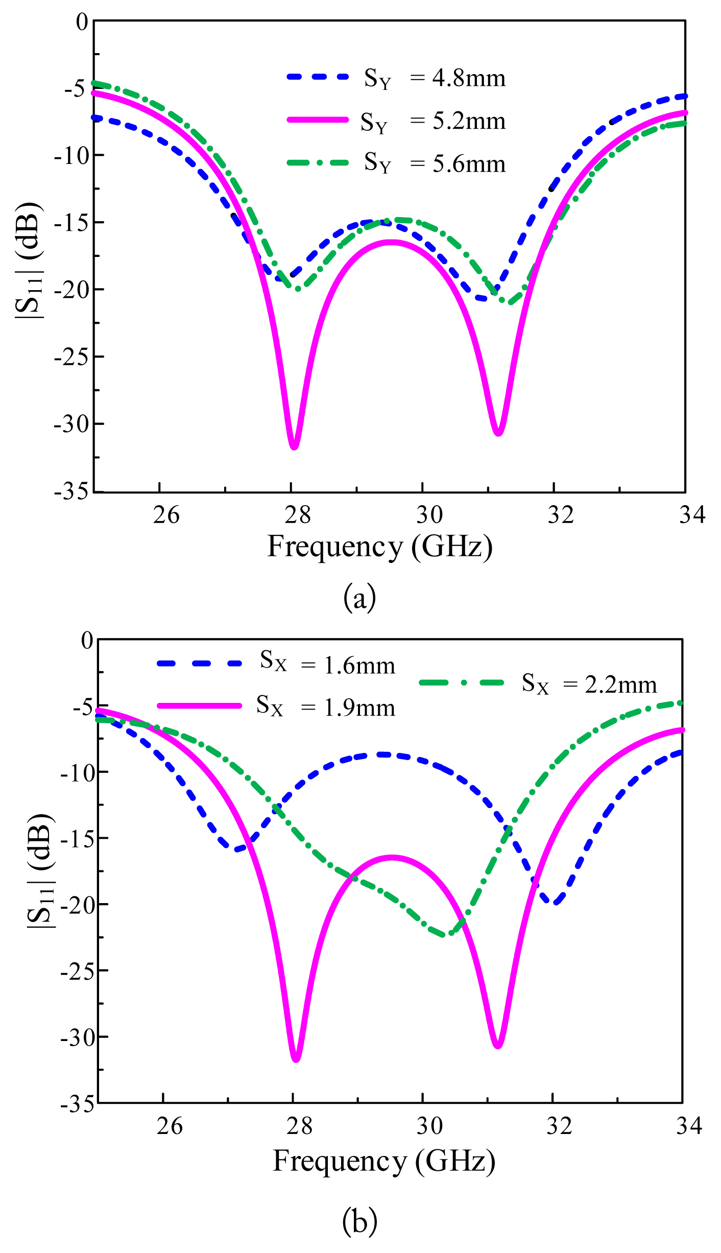
Parametric analysis of the DGS for different values of (a) Gw and (b) GL.
III. Results and Discussion
1. Scattering Parameters
The prototype was fabricated using a standard chemical etching process, and a 2.92 mm endlaunch connector (Southwest Microwaves Inc., Tempe, AZ, USA) was used to feed the antenna. The simulated reflection coefficient plot for the proposed antenna (Fig. 4) illustrates that a wide frequency band of 26.6–33.2 GHz was obtained with an impedance bandwidth of 6.6 GHz. Further, the measured reflection coefficient curve indicates that an impedance bandwidth of 6.4 GHz (26.5–32.9 GHz) was obtained, which is in good agreement with the predicted value. However, small discrepancies were observed between the simulated and measured results due to imperfections in fabrication and losses across the coaxial cables used for measurement.
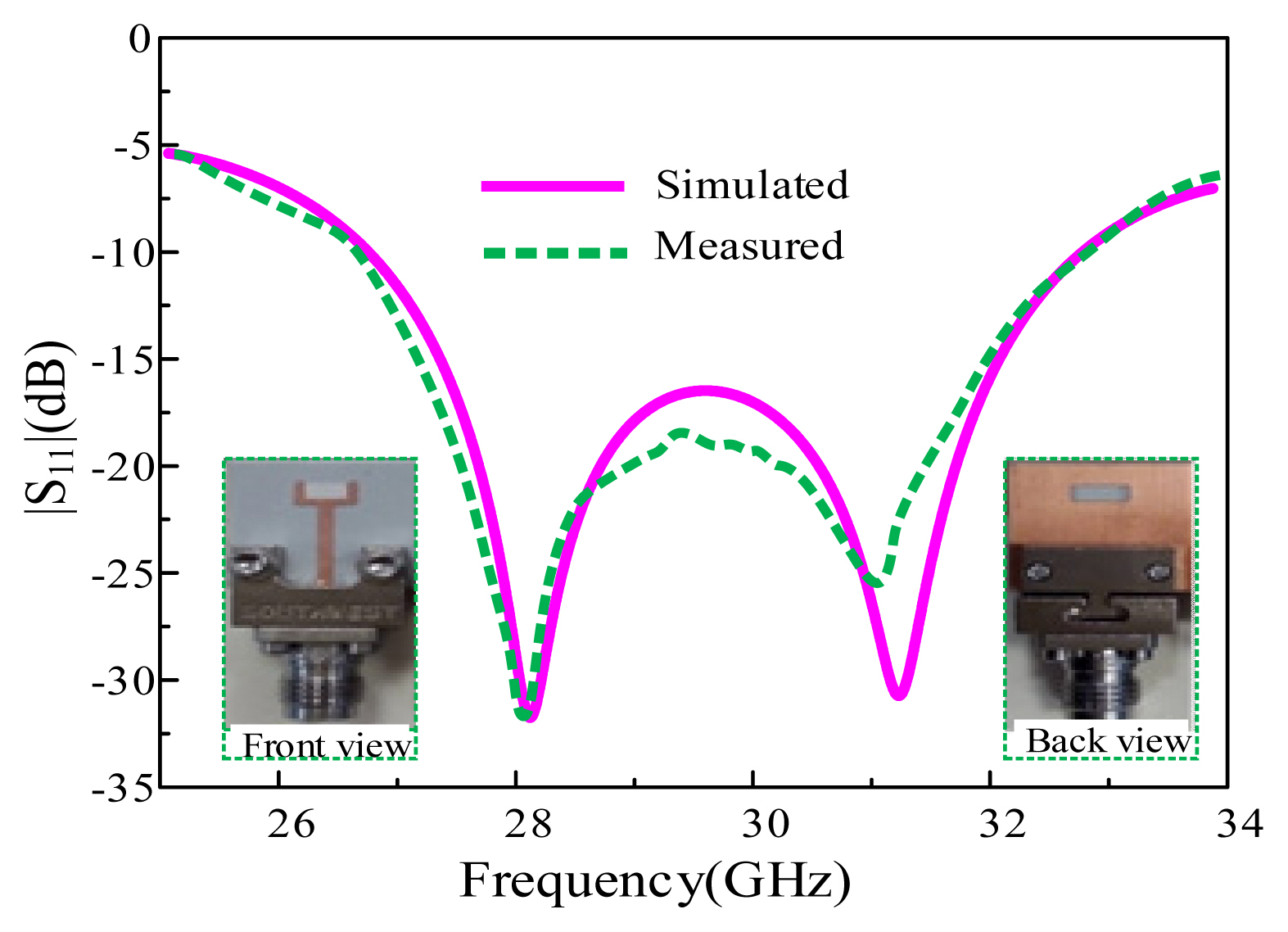
Simulated and measured |S11| of the proposed antenna.
2. Radiation Characteristics
The radiation patterns of the proposed antenna are illustrated in Fig. 5(a) and (b). For both 28 and 31 GHz, the proposed antenna exhibited a bidirectional radiation pattern in the E-plane (Φ = 0°) and H-plane (Φ = 90°), where the maximum power was transmitted at Φ = 0° and Φ = 180°. It should be noted that the patterns in both planes were off bidirectional due to the presence of the radiating slot in the ground plane. It could also be observed that the maximum current distribution was observed along the Y-shaped patch and along the edges of the slot, which resulted in bidirectional radiation patterns of the antenna (Fig. 6). Furthermore, a very low value of cross polarization (greater than −22 dB) was observed at both resonating frequencies. The realized gain and radiation efficiency of the proposed antenna are exhibited in Fig. 7, where it can be observed that the proposed antenna a total efficiency of > 84% in operational bandwidth, and a peak value of 87% was observed at 31 GHz.
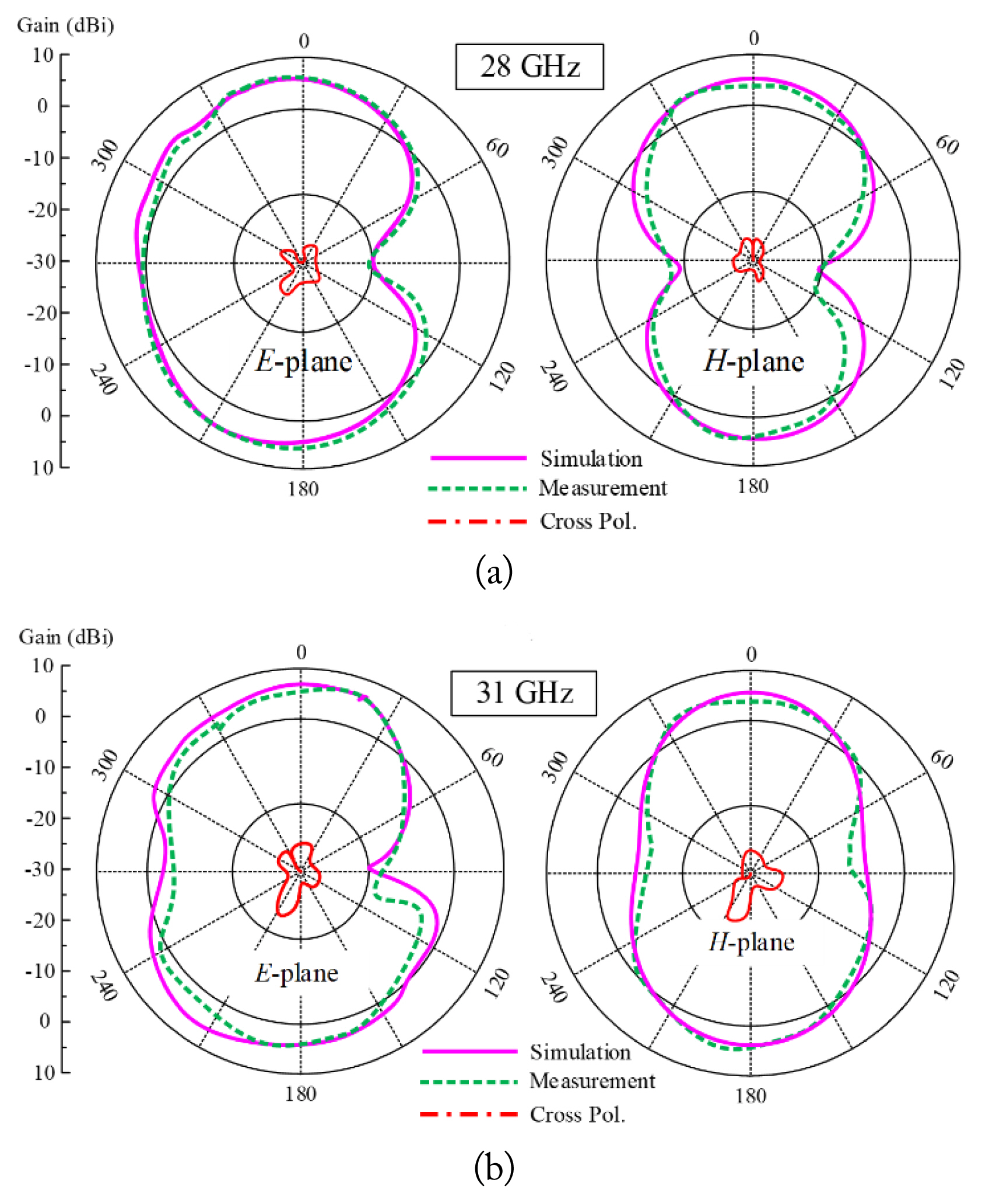
Simulated and measured radiation patterns of the proposed antenna.
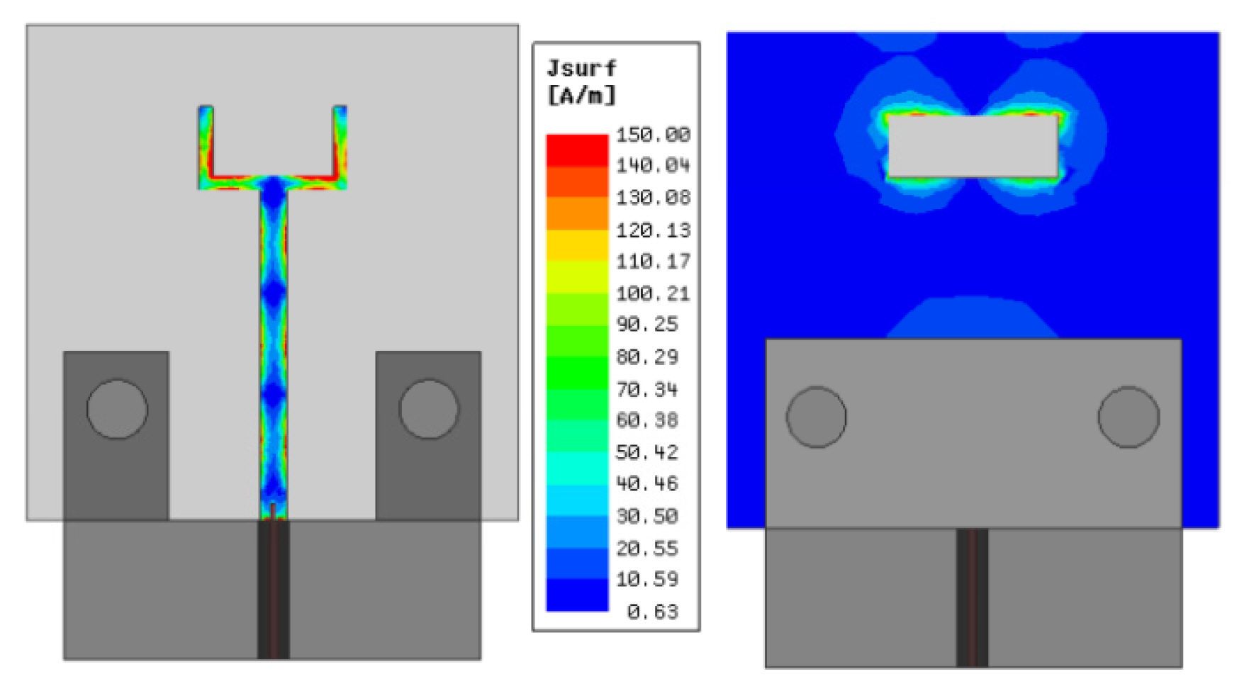
Surface currents of the antenna at 28 GHz.
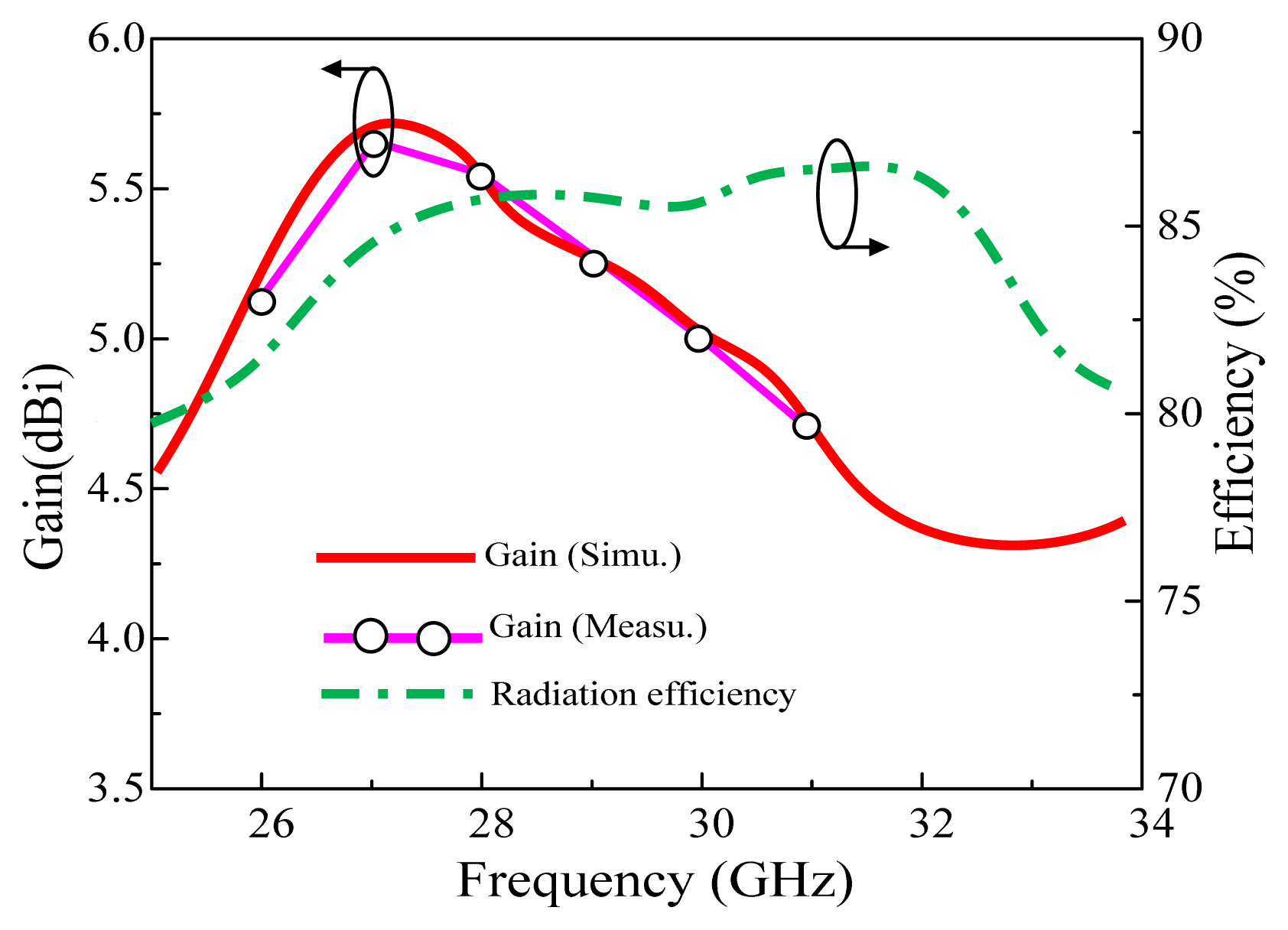
Gain and efficiency of the proposed antenna.
3. Comparison with State-of-the-Art Works
The performance of the proposed antenna was compared with that of the related works reported recently. Table 1 presents a summary of this comparison, considering the key design parameters. It can be observed that the proposed antenna offers a compact size compared to other designs and has the advantages of lower height, wide operational bandwidth, high gain, efficiency, and a simple geometrical structure. Therefore, the proposed antenna is ascertained to be a potential candidate for 28 GHz 5G applications.

Comparison of proposed antenna with related state-of-the-art works
IV. Conclusion
The antenna presented in this paper is a compact wideband printed antenna based on DGS for mm-wave 5G communication applications. The proposed geometry utilizes the benefits of DGS for achieving miniaturization (lowering the resonant frequency) and to obtain wideband operation with stable radiation characteristics. The antenna achieved a measured −10 dB |S11| bandwidth of approximately 6.4 GHz (ranging from 26.5 to 32.9 GHz) with a peak gain of 5.62 dBi. The compactness of the structure and its wide bandwidth ensure the suitability of the proposed antenna for impending 5G communication systems.
References
Biography

Wahaj Abbas Awan received his B.S. degree in Electrical Engineering from the COMSATS University Islamabad, Sahiwal Campus, in 2019. He is currently pursuing an M.S. degree in integrated IT engineering at the Seoul National University of Science and Technology, Seoul, South Korea, where he is also a research assistant with the Electromagnetic Measurement and Application (EMMA) Laboratory. He is the author of more than 25 peer-reviewed conference and journal articles with research interests that include electrically small, flexible, and reconfigurable antennas.

Syeda Iffat Naqvi received her B.Sc. Engineering degree in Computer Engineering and M.Sc. degree in Telecommunication Engineering from the University of Engineering and Technology, Taxila, Pakistan, in 2006 and 2011, respectively. She is currently serving as an Assistant Professor at the University of Engineering and Technology, Taxila. She is working toward the design and implementation of multiple antenna array systems for current 4G and next generation mm-wave 5G applications.

Aqeel Hussain Naqvi received his B.S. degree in Electrical (Telecommunication) Engineering from COMSATS Institute of Information Technology (CIIT), Islamabad Pakistan, in 2011, and an M.S. degree in Electrical (RF and Microwave) Engineering from the School of Electrical Engineering and Computer Sciences (SEECS), National University of Sciences and Technology (NUST), Islamabad, Pakistan, in 2015. He is currently pursuing a Ph.D. in the School of Electrical and Electronics Engineering, Chung-Ang University, Seoul, South Korea. His research interests include the design and analysis of microwave and mm-wave antennas, reconfigurable antennas, and planar and 3D printed antennas.

Syed Muzahir Abbas received his B.Sc. degree in electrical (telecommunication) engineering from the COMSATS Institute of Information Technology (CIIT), Islamabad, Pakistan, in 2006, the M.Sc. degree in computer engineering from the Center for Advanced Studies in Engineering (CASE), Islamabad, Pakistan, in 2009, and the Ph.D. degree in electronics engineering at Macquarie University, North Ryde, Australia, in 2016. He has worked as a transmission engineer for Alcatel-Lucent, Pakistan, an RF engineer with CommScope, Australia, and as a senior antenna design engineer with Benelec Technologies, Australia. He has lectured various courses at CIIT, Islamabad, Pakistan, and in Australia at Western Sydney University, Macquarie University, and the University of Sydney. Currently, he is working as a senior principal engineer with Benelec Technologies, Australia. He has been a visiting researcher at ElectroScience Laboratory, Ohio State University, USA, and Queen Mary University of London, UK. He has also received several prestigious awards and fellowships, including the 2019 IEEE NSW Outstanding Young Professional Award, the 2018 Young Scientist Award (Commission B - Field and Waves) from the International Union of Radio Science (URSI), the 2013 CSIRO Postgraduate Fellowship, the 2012 iMQRES Award for Ph.D., and the Research Productivity Awards in 2012 and 2010 from CIIT, Pakistan. His research interests include base station antennas, mm-wave antennas, high-impedance surfaces, frequency selective surfaces, flexible/embroidered antennas, CNT yarns, CNT/graphene-based antennas, reconfigurable antennas/electronics, and the development of antennas for UWB and WBAN applications.

Abir Zaidi received her master’s degree in microelectronics, telecommunication, and industrial data processing at the same university. She is currently a Ph.D. student at the Laboratory of Electronics, Energy, Automatics and Data Processing (EEA&TI) Hassan II University, Mohammedia-Casablanca, Morocco. Her studies and interests are focused on the design of multiband microstrip patch antennas to operate in the 5G and mm-wave bands.

Niamat Hussain received an M.S. degree in electrical and computer engineering from Ajou University, Suwon, South Korea, and a Ph.D. degree in information and communication engineering from Chungbuk National University, Cheongju, South Korea. He received the best paper award in 2017 for his paper presented at the Korea Winter Conference (KIEES). He is also the recipient of Outstanding Graduate Researcher Award and have authored/co-authored more than 40 international journal papers. Currently, he is a postdoctoral researcher at Chungbuk National University. His research is mainly focused on lens-coupled antennas, metasurface antennas, metamaterial antennas, UWB antennas, mm-wave antennas, and terahertz antennas.