I. Introduction
Missile accuracy is directly affected by the performance of the radar mounted on the missile. On a large missile, an array of slot antennas or a patch antenna structure is typically used for the missileŌĆÖs radar [1ŌĆō3]. Antennas with this type of structure are generally mounted with a phase shifter on the back end of the antenna, which tracks and intercepts an object by modifying the beam directing angle. Since such systems are large and relatively expensive, they are not suitable for mounting on a small missile for tracking a small object. Instead, a semi-active-type radar, which only has a receiver module, is employed on small missiles [4].
Among such semi-active-type radar systems, one of the representative antenna designs applied to the surfaces of small missiles is the sub-wavelength-aperture monopulse conformal antenna patented by Lockheed Martin [5]. This antenna is produced by modifying a bullŌĆÖs eye antenna, and to control the missileŌĆÖs flight direction, the beam angle is steered using a dielectric. Detection is performed by the monopulse method utilizing four antenna arrays on the warhead surface. However, when the beam direction setup is modified in the basic bullŌĆÖs eye antenna, the side lobe level is increased, resulting in a complicated structure and high manufacturing cost [6]. In [7], patch antenna used for the transmission and reception module can also be mounted on the sharp and the structure is simple, the missile surface. Although the beam is sharp and the structure is simple, the antenna beam direction does not match the missileŌĆÖs travel direction. Therefore, this is inadequate for use as an antenna for a monopulse radar.
In this study, a position tracking antenna is proposed for use in such radar systems, by using a printed monopole Yagi-Uda antenna that can be mounted on the warhead of a small missile. The antenna can be manufactured by a simple method, and the cost of manufacturing is low. In addition, the beam pattern can be easily modified, and the gain can be easily improved by using a reflector and a director. Moreover, since its shape is easily changed, a printed monopole Yagi-Uda antenna can be easily mounted on the surface of a missile warhead. The typical printed Yagi-Uda antenna uses ╬╗/2 dipole as driven elements [8, 9]. Such a structure requires a balun or an additional ground on the dipole, resulting in a complex or large structure. To solve this problem, we studied a new structure in which the feeding element is a monopole [10ŌĆō18], which has the symmetry pattern in the broadside direction. However, while this had a simpler structure than the existing Yagi-Uda antenna, it is not suitable for use as a monopulse because the beam does not point in the endfire direction due to the ground effect. To overcome these shortcomings, we proposed a printed Yagi-Uda antenna that can be used as a monopulse radar antenna by applying a ╬╗/2 director to a missile warhead.
II. Antenna Design
Fig. 1 shows the design structure of the antenna proposed in this study. Fig. 1(a) shows the structure with the front part removed in the antenna proposed in [10]. This is to align the beam direction with the missileŌĆÖs travel direction. The antenna director shown in Fig. 1(a) did not perform properly. To solve this problem, a ╬╗/2 director is proposed, as shown in Fig. 1(b). The director attached to the ground was manufactured with a 0.5 mm gap from the ground. The structure shown in Fig. 1(c) is the four-array version of the structure shown in Fig. 1(b).
Fig. 1(d) shows the three-dimensional shape of the structure mounted on a warhead. The diameter of the bottom surface of the conical warhead was determined to be 29 mm. The antenna was attached to the back end in order to keep the beam direction of the antenna aligned with the missile direction.
Fig. 2 shows the change in gain at 0┬░ when the length of the director of the Fig. 1(c) antenna is swept. Below 0.4╬╗, it can be seen that the gain increases as the length of the director increases. Above 0.4╬╗, it can be seen that the gain decreases as the length increases. This is because when the element length becomes larger than a certain length, it operates as a reflector rather than a director. Therefore, in this study, a director of 0.4╬╗ length was designed with the maximum gain. Moreover, the gain change was simulated by changing the distance from the driven element from 0.5 to 2.5 mm in 0.5 mm increments. As a result, the difference between the maximum and minimum values was 0.33 dB. Accordingly, it was confirmed that the distance between the ground and the director does not have a significant effect on gain.
Fig. 3 shows the structure of the manufactured antenna. Coated paper was attached to both sides of the antenna to realize curvature. Two of the antennas are used to detect the vertical plane, while the other two are used to detect the horizontal plane.
III. Simulated and Measured Results
Fig. 4 shows the simulated (CST Studio Suite, https://www.cst.com) current distribution of the antennas shown in Fig. 1(a) and (b). Fig. 4(a) shows that the current of the director does not flow independently and flows along the ground and does not act as a director. In contrast, the current flow shown in Fig. 4(b) reveals that the current of the director flows in the direction opposite to the feed and operates normally as a director.
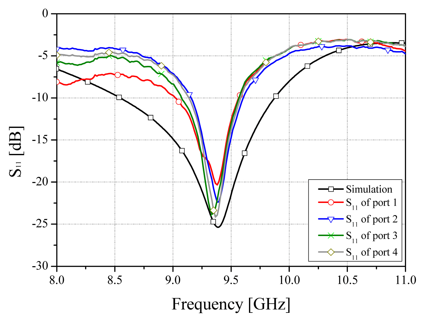
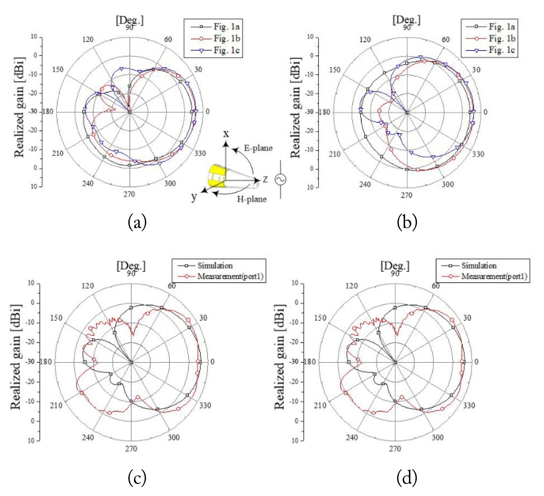
Fig. 5 shows the comparison between the S11 simulation value and the S11 graph of the four ports of the manufactured antenna. Both simulation and measurement values had excellent matching characteristics of ŌłÆ20 dB or more at 9.375 GHz. The measured bandwidth was slightly narrower than the simulated bandwidth of 1,332 MHz, because the ground height of the manufactured antenna was larger than that in the simulation. As the area of the ground plane increases, this effect decreases relatively and thus the tendency of bandwidth increase decreases significantly as the ground plane effect is enhanced. In Fig. 6(a) and (b), the radiation patterns of the Fig. 1(a)ŌĆō(c) antennas are compared and shown. When changing from the director structure in Fig. 1(a) to the director structure in Fig. 2(b), the 0┬░ gain increased by 1.58 dBi from 4.36 dBi to 5.94 dBi. The four-array structure shown in Fig. 1(c) showed an even better gain of 6.24 dBi. Fig. 6(c) and (d) show the comparison between the simulation and the measured values. Result showed that the front beam pattern and gain were similar. Other directions had different beam patterns, which are considered to be different in the feeding method of simulation and measurement. Table 1 shows the comparison of maximum gain between the simulation and measurement. It can be seen that all four ports have gains similar to the simulation.
IV. Conclusion
In the present study, a four-array antenna was proposed for a small missile radar that can be mounted on a conical warhead. The antenna adopts the printed Yagi-Uda antenna as the basic structure to solve the complex structure, which is the disadvantage of the general Yagi-Uda antenna. In addition, a ╬╗/2 director was applied to improve the beam direction, which is a disadvantage of the printed monopole Yagi-Uda antenna. Unlike the existing structure, the director is positioned in front of the ground so that current flows independently and can function as a director. As a result of the design, S11 has excellent matching characteristics of ŌłÆ20 dB or more at the center frequency of 9.375 GHz in the simulation and manufacture. In addition, in the case of the radiation pattern, it has a characteristic that is directed in the same direction as the missile travel direction, and in the case of gain, both simulation and production values have excellent performance of 6 dBi or more. As a result of the design, the simulation has a maximum gain of 6.24 dBi, and the manufactured antenna has a similar gain of 6 dBi or more. For this reason, the antenna proposed in this study can be mounted on a missile warhead and used as an antenna for radar.