I. Introduction
The radar system mounted on an airborne platform operates in an air-to-ground mode as well as in an air-to-air mode [1]. For example, the AN/APG-77 is the F-22’s primary sensor that provides several functions, including terrain mapping, ground-moving target searching/tracking, and air-to-ground ranging (AGR) [2]. The AN/APG-77 radar adopts a monopulse system with an active electronically scanned array (AESA) antenna. The amplitude-or phase-comparison monopulse radar transmits one pulse and then receives three monopulse channels as the sum, elevation, and azimuth difference channels. The channels are calculated as three weighted sums of partial signals received by each antenna element in a receiving mode [3, 4]. Also, in the air-to-ground mode, the clutter backscattering may become much stronger than that of the air-to-air mode, and such strong backscattering can seriously degrade the radar’s performance [5].
The radar echo signals are determined by basic radar radio frequency (RF) specification, such as frequency and pulse repetition interval (PRI), etc., and the radar’s operation environment, such as platform dynamics, ground clutter type, antenna foot-print on the ground plane (mainly determined by the platform orientation), and the ASEA antenna’s beam illumination. Due to the dynamics of the platform and ground clutter, the received signal is slightly distorted, which can be modeled by considering the Doppler frequency shift. Since the range-Doppler (RD) map clearly shows the Doppler frequencies, RD-processing is crucial in many radar applications, including a synthetic aperture radar (SAR) [6] and a moving target indicator [7]. Hence, the modeling of the radar echo signal in a time-domain is required when considering the effect of all the aforementioned factor’s needed to generate an accurate RD map.
Much attention has been paid to the backscattering determined by the ground clutter, which can be used to determine the mean power received by the radar. Since the clutter signal is a typical random signal, several probability density functions (PDF) have been used, such as Gaussian, Weibull, K-distribution, and so on [8]. Except in the case of sea clutter, the Gaussian distribution is a simple and accurate way to develop a time-domain signal model [9]. The correlated Gaussian random signal can be generated in a relatively easy and accurate manner [10, 11], and is a conventional method for incorporating the Doppler effect of the clutter into the modeling of pulse-Doppler radar signals [12].
In Section II, we address the proposed modeling approach of the radar echo signal for a phase-comparison monopulse radar [3], considering the Doppler effects due to the dynamics of the platform and the ground clutter simultaneously. Section III presents the numerical results for operating scenarios that consider the platform dynamics and antenna beam steering direction, etc. Finally, an AGR simulation is examined for a real-world application.
II. Modeling Method
1. Scenario and Coordinate Systems
The dynamic scenario for the air-to-ground radar operation is shown in Fig. 1. An airborne platform moves at a constant velocity, v⃗ = vxx̂ + vyŷ + vzẑ, while repeatedly transmitting a signal to the ground surface at every PRI. Given that an antenna beam is illuminated toward the line of sight (LOS), the return signals may be reflected primarily from the main-lobe beam projected on the ground that is truncated by the half-power beam width (HPBW) for a numerical simulation. The return signals of multiple pulses are aligned along the fast time (t) and the slow time (η), generating 2D raw signals [13]. The mean reflection power from the ground clutter inside the projected main-lobe beam can be calculated using the backscattering coefficient [14]. Here, we assume the ground clutter to be a rough surface [15] for which a theoretical backscattering model, such as an Integral Equation Model (IEM) may be accurate [16] for two co-polarized scatterings. The return signal can be assumed to be a Gaussian random signal whose backscattering coefficient is used as a variance of the random signal. The movement of the platform and ground clutter can be modeled using the Doppler frequency shift in the received signals.
Note that the shape of the projected main-lobe beam in Fig. 1 is dependent on the orientations of the platform and the antenna. Hence, the coordinate systems of the platform and the antenna are important. The relationship between the global and local coordinate systems of the platform is shown in Fig. 2. The parameters related to the coordinate systems in Fig. 2 are summarized as follows:
As the local coordinate of the antenna coincides with that of the platform, ŝl is defined as
Considering the dynamics of the platform, the LOS vector of the antenna in the global coordinates is rotated depending on θr θy and θp as seen in Fig. 2. Based on θr θy and θp: the antenna’s LOS vector in the global coordinate, ŝg, is represented as
where Rx, Ry, and Rz are rotation matrices along the global x, y, and z axes, respectively [17]. In Fig. 3, the signs of the antenna weights for three monopulse channels are defined. The V and W axes of the monopulse radar coincide with the yg and zg axes in the global coordinates, respectively [18]. In Figs. 4 and 5, the projected main-lobe beam and the V and W axes are found on the ground plane using a ray-tracing technique: first, the normal vector of the antenna’s VW plane is aligned in the direction of ŝg. Then, rays are launched from the antenna’s center to the rim of the HPBW of the antenna pattern or the V and W lines in the antenna’s VW plane. Finally, the intercept points between the rays and the ground plane are calculated.
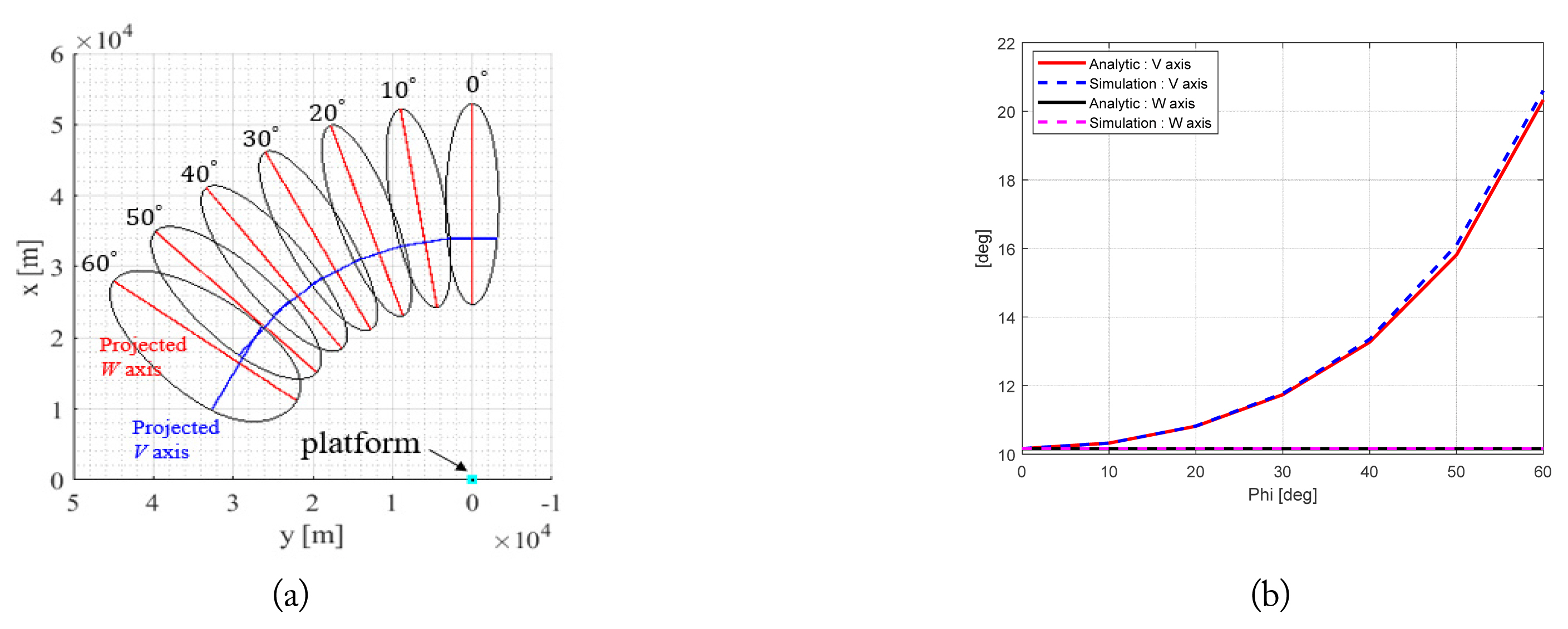
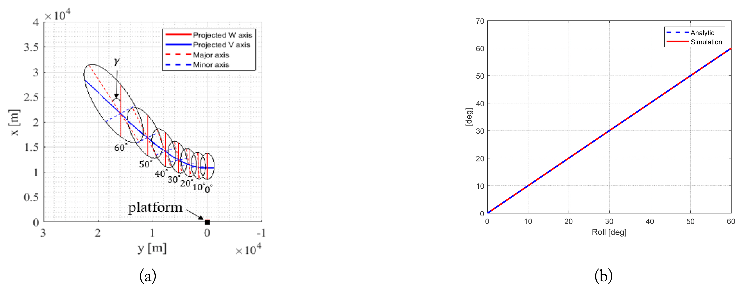
The simulation parameters are presented in Table 1. In Fig. 4, the platform orientation and antenna beam steering are given as θr = 0º, θy = 0º, θp = 0º, and θ = 105º, ϕ = 0º–60º, respectively. As observed in Fig. 4(a), it is well-known that as the azimuth angle (ϕ) increases, the HPBW of the V axis broadens while the HPBW of the W axis remains constant [19]. The simulation and theoretical estimations for the HPBW of the V and W axes on the ground are compared in Fig. 4(b), where an excellent agreement can be observed. As shown in Fig. 5(a), if the platform is rolled, the monopulse axes rotate by a small angle, γ, with respect to the major axes parallel to the LOS vector [14]. The estimations of γ by simulation and by the known theoretical formula [14] are in excellent agreement, as seen in Fig. 5(b). For this calculation, the platform orientation angles are assumed as θr = 0º–60º, θy = 0º, and θp = 0º. The beam illumination angles of the antenna are fixed at θ = 130º and ϕ = 0º. Therefore, the projected antenna footprint on the ground plane can be accurately found for any platform and antenna orientation.
2. Radar Return Signal in a Time-Domain
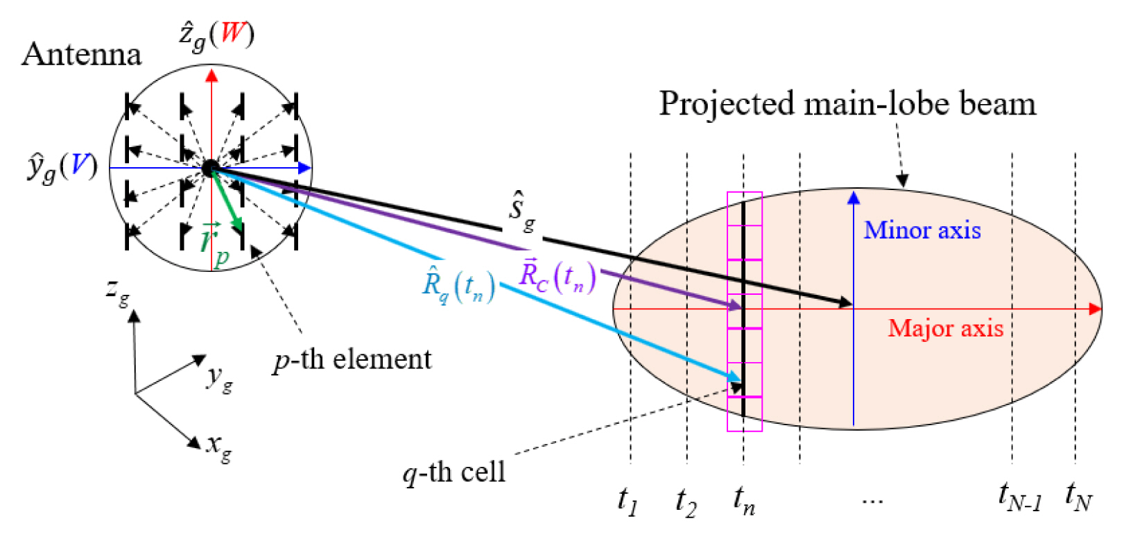
The configuration of the signal transmission/reception at the radar and the corresponding projected main-lobe beam needed to calculate the radar return signals in a time-domain are shown in Fig. 6. First, the projected main-lobe beam is divided into uniform rectangular grids (cells) based on a preset range resolution. The range resolution is determined using the sampling time interval of the fast time (t) [13]. The projected area can be approximated as an ellipse [20] whose major axis is parallel to the LOS direction from the radar to the center of the ellipse. Since the minor axis is perpendicular to the major axis, the ellipse can be uniformly discretized using a rectangle along the major and minor axes, as seen in Fig. 6. The ellipse is located in the far-field region from the platform, and so the return signals from the cells along a line parallel to the minor axis are coherently added into one time-domain response in each sampling time (range bin). The received monopulse signals from each q-th ground cell is represented as
(1)
where σq and A(q) are the backscattering coefficient and area of the q-th cell, respectively, G is the gain of the antenna element, and δ (·) is the Dirac delta function. Note that the q-th cell belongs to the sampling time (tn), as shown in Fig. 6. The sampling time can be computed simply as tn = 2Rc (tn, η)/c, where c is the speed of light. Rc (tn, η) is the distance from the platform to the q-th cells corresponding to the major axis, as shown in Fig. 6. AF∑, AFΔEL, and AFΔAZ are the array factors of the antenna for the sum, elevation difference, azimuth difference channels, respectively, on the q-th cell, which is given as
(2)
where Np is the number of the antenna elements and k0 is the free-space propagation constant. R̂q (tn, η) is the direction vector from the phase center of the antenna to the q-th cell at t = tn · ⇉p is the displacement vector from the phase center of the antenna to the p-th antenna element.
w p Σ , w p Δ E L w p Δ A Z
where Ψ∑, ΨΔEL, and ΨΔAZ are the total radar return signals for the monopulse sum, elevation difference, and aizumuth difference channels, respectively.
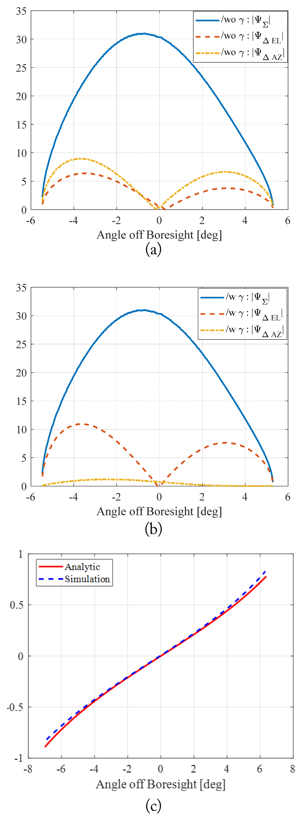
In Fig. 7, the return signal is calculated from a flat ground whose backscattering is assumed to be a constant at a slow time, η = 0. In Fig. 7(a) and 7(b), the platform orientation and antenna beam steering are assumed as θr = 60º, θy = 0º, θp = 0º, and θ = 130º, ϕ = 0º, respectively. The “/w γ” and “/wo γ” indicate “with γ-correction” and “without γ-correction”, respectively. In Fig. 7(a), the roll angle is not zero, so it can be observed that the null of ΨΔEL locates off the boresight and the monopulse response of ΨΔAZ is not zero. But, as shown in Fig. 7(b), when the return signal is compensated with the known γ-correction scheme, the null point of ΨΔEL is shifted to the boresight and the level of ΨΔAZ is decreased to almost zero [4]. The exact and simulated monopulse ratios, Im(ΨΔEL )/Re(Ψ∑), are compared in Fig. 7(c) for θr = 0º [14]. The proposed signal-generation scheme can provide an accurate monopulse ratio. The Re(Ψ∑) is approximately 2 × 10⁻¹⁹, which is essentially zero. Here, Re(z) and Im(z) are the real and imaginary parts of z, respectively. Therefore, the generated time-domain signal can provide accurate monopulse signal behaviors.
3. Doppler Effects
There are two dominant Doppler effects in the dynamic situation considered here because of to the movements of the platform and ground clutter. The Doppler shift of the clutter can be included simply by generating the correlated Gaussian random variable of σq (tn, η) in the slow time in (1) for a proper correlation function, such as the Gaussian and exponential functions. Here, the Cholesky decomposition method is used [11]. The correlation time (tc) is inversely proportional to the Doppler frequency of the ground clutter [21, 22]. After computing (1) with the correlated σq (tn, η)along the slow time, the Doppler shift due to the platform dynamic is considered. The time-dependent distance between the platform and the q-th cell is expressed at the slow time (ηm) as
where (xf, yf, zf ) and (xq, yq, zq ) are the coordinates of the platform and the center of the q-th cell at (t = 0,η = 0) of the global coordinates, respectively. By using the Taylor series expansion, the Doppler frequencies along the fast-time, fD, tn, and slow-time, fD, ηm axes, can be formulated as
where λ0 is the free-space wavelength. Finally, the total return signal, including the Doppler effect due to platform movement, is given as
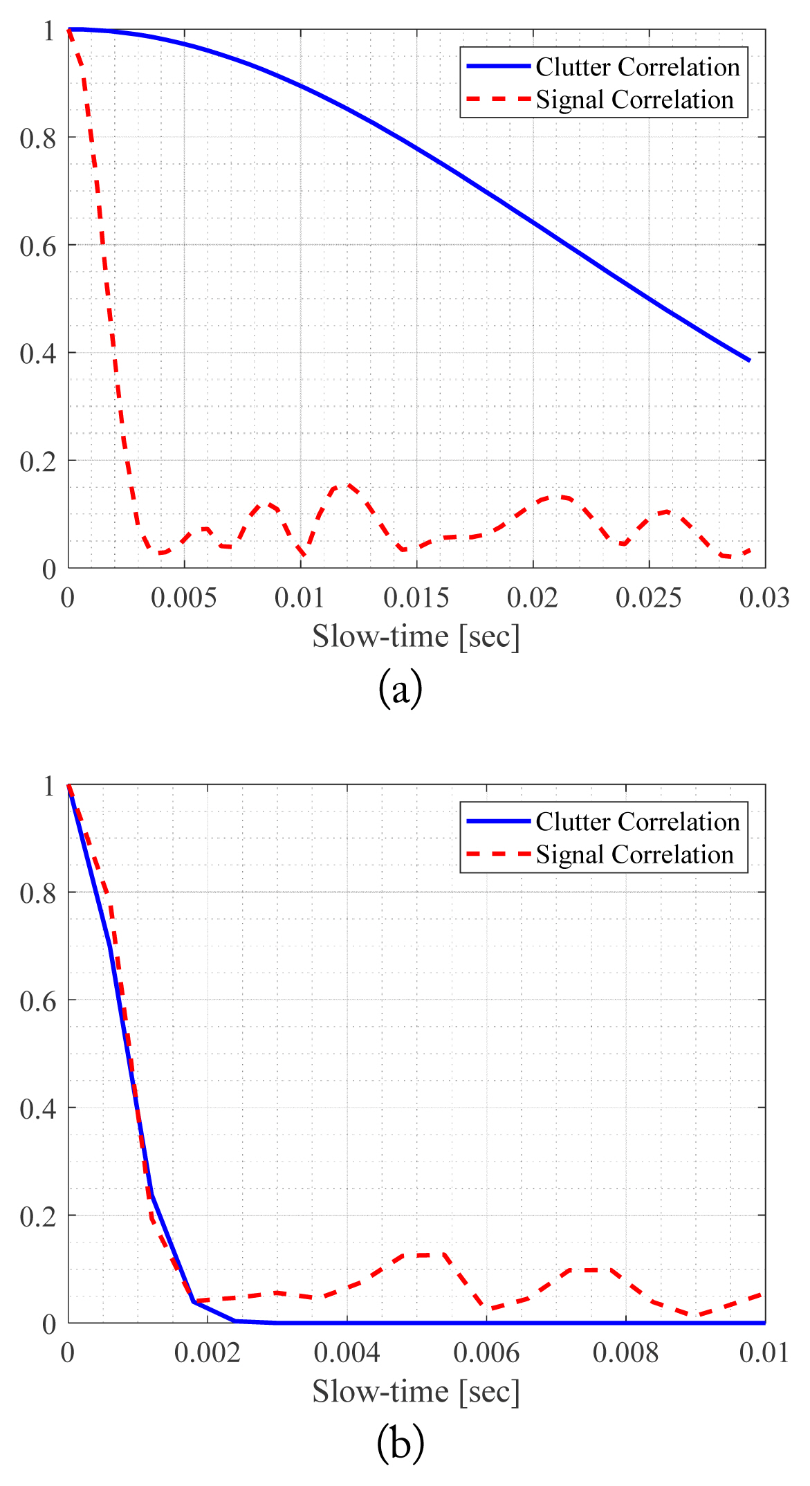
If two Doppler effects are considered at the same time, it is physically expected that the correlation time of the generated signal may be similar to the shorter one between the correlation times due to the platform and clutter dynamics.
III. Simulation Results
The simulation parameters are summarized in Table 1. The parameters of correlation length, root mean square (RMS), and dielectric constant of the rough surface are found in [5]. The pulse repetition frequency (PRF) is the reciprocal of PRI. A complete signal generation is considered, including two Doppler effects. For the rest of the simulations, the platform orientation and antenna beam steering are set as θr = 45º, θy = 0º, θp = 0º, and θ = 130º, ϕ = 0º, respectively. In Fig. 8, the RD maps are shown for the sum and elevation difference signals. The RD map is calculated by taking the fast Fourier transform (FFT) along the slow-time axis, which clearly shows the signal Doppler frequencies. The correlation time of the clutter is assumed as 0.03 seconds for an X-band ground clutter [25]. The Doppler frequency can be exactly computed as 9,192.5 Hz at the center of the projected ellipse. The signal Doppler frequencies on the projected antenna footprint distributes over the wrapped Doppler frequency range (−800 < fD < −700) ∪ (344.6 < fD < 800) [19]. Hence, the correct Doppler frequency generation is observed in Fig. 8. In Fig. 8(b), the null of the elevation signal can be observed. In the Tx mode, only the sum pattern is transmitted, and so the Doppler frequency distribution of the difference pattern is similar to that of the sum pattern. Over the projected antenna footprint on the ground, the Doppler frequencies exit over a 500-Hz band, which indicates that the 500-Hz frequency band is generated due to the platform dynamics. Hence, the correlation time of the return signal due to the platform movement is around 1/500≈0.002 seconds [22, 24]. Thus, two correaltion times of the ground clutter is chosen: a longer correlation time, 0.03 seconds, and a shorter one, 0.001 seconds. As explained earlier, the correlation time of the generated radar signal should be similar to the shorter one between the correlation times due to the platform and clutter dynamics. In Fig. 9, the correlation of the generated signal is computed along the slow time to produce two correlation times of the clutter. It shows that the correlation time becomes the shorter one between the two values of tc of the gound clutter and the platform.
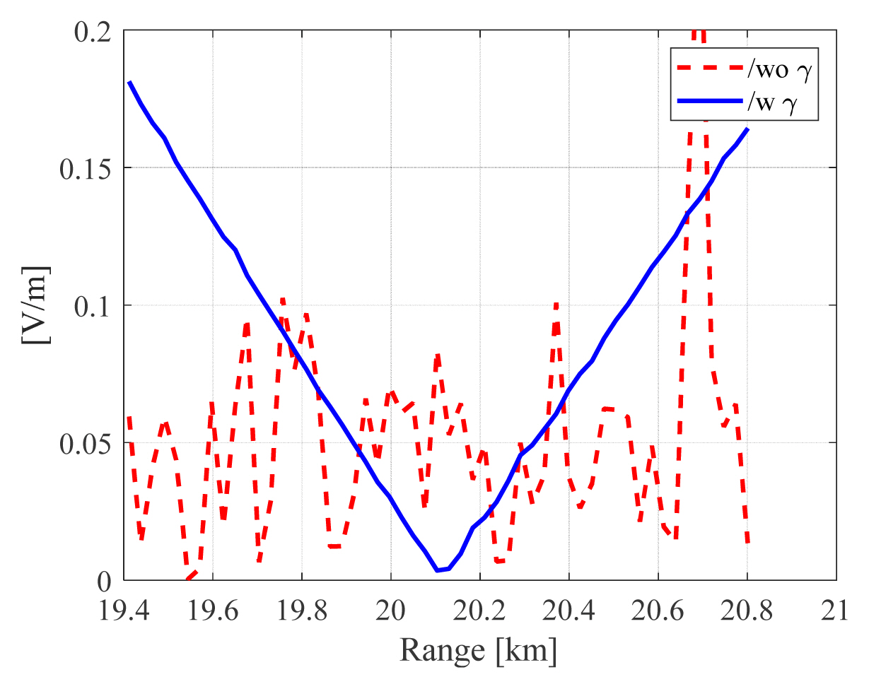
Next, an AGR simulation is considered for a real radar application. Here, we use the coherent integration technique to combine the 2D time-domain signal [26]. The coherent technique truncates the RD map of the sum signal around the Doppler center. Also, the RD map of the elevation difference signal is chosen from the same range as that for the sum pattern. Then, the monopulse ratio is calculated and averaged to one ratio [14, 26]. In Fig. 10, the ratio is shown with and without a γ-correction scheme. The γ-correction scheme can retrieve the correct monopulse ratio, which enhances the accuracy of the range estimation. The null point of the monopulse ratio is around the range estimation [26]. Without the γ-correction scheme, the range estimation error is about 2.06% but with the γ-correction scheme, the error is drastically reduced to about 0.07% which is within the known error range(< ≈ 1%) of the phase-comparison monopulse AGR scheme [14].
IV. Conclusion
A numerical algorithm was proposed to generate the ground return signal in a time domain for a monopulse radar system, which can accurately consider the radar operation scenario and the Doppler effects due to the movements of the platform and ground clutter. To truncate the return area, the main beam up to the HPBW is projected on the ground surface. Since the projected antenna footprint is estimated using a ray-tracing technique, the accuracy of the footprint can be very high for any radar operation scenario. To simulate the monopulse system, the sum signal is transmitted and then, using the appropriate array weights, the sum and two difference signals are synthesized. This method guarantees the correlation relationship between the sum and difference signals from an identical ground cell. The backscattering coefficient of the ground clutter is assumed to be a Gaussian random process. Thus, the Doppler effect of the ground clutter can be efficiently modeled using a correlated random number generation. For an application example, an AGR simulation is considered. The proposed signal-generation method is applied to a monopulse AGR simulation. It is numerically shown that with the known γ-correction scheme, the signal distortion caused by rolling of the platform can be effectively removed. The range estimation error is within the known error boundary for the phase-comparison monopulse AGR scheme.


