Characteristics of the Angled Printed Dipole Array Antenna with Different Numbers of Dipole Elements
Article information
Abstract
This paper investigated the characteristics of series-fed angled dipole antennas as the number of dipoles increased from one to two, four, and eight. A parallel strip line printed on both sides of the substrate was used to connect angled printed dipoles of the same size in a series with equal spacing. As expected, although the gain increased as the number of dipoles increased, the impedance and gain bandwidths decreased. In addition, as the number of dipoles increased, the half-power beamwidth (HPBW) differences between the xz- and yz-planes decreased and the radiation pattern of the xz-plane became more symmetric. Antennas with one, two, four, and eight-dipole elements in a series were designed, and their peak gains were 5.0 dBi, 7.2 dBi, 9.4 dBi, and 10.4 dBi, respectively. The differences between the xz- and yz-plane HPBWs of the four antennas were 160.4°, 41.7°, 14.2°, and 5.3°, respectively. As the number of dipoles in the antenna increased, the differences between the HPBWs in the xz- and yz-planes decreased.
I. Introduction
The 5G wireless communication systems use the high carrier frequency of low millimeter-wave bands to enhance the rate of data transmission. However, because this use of high carrier frequencies increases propagation loss over distance, the need for a high-gain antenna to overcome this problem has become significant [1–5]. The endfire dipole antenna, which is printed on both sides of a substrate, is widely used in wireless communication systems and consists of a small, simple structure with a wide impedance bandwidth and stable gain [6–9].
However, single-printed dipole antennas exhibit low gain, making them inapplicable for use at high frequencies. The radiation pattern of a single-printed dipole antenna is typically asymmetrical, which causes the beam scanning range to present asymmetrically, making it difficult to use for two-dimensional phased array antennas [10–13]. Metal cavity-backed antenna structures, or Yagi-Uda antenna structures with multiple directors, are used to increase the gain and symmetricity of the radiation patterns [14–22]. Metal cavity-backed antennas have similar half-power beamwidths (HPBWs) in the E- and H-planes of their radiation pattern. Thus, the radiation pattern is symmetrical and the antenna gain is high due to cavity resonance. Nonetheless, metal cavity-backed antennas are heavy and expensive [23]. A Yagi-Uda antenna structure can achieve a high gain and symmetrical radiation pattern at a small size and low price, but its antenna characteristics can be difficult to optimize due to the number of directors is increased [24, 25].
In this paper, we propose an array antenna with a symmetrical radiation pattern and high gain by connecting multiple dipole elements in a series. In the proposed array antenna, several identical dipole elements are connected in a series using parallel strip lines printed on both sides of the substrate. We designed a single dipole antenna, and array antennas with two-, four-, and eight-dipoles and compared their characteristics.
II. Single Dipole Antenna Design and Characteristics
Fig. 1 shows the geometry of the single angled printed dipole antenna with the dipole bent 45° toward the ground plane. Angled dipoles are smaller than straight dipoles and have excellent matching performance. In addition, mutual coupling is low when used as an array [13, 14]. This paper used an angled dipole because of the abovementioned advantages. The detailed design procedure and characteristics of the single-element angled dipole antenna can be found in [14]. The substrate used in the antenna design is a Rogers RO4003C (ɛr = 3.38, tanδ = 0.0027) substrate, and its thickness is 0.2032 mm. Each arm of the single dipole antenna is printed on both sides of the substrate, and the power input through the microstrip line of the truncated ground plane is transferred to the dipole through the parallel strip lines printed on both sides of the substrate. Each dipole is connected by a parallel strip line, and the length of Lq is adjusted so that the impedance of the parallel strip line and the 50-Ω microstrip line match. An ANSYS High Frequency Structure Simulator (HFSS) was used to simulate and optimize a single angled printed dipole antenna, and the design parameters of the optimized antenna were as follows: W = 10 mm, L = 14.8 mm, Lg = 10 mm, Ld = 2.2 mm, Wd = 0.3 mm, S = 2 mm, Sd1 = 2.8 mm, Wr = 0.3 mm, Lq = 1.6 mm, Wq = 0.3 mm, and Wf = 0.5 mm.
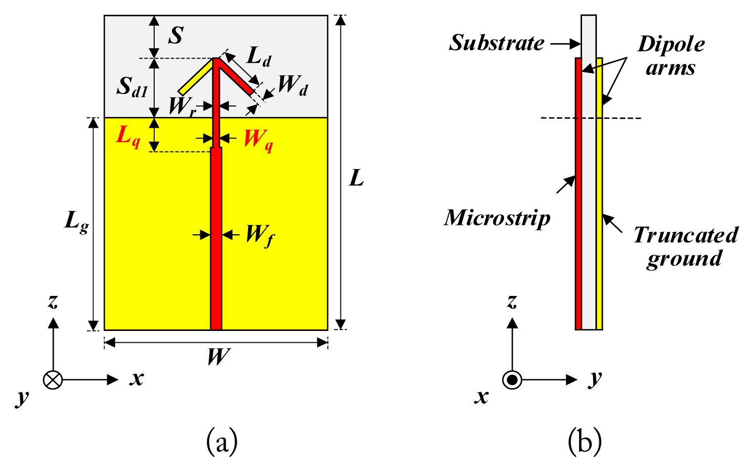
A single-printed angled dipole antenna: (a) front view and (b) side view.
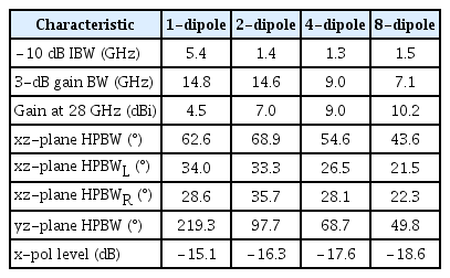
Fig. 2 illustrates the characteristics of a single angled dipole antenna. The −10 dB impedance bandwidth is 25.6–31.0 GHz, and the 3-dB gain bandwidth is 20.1–34.9 GHz. The gain at the center frequency of 28 GHz is 4.5 dBi, and the cross-polarization level is less than −15.1 dB. The HPBWs of the xz- and yz-planes are 62.6° and 219.3°, respectively, and the HPBW of the yz-plane is approximately 157° wider than the HPBW of the xz-plane. Moreover, the radiation pattern of the xz-plane is asymmetrical. In line with the endfire direction, the HPBWs on the left and right sides of the radiation pattern are indicated as HPBWL and HPBWR—with the corresponding angles of 34° and 28.6°—respectively. HPBWL is approximately 5.4° wider than HPBWR. The xz-plane radiation patterns present asymmetrically in a single dipole due to the considerable influence of the truncated ground plane that acts as a reflector. Each arm of the dipole is printed symmetrically on both sides of the substrate; however, the truncated ground plane exists in only some areas on one side of the substrate, making the whole structure asymmetrical. Therefore, the radiation pattern of the xz- plane presents asymmetrically, and the main beam direction is tilted.
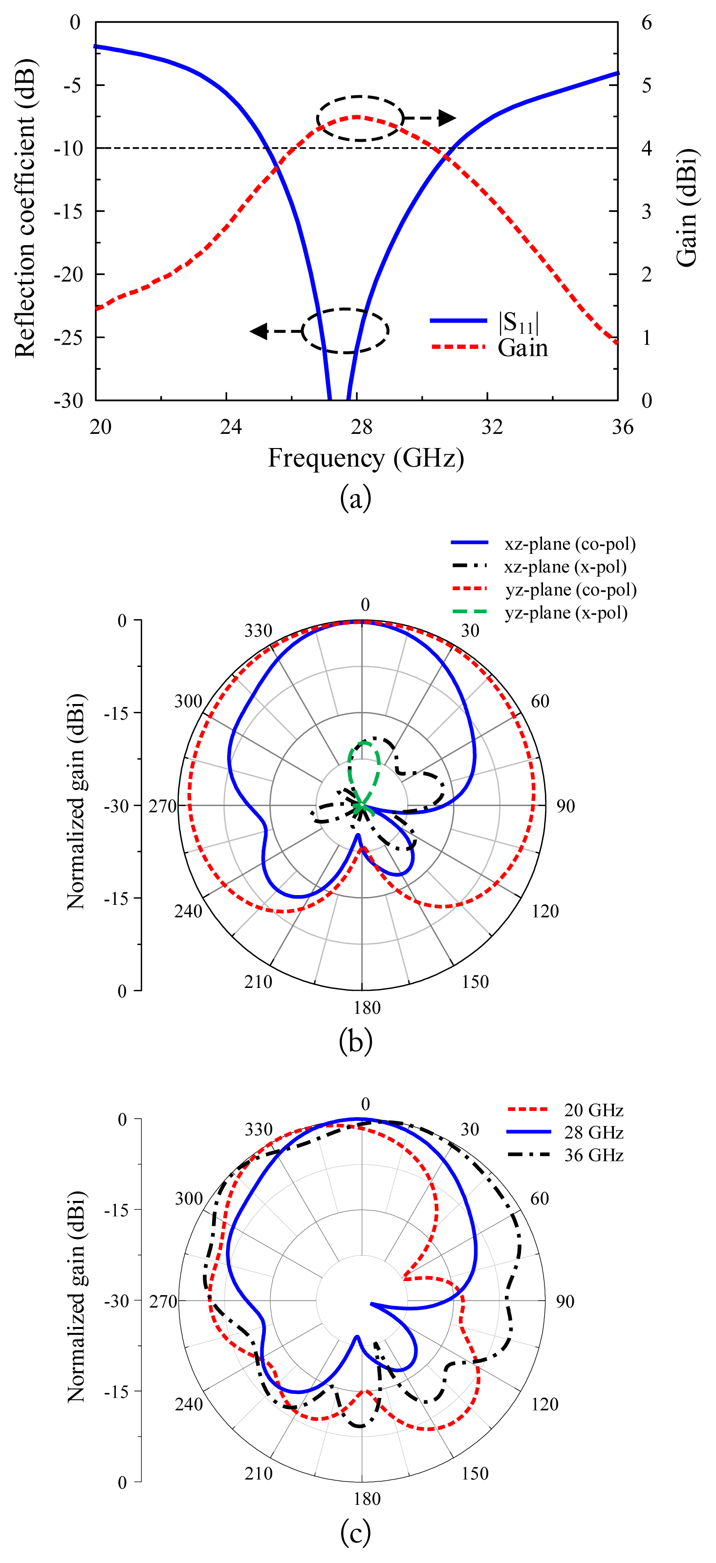
Simulation results of the single dipole antenna: (a) reflection coefficient and gain curve, (b) radiation pattern at 28 GHz, and (c) radiation pattern of the xz-plane at three different frequencies.
III. Series-Fed Dipole Array Antennas
Fig. 3 shows the structure of series-fed printed dipole arrays with dipole elements of the same size as the single-printed dipole antenna above. Two, four, and eight-dipole elements were connected in a series, and the antennas’ characteristics were optimized. The spacing and phase differences between the dipole elements of the series-fed endfire array determine the gain of the array. To maximize the gain of the endfire array, the phase difference between dipole elements must decrease as the number of dipole elements in the array increases [26]. Therefore, the spacing between dipoles, Sd2, was reduced when the number of dipoles of the array increased. The exact value of Sd2, which provides the maximum gain at the center frequency, was obtained through a parametric study. A quarter-wave transformer was used to match the impedance of the 50-Ω microstrip line and the array antenna, and the length, Sd1, of the parallel strip line connecting the first dipole and the microstrip line was adjusted. The Sd2 values of the two-, four-, and eight-dipole element array antennas are 2.8 mm, 2.3 mm, and 1.7 mm, respectively. When expressed in terms of wavelengths, they are 0.26λ0, 0.21λ0, and 0.16λ0, respectively. Table 1 shows the optimized design parameters of the single-printed dipole antenna and the array antennas with two, four, and eight-dipole elements in a series.
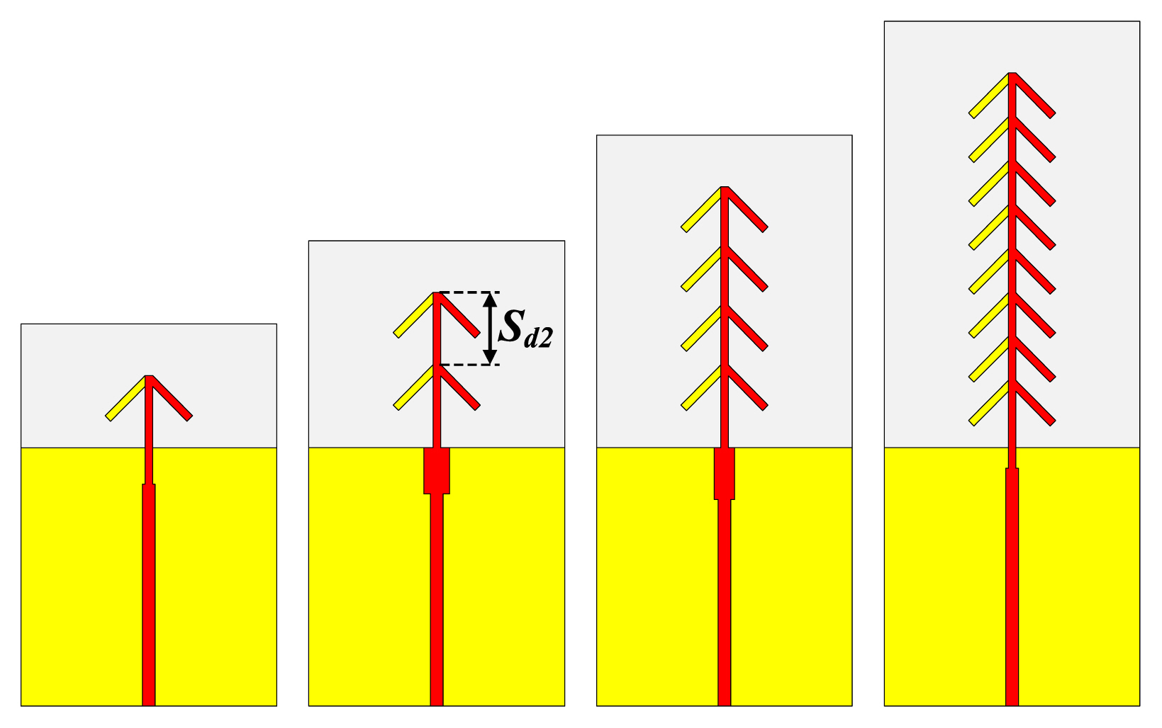
Series-fed array antenna geometry.

Design parameters of antennas
Fig. 4 shows the simulation results for the antenna with one-, two-, four-, and eight-dipole elements. Fig. 4(a) shows the four antennas’ reflection coefficients. When compared to a single dipole antenna, the impedance bandwidth of the array, wherein several dipoles of the same size are connected in a series, is reduced. The impedance bandwidths of the one-, two-, four-, and eight-dipole arrays are 25.6–31.0 GHz, 27.5–28.9 GHz, 27.6–28.9 GHz, and 27.8–29.3 GHz, respectively. Fig. 4(b) shows the gain characteristics of the antennas in the endfire direction. The gains at the center frequencies of the one-, two-, four-, and eight-dipole arrays are 4.5 dBi, 7.0 dBi, 9.0 dBi, and 10.2 dBi, respectively. For arrays with two or more dipoles, the 3-dB gain bandwidth gradually decreased as the number of dipoles increased. Fig. 4(c) shows the gains as the number of dipoles changed. The gain stopped increasing when the number of dipoles was greater than seven.
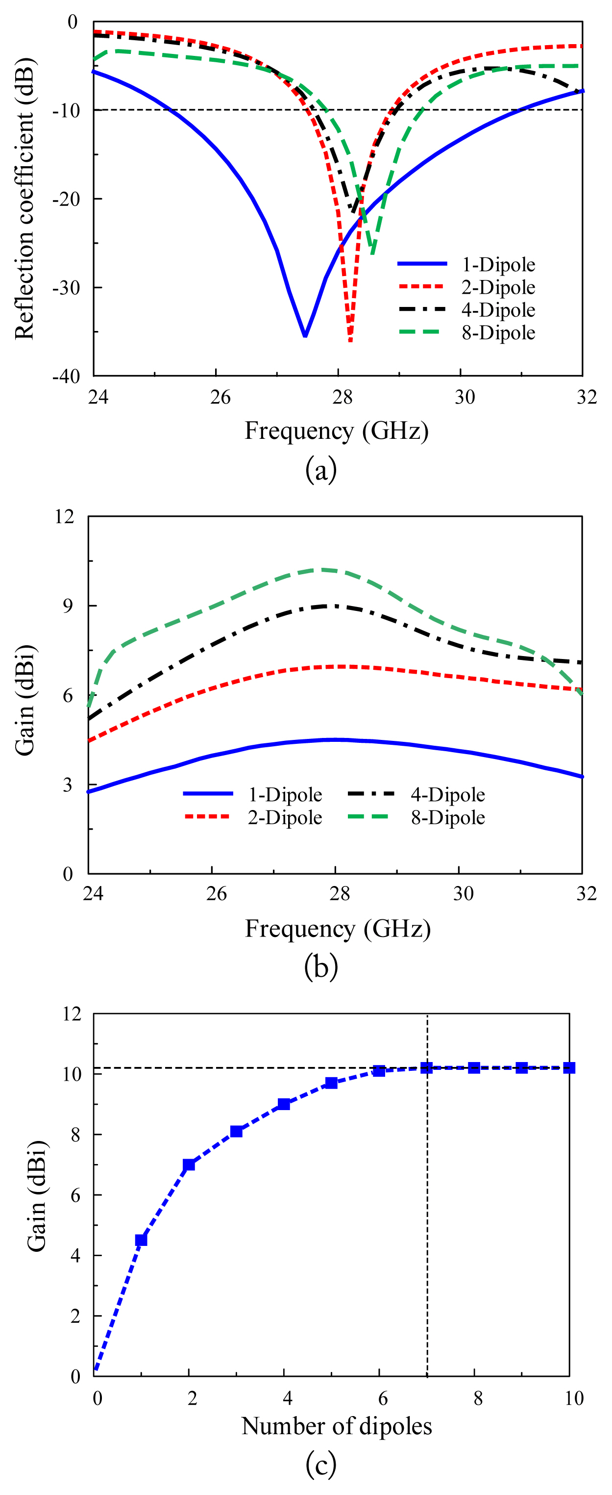
Simulation results of one-, two-, four-, and eight-dipole antennas at 28 GHz: (a) reflection coefficient, (b) gain, and (c) gain with respect to the number of dipoles.
When the number of dipole elements forming the series-fed endfire array antenna is large, the phase constant (β) of the feed-line connecting the dipole elements should be close to the wave number of free space to obtain high gain [26]. Because the phase constant of the parallel strip line in this study is larger than the wave number of free space (ko), the gain increment cannot be achieved when more than a certain number of dipole elements are used.
Fig. 5 shows the surface current distribution of an array antenna consisting of two-, four-, eight-, and twelve-dipole elements. Although the number of dipoles increases on the array antenna, the current is not concentrated on a specific dipole and is uniformly distributed. Fig. 6 shows the surface current vectors of the antennas with one-, two-, three-, and four-dipole elements. For the array antennas composed of one-, two-, and three-dipole elements, the phase difference of the current between the adjacent dipole elements is close to 180°. As a result, constructive interference occurs, which increases the gain of the array antenna in the endfire direction. However, the array antenna with four dipoles does not significantly increase the gain because the phase difference of the currents of the third and fourth dipoles is close to being in-phase. As the number of dipoles increases, the phase difference between the adjacent dipole elements becomes in-phase more frequently. Therefore, the gain does not increase when more than a certain number of dipole elements are used.
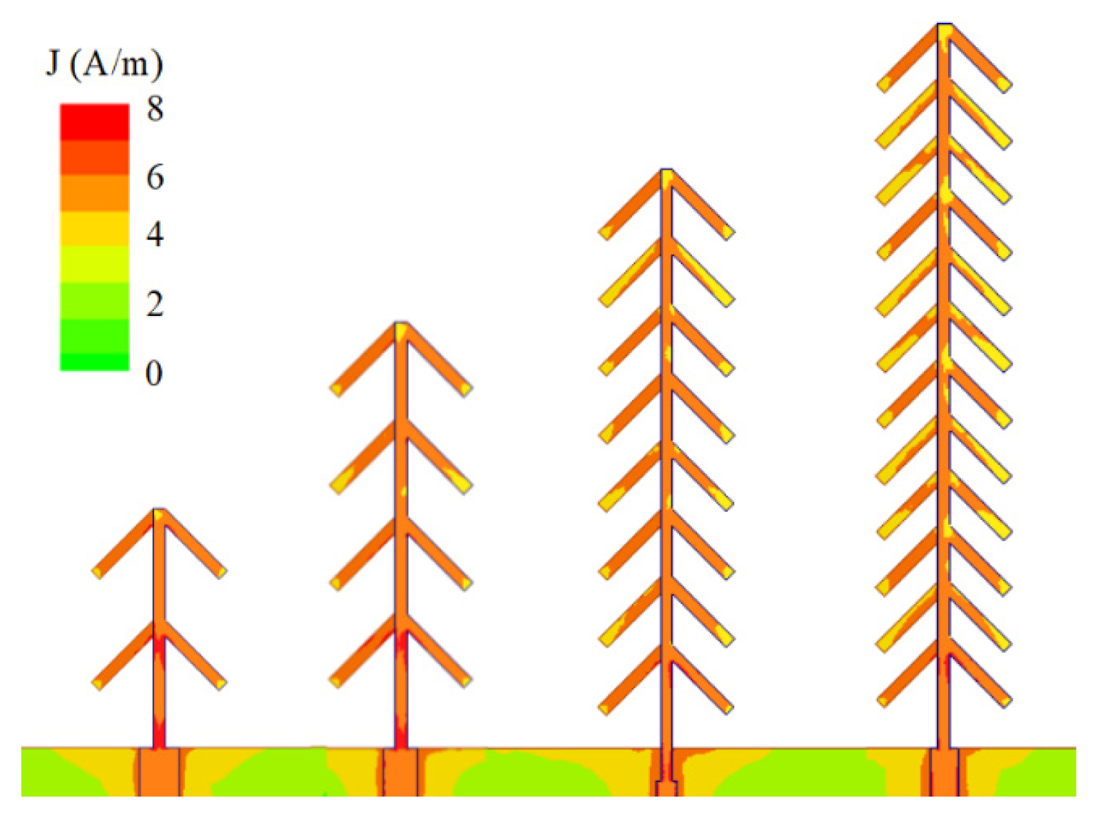
Current distribution of the printed two-, four-, eight-, and twelve-element dipole array antennas.
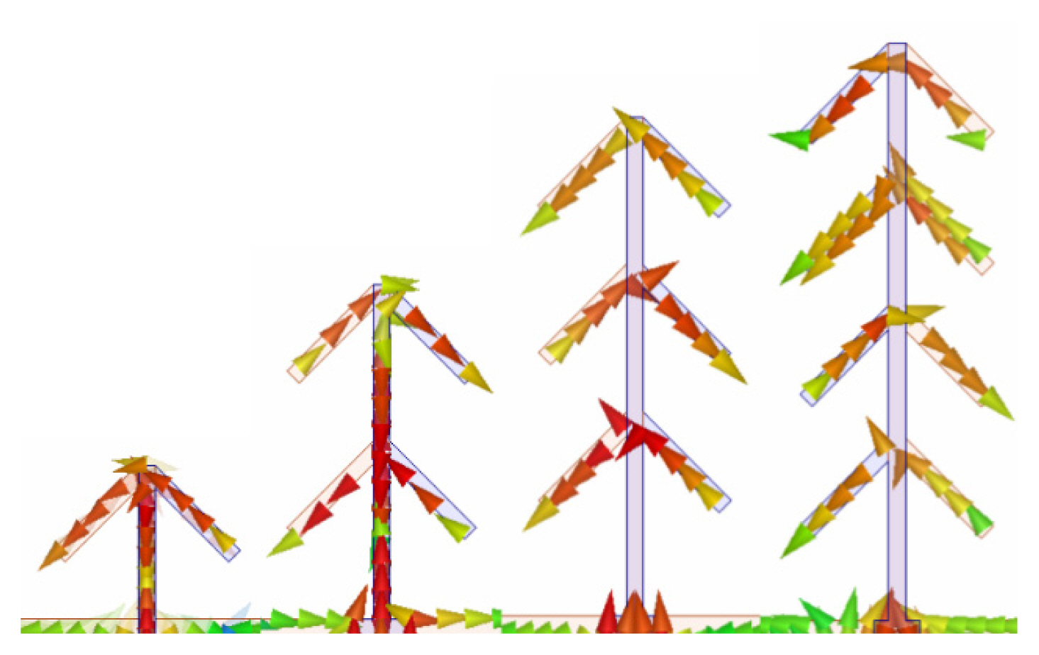
Current vector of the printed one-, two, three-, and four-element dipole array antennas.
Fig. 7 shows the normalized radiation pattern at the center frequency of 28 GHz. As the number of dipoles increases, the HPBWs of the xz- and yz-planes of the radiation patterns became similar. As the number of dipoles increases, the directivity increases, and the influence of the reflected power in the truncated ground plane is reduced. Therefore, the radiation pattern of the xz- and yz-planes presented more symmetrically. For four or more dipoles connected in a series, the HPBW difference between the xz- and yz-planes was significantly reduced to less than 20°. The HPBW differences between the xz- and yz-planes of the designed one-, two-, four-, and eight-dipole arrays were 156.7°, 28.8°, 14.1°, and 5.3°, respectively. In the xz-plane radiation pattern, the difference between HPBWR and HPBWL was less than 2°, and more symmetrical radiation patterns were obtained. The differences between HPBWL and HPBWR for the xz-plane of one-, two-, four-, and eight-dipole arrays were 5.4°, 2.4°, 1.6°, and 0.8°, respectively. For multiple dipoles connected in a series, the cross-polarization components in each dipole cancelled each other out. Therefore, the cross-polarization level was lower than in a single dipole antenna. The characteristics of the one-, two-, four-, and eight-dipole arrays are shown in Table 2.
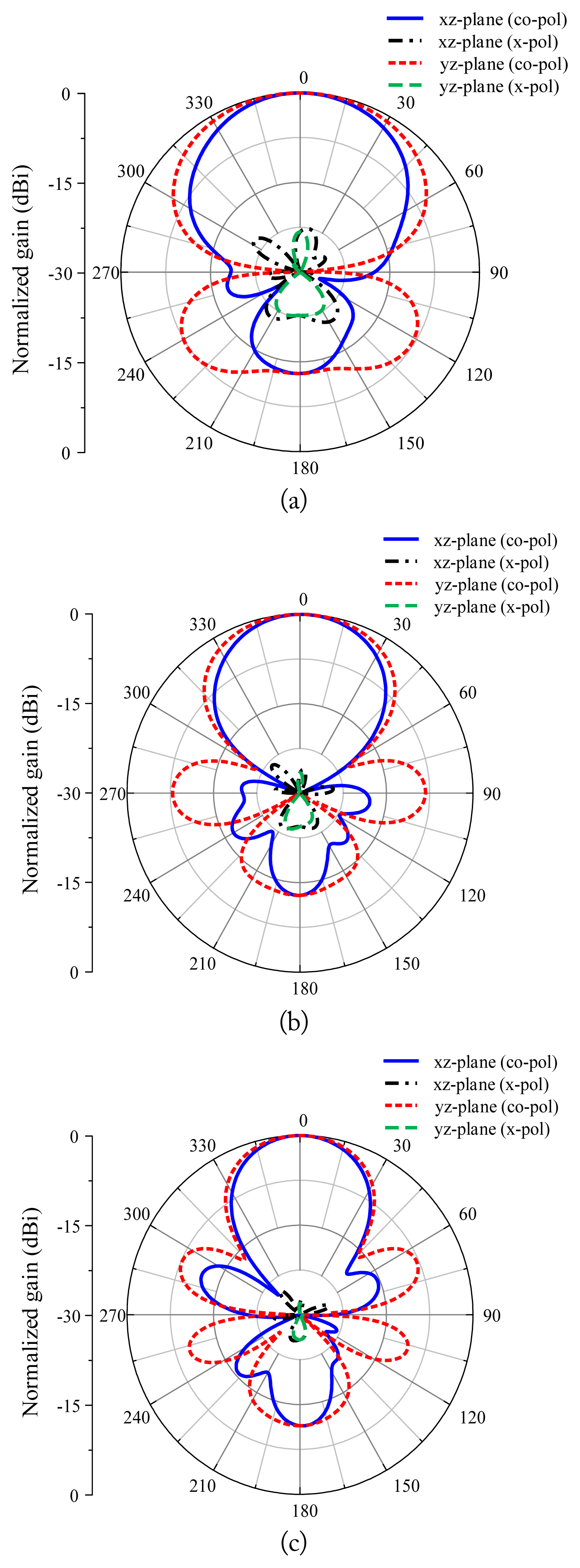
Normalized radiation pattern of the dipole array antennas at 28 GHz: (a) two-dipole, (b) four-dipole, and (c) eight-dipole.
Radiation pattern characteristics
IV. Measurement Results
The printed angled dipole array antenna with four-dipole elements connected in a series was fabricated, and the reflection coefficient, gain, and radiation pattern were measured. Fig. 8 is a photograph of the fabricated antenna. The Rohde & Schwarz ZVA 67 VNA was used to measure the reflection coefficient, and MTG Corp.’s anechoic chamber was used to measure the radiation pattern. Fig. 9 shows the simulated and measured results of the fabricated antenna. The measured −10 dB impedance bandwidth of the four-dipole array antenna is 27.2–29.0 GHz. The measured impedance bandwidth is nearly the same as the simulated result of 27.6–28.9 GHz. The measured gain at the center frequency of 28 GHz is 9.0 dBi, and the HPBWs in the xz- and yz-planes are 54.6° and 68.7°, respectively. The 3-dB gain bandwidth of the array antenna is 23.6–33.5 GHz.
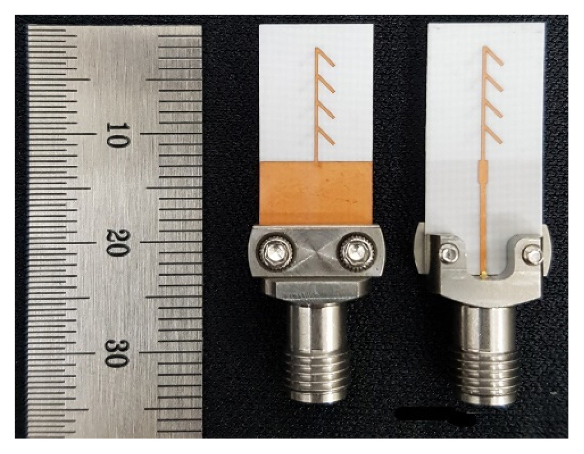
Photograph of the printed four-element dipole array antenna.
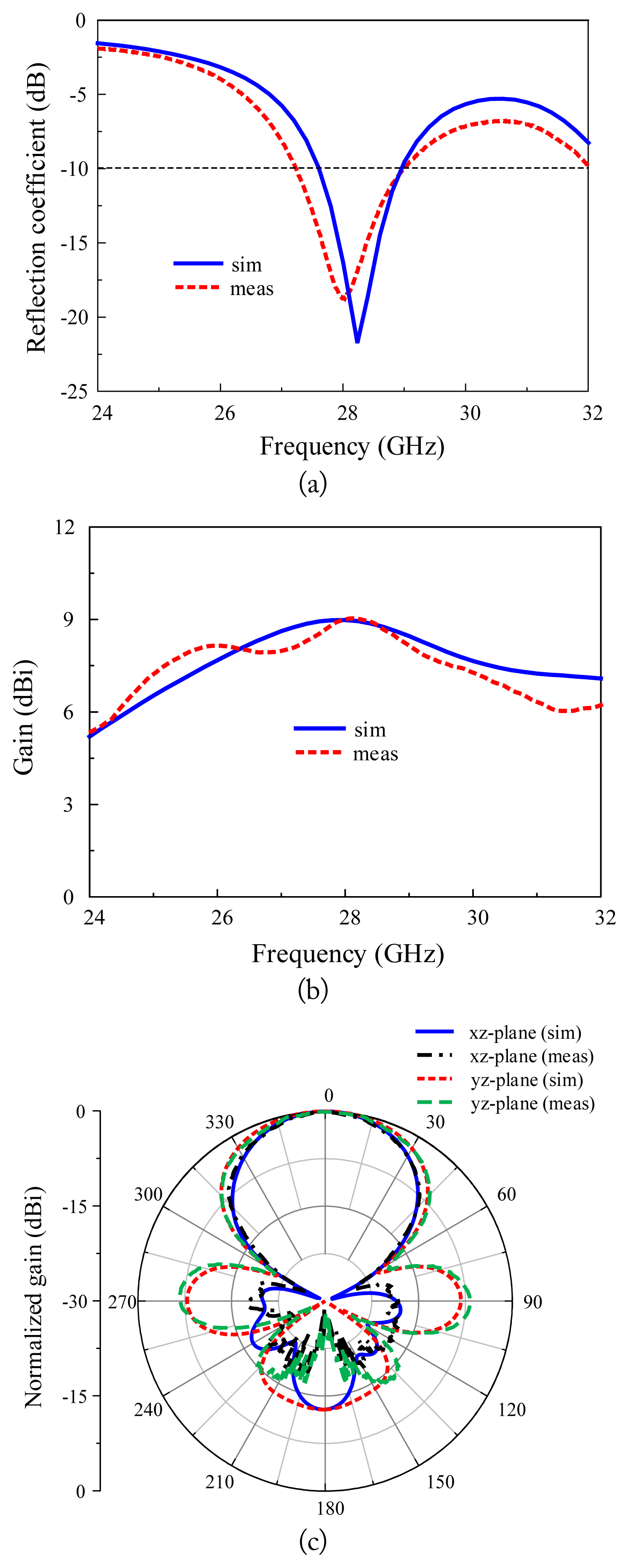
Comparison between the measured and simulated results: (a) reflection coefficient, (b) gain, and (c) radiation pattern at 28 GHz.
The measured gain at 28 GHz is almost the same as the simulated results, and the HPBWs in the xz- and yz-planes are 56.1° and 68.5°, respectively. The measured 3-dB gain band-width is 24.3–32.2 GHz, which is approximately 1.0 GHz narrower than the simulated results.
V. Conclusion
This paper demonstrated that when using multiple angled dipoles, series-fed array antennas can achieve higher gains, more symmetrical radiation patterns, and lower cross-polarization levels than single angled dipole antennas. We designed two-, four-, and eight-dipoles in a series, and the gains at the center frequency of the array antennas were 7.0 dBi, 9.0 dBi, and 10.2 dBi, respectively. The single angled printed dipole exhibited a large HPBW difference of 156.7° between the xz- and yz-planes, and the radiation pattern of the xz-plane was asymmetrical. By connecting four or more dipoles in a series, the HPBW difference between the xz- and yz-planes was greatly reduced. In addition, the radiation pattern of the xz-plane presented symmetrically. Therefore, the proposed structure presented a high gain and symmetrical radiation pattern. It was also lighter and cheaper than antenna structures using metal cavities and significantly easier to optimize than quasi-Yagi antennas using several directors. Therefore, the proposed antenna could prove useful for 5G communication systems.
Acknowledgments
This work was supported in part by the National Research Foundation (NRF) of Korea grant funded by the Korean government (MSIT) (No. 2018R1D1A1A02086071); in part by the “Human Resources Program in Energy Technology” of the Korea Institute of Energy Technology Evaluation and Planning (KETEP)-granted financial resources from the Ministry of Trade Industry & Energy, Republic of Korea (No. 20184030292220); and in part by the GRRC program of Gyeonggi province (No. GRRC-AJOU-2016B01, Photonics-Medical Convergence Technology Research Center).
References
Biography

Heesu Wang
received his B.S. and M.S. degrees in Electrical and Computer Engineering from Ajou University, Suwon, Korea, in 2018 and 2020, respectively. He is currently studying for his Ph.D. at the Department of Electrical and Computer Engineering at Ajou University, Suwon, Korea. His research interests include the design of patch antennas, printed antennas, small antennas, and metasurface antennas for various wireless communication applications.

Ikmo Park
received his B.S. degree in Electrical Engineering from the State University of New York at Stony Brook and his M.S. and Ph.D. degrees in Electrical Engineering from the University of Illinois at Urbana-Champaign. He joined the Department of Electrical and Computer Engineering at Ajou University, Suwon, Korea, in 1996. He has authored and coauthored over 300 technical journals and conference papers. He also holds over 40 domestic and international patents. He served as a Chair of the Department of Electrical and Computer Engineering at Ajou University, and he is a member of the Board of Directors at the Korea Institute of Electromagnetic Engineering and Science (KIEES). He serves as the Editor-in-Chief for the Journal of KIEES, an Editorial Board member for the International Journal of Antennas and Propagation, an Editorial Board member for MDPI’s Electronics, and an Associate Editor for the IET’s Electronics Letters. He has also served as an Editorial Board member of the Journal of Electromagnetic Engineering and Science. He currently serves as chair, organizer, and member of program committees for various conferences, workshops, and short courses in electromagnetic-related topics. His present research interests include the design and analysis of microwave, millimeter-wave, terahertz wave, and nano-structured antennas with metamaterials and metasurfaces.