I. Introduction
High-power microwave (HPM) systems have been actively studied. To design an HPM system, a high-gain antenna and HPM source are essential for high effective radiated power (ERP). Conventionally, reflectors, horns, and helical antennas [1ŌĆō4] have been studied for use in HPM systems. These antennas have robust structures to withstand very high power. Among them, the reflector antenna, which has high-gain characteristics, has a very large size. It has back lobe radiation due to spillover. Owing to the low front-to-back ratio (FBR) from spillover, the high back lobe causes a malfunction of the near system and radiation hazards for the person operating the device. For these high-gain antennas, one very high-power source is used. However, designing a high-power source is difficult and expensive [5]. In other words, arrayed medium-power sources and arrayed antennas are suitable for designing high-power sources, and arrayed antennas are appropriate for designing high-ERP microwave systems in terms of cost and design of the power source. Therefore, one large source generator is needed to substitute for several medium-power sources to generate a high ERP. A reflector antenna is also needed to reduce the back lobe in the HPM antenna design.
In this paper, we report a 2 ├Ś 2 array synthesis horn antenna for an HPM system with an arrayed medium-level power source. A pyramidal horn antenna is designed at 2.45 GHz as an array antenna element. Then, the horn antenna is arrayed in a 2 ├Ś 2 configuration to apply an arrayed power source with an extended horn to obtain a high gain. To convert the mode from TE20 to TE10, the vertical junction of the array antenna is controlled. The two-stepped and partitioned corrugate structures are attached to both apertures of the antenna to improve the FBR. The simulated and measured results are described in the next section.
II. Antenna Design
Genetic algorithms are widely used as an optimization design technique for antennas [6]. They are used for effective optimization while satisfying multiple design goals. Specific design variables are assigned to obtain the characteristics of the target horn antenna.
Conversely, in this paper, the optimization design is carried out with CST Microwave Studio 2010 using the sequential design optimization method. This study begins with the design of a basic horn antenna based on theory, and the antenna parameters are individually optimized for the design. The final characteristics are derived by sequential optimization without using any algorithm.
A pyramidal horn antenna, shown in Fig. 1(a), is designed at 2.45 GHz through a simulation. A coaxial probe feed structure and a WR-340 waveguide are used for the feed. This feed structure can be changed according to the structure of the power sources. Here, we simply use the coaxial probe feed to easily verify the antenna performance. The input impedances are well matched below the return loss of 10 dB, and the 10 dB return loss bandwidth is measured within 74 MHz (1.94ŌĆō2.68 GHz) for all ports. A gain of 10.2 dBi is obtained in the simulation. The half-power beamwidths (HPBWs) of the E-plane and H-plane are 50.4┬░ and 59.8┬░, respectively. The size of the pyramidal horn antenna is 122.5 mm ├Ś 122.5 mm ├Ś 364 mm (1╬╗ ├Ś 1╬╗ ├Ś 2.97╬╗), where ╬╗ is the wavelength in free space at 2.45 GHz.
Then, the designed pyramidal horn antennas are arrayed in a 2 ├Ś 2 configuration to synthesize the beam for high gain, as depicted in Fig. 1(b). The array distance is set to 1╬╗ to achieve a narrow beamwidth. The gain of the array antenna is increased to 16.4 dBi, and the HPBWs are narrowed to 25.3┬░ in the E-plane and 25.4┬░ in the H-plane. To obtain a high gain, we attach an extended horn with dimensions of 500 mm ├Ś 500 mm ├Ś 637.5 mm (4.08╬╗ ├Ś 4.08╬╗ ├Ś 5.21╬╗) in front of the 2 ├Ś 2 array horn antenna, as shown in Fig. 1(c).
As a result of the simulation, the TE20 mode occurs because of the extended horn in the 2 ├Ś 2 array horn antenna with an extended horn. The TE20 mode causes a beam ripple in the HPBW, a large HPBW of 42.6┬░ in the H-plane, and an HPBW of 14.0┬░ in the E-plane because of the vertical junction and boundary of the extended horn. To improve the radiation pattern in the H-plane, the mode at the junction between the 2 ├Ś 2 array horn antenna and the extended horn should be changed from TE20 to TE10. Therefore, a parameter study for the vertical junction length (VJL) is performed through a simulation.
Figs. 2 and 3 show the simulated H-plane patterns and E-field distributions in the observation plane, not in the waveguide, by varying the VJL parameter. The TE20 mode can be verified from the E-field distribution at a VJL of 200 mm, as shown in Fig. 3. The length of the extended horn is fixed at 635.7 mm (5.21╬╗).
The VJL is changed from 200 mm to 0 mm in four steps, and the H-plane pattern is observed. As shown in Fig. 2, the HPBW and the side-lobe level decrease when the VJL is reduced, and the gain increases. To obtain a good H-plane pattern, we chose the VLJ of 60 mm. As depicted in Fig. 3(b), the conversion from the TE20 to the TE10 mode can be conducted when the VJL is 60 mm.
When the TE20 mode is generated, the gain is 18.2 dBi and the HPBWs of the E-plane and the H-plane are 14.0┬░ and 42.6┬░, respectively. Conversely, the gain is 21.3 dBi in the case of the antenna with the TE10 mode. The HPBWs in the E-plane and the H-plane are 14.1┬░ and 14.0┬░, respectively. Thus, the HPBW is decreased by 28.6┬░ in the H-plane, and the gain is improved by 3.1 dB because of the conversion of the TE20 mode to TE10.
At the same time, suppressing the back lobe is required for high-power antennas because these antennas radiate tremendous power and can have a considerable effect on human bodies nearby, even when the back radiation level is low. Consequently, to significantly reduce the back radiation level, corrugated structures [7] with a depth of 90 mm (0.735╬╗) and a width of 166.6 mm (1.36╬╗) are added to the top and bottom of the ends of the synthesis horn. Two-stepped corrugated structures are installed to optimize the reduction of the back radiation level. The diffraction on the aperture of the horn antenna is large in the E-plane, and the H-plane removes the field through the boundary condition. The second step is to offset the backward direction by 35 mm (0.286╬╗) and divide it into three sections, so that it is shaped like a waveguide. Therefore, a ┬Š ╬╗ short stub function is generated in this space, effectively reducing the back radiation level.
III. Simulated and Measured Results
A 2 ├Ś 2 array synthesis horn antenna with an extended horn is fabricated to compare its radiation properties according to whether it has two-stepped and partitioned corrugated structures, as shown in Figs. 1(c) and 4. The antenna is made using a copper sheet, and a 10 mm-thick styrofoam is used as the supporting material. A coaxial probe with an N-type connector is used for the feed. A four-way T-junction power divider is connected to the N-type connector to measure the radiation pattern. The insertion loss, including the coaxial cables and the substrate of the power divider, is 1.15 dB. The input impedance of each port matches well with the return loss of below ŌłÆ10 dB, as shown in Fig. 5.
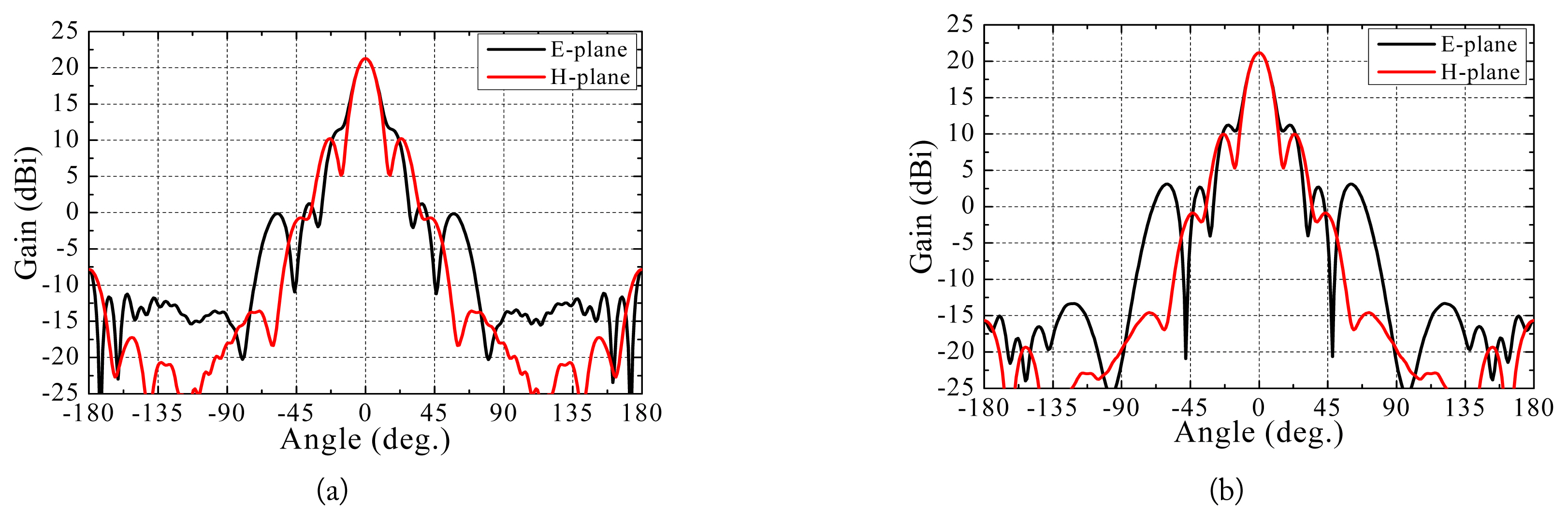
The simulated and measured radiation patterns of the proposed antenna according to the presence or absence of two-stepped and partitioned corrugated structures are shown in Figs. 6 and 7. When the corrugated structure is present, the HPBWs do not change in either the simulation or the measurement. The gains of the array synthesis horn antenna with the corrugated structure are 21.2 dBi in the simulation and 19.7 dBi in the measurement. The discrepancy between the simulation and the measurement is a result of the loss of the four-way T-junction power divider.
Therefore, we can confirm that the corrugated structure has no effect on the main beam. Conversely, the average level of the back radiation from 90┬░ to 180┬░ and from ŌłÆ90┬░ to ŌłÆ180┬░ decreases in the E-plane, and the FBR increases by 7.7 dB in the simulation and 6.4 dB in the measurement. This outcome is a result of the short stub effect of the corrugated structures and the suppressed creeping currents on the external surface of the antenna synthesis horns. The characteristics of the designed antennas are summarized in Table 1.
IV. Conclusion
In this study, we designed and fabricated a 2 ├Ś 2 array synthesis horn antenna for HPM applications. To obtain a high gain, the pyramidal horn antenna was arrayed in a 2 ├Ś 2 configuration, and an extended horn was added to the front of the array horn antenna. Mode conversion was performed by controlling the vertical junction length for a good radiation pattern in the H-plane. To reduce the back lobe, two-stepped corrugated structures were attached to the aperture of the horn antenna. The designed antenna had a gain of 19.7 dBi and a front-and-back ratio of 39.6 dB. The results suggest that the designed antenna is appropriate for HPM applications.