 |
 |
- Search
| J. Electromagn. Eng. Sci > Volume 20(1); 2020 > Article |
|
Abstract
This paper presents a method for solving receiver misalignment (axial or angular) problems in wireless power transfer systems using a multiple-input single-output system. The optimum magnitudes and phases of the transmitter voltages and receiver load for maximum efficiency are derived in convenient analytical forms when negligible mutual couplings between transmitters. These solutions are validated by genetic algorithm optimization and electromagnetic-simulation results for a design ex-ample of two transmitters and one rotating receiver.
Wireless power transfer (WPT) using resonance through magnetic couplings has been actively studied since it was proposed by Soljacic in 2007 [1]. Efficiency analysis of a one-transmitter (Tx) and one-receiver (Rx) system facing each other has been sufficiently performed, and related products can be found in the market. However, the degree of freedom of the receiver positions and postures is still limited. Some studies have been conducted to solve the misalignment problems occurring between Tx and Rx. The misalignment can be divided into two types: axial and angular. A theoretical research on multiple-input single-output (MISO) systems was conducted in [2]. In [3], an energy-efficient and adaptive design method for wireless power transfer in electric vehicles was proposed to alleviate the axial misalignment problem using multiple transmitters. To maximize the power transfer efficiency, the Tx phases and Rx loads were simultaneously optimized based on the same Tx magnitudes. In [4], the solution for the Tx voltages was presented assuming a fixed Rx load. In [5], a plurality of repeaters was attached to the Tx and Rx to solve the misalignment problem. In [6], the three Tx sources with phase differences were used to stably transfer power to an Rx. Through the phase control of orthogonally arranged TxŌĆÖs, the direction of the magnetic field was controlled to solve the angular problem [7, 8]. The solutions for the excitation voltage magnitudes and phases for a two-Tx MISO system were numerically found to maximize the efficiency [9].
In this paper, we propose a more general MISO WPT system, the excitation magnitudes and phases and the Rx load of which are simultaneously optimized to achieve maximum efficiencies despite these misalignments. Besides, we obtain the closed-form solution of the excitation voltages for the case of negligible mutual couplings between the TxŌĆÖs. In Section II, we briefly summarize the formulas for single-input single-output (SISO) systems and describe the typical two situations in which the power transfer efficiencies become zero. In Section III, based on the derived analytic solution of a two-Tx example, we deduce the solutions of multiple Tx excitation magnitudes and phases for maximum efficiency in a general MISO system. They are validated with the results based on a generic algorithm (GA) and electromagnetic (EM) simulations. The paper is concluded in Section IV.
A SISO system is briefly reviewed to develop formulations for MISO systems. Fig. 1 shows the SISO systems in which axial and angular misalignments occur. In Fig. 1, k is the coupling coefficient [10, 11]. A positive k means the same magnetic flux direction crossing the Tx and Rx loops. A negative k means that the magnetic flux originating from the Tx loop flows into the Rx loop in an opposite direction. A circle is located above the Tx loop where k is zero or very small. Based on the equivalent circuit analysis in [11], efficiency (╬Ę) can be expressed as
In (1), Pin is the total input power, PL is the power supplied to the load with RL, and b is the normalized load resistance defined by b = RL/RL, opt, where
R L , o p t = R 0 1 + F 2 F = k Q 1 Q 2
Fig. 2 shows a general MISO system with one Rx loop. The Rx loop is randomly oriented with a tilted angle ╬Ė as shown. For the MISO WPT system in Fig. 2, a circuit equation can be written as
where the principal diagonal elements of the Z matrix at the resonant design frequency are
and
In (3) and (4), RiŌĆÖs are the loss resistances of the loops, and RL is the load resistance of the receiver. The remaining elements of [Z], mutual impedances, are given by
where kij is the coupling coefficient, Li is the self-inductance of the loops (or coils), and Mij is the mutual inductance. The column matrix [I] can be obtained by [Z]ŌłÆ1[V]. The total input power and the received power at the load resistance are
and
To maximize the efficiency (8), we have to optimize the Tx voltage (V1, V2, ŌĆ”, VN) magnitudes and phases and RL. Finding their analytical solutions considering all the system details given in (2) is usually difficult. Thus, some GA techniques, which are not easily available in industries, must be used to maximize the system efficiency in practice. However, in the case of small mutual impedances or inductances between TxŌĆÖs, some convenient solutions for a maximum efficiency can be found.
We start with a simple two-Tx system (N = 2) under the assumption of a negligible coupling between them. For this system, the current flowing on the Rx loop can be analytically obtained as
where
F i = k i 0 Q i Q 0
and
where
M i ( = k i 0 L i L 0 )
and
where Žå is the difference in the excitation phase (Žå1 ŌĆō Žå2). The total input power and received power are given by
and
respectively. Now, efficiency is expressed as
Defining m = |V2/V1|, efficiency (16) is clearly a function of three variables (m, Žå, and ╬▓) given by
The maximum of (17) occurs in which
and
are simultaneously satisfied. After some algebraic arrangements, the solutions are obtained as
and
As indicated, m is a real number. Maximum efficiency is mostly not obtained with the use of V1 = V2, which is usually applied in practice. When inserting these solutions into (17), the maximum efficiency is expressed as
where
After further algebraic simplification, (24) results in
where
F ( = F 1 2 + F 2 2 ) F = Ōłæ n = 1 N F n 2
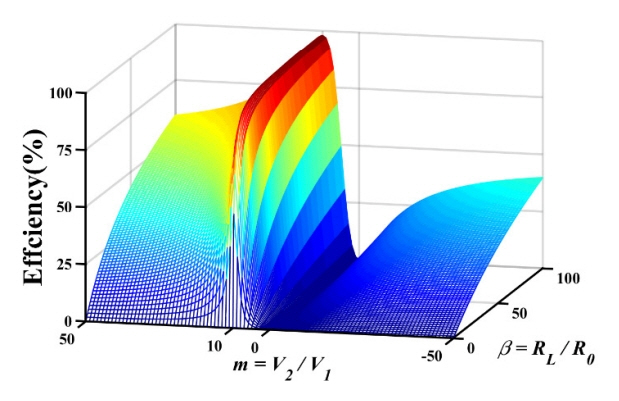
In Fig. 3, we plot the efficiency (17) as a function of m and ╬▓ for the case of F1 = 10, F2 = 100, and R0 = R1 = R2 = 0.01 ╬®. Fig. 3 shows that m and ╬▓ must have specific values to achieve maximum efficiency. When the voltage ratio m = V2/V1 = 10 and the normalized load impedance
╬▓ = 1 + F 1 2 + F 2 2 = 100.1
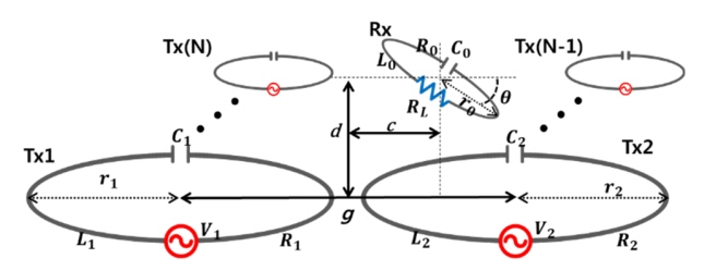
To validate the theory in Section II, circuit and EM simulations are performed for the case of r1 = r2 = 6 cm, r0 = 5 cm, d = 10 cm, c = 0 cm, and g = 20 cm in Fig. 4. The Tx and Rx loops are made of copper rings with a radius of 1 mm. In this case, R1 = R2 = 0.0408 ╬®, R0 = 0.034 ╬®, L1 = L2 = 0.335 ╬╝H, and L0 = 0.266 ╬╝H. We choose C1 = C2 = 1.65 nF and C0 = 2.07 nF for resonance at 6.78 MHz. The quality factors Q1 (or Q2) and Q0 are 348.6 and 334.2, respectively. The coupling coefficient (k21) [11] between the two TxŌĆÖs is ŌłÆ0.0064. The minus sign implies that the magnetic flux generated from one Tx loop crosses the other in an opposite direction. Thus, the figure of merit F12 = ŌłÆ2.23. The GA in MATLAB (optimization toolbox) is applied to find the optimum magnitude and phase of V2/V1 and the Rx load resistance (RL) through which the efficiency reaches a maximum. EM simulation was performed by ANSYS HFSS using copper loops and lumped C components for resonance. From the EM simulation, we obtain the scattering matrix and coupling coefficients between all copper loops.
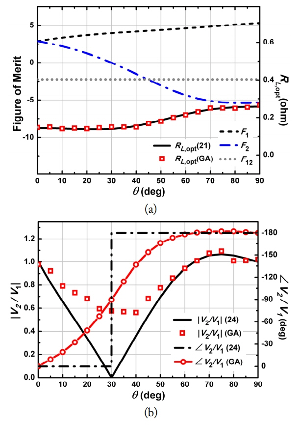
Fig. 5(a) presents the figures of merit (F1, F2) and optimum load resistances using the GA and Eq. (21) as a function of the misalignment angle ╬Ė at 0┬░ŌĆō90┬░. While
F 1 ( = k 10 Q 1 Q 0 ) F 2 ( = k 20 Q 2 Q 0 )
Fig. 5(b) shows the optimized magnitude and phase of the voltage ratio (m = V2/V1) as a function of the misalignment angle ╬Ė using the GA and (24). The magnitudes and phases of V2/V1 using the GA and (24) are in agreement except at around ╬Ė = 30┬░. The discrepancies around ╬Ė = 30┬░ comes from the fact that, while the assumption made for (24) is the smaller mutual coupling (|F1| > |F12|) and |F2| > |F12|), |F2| is much smaller than |F12| at around ╬Ė = 30┬░.
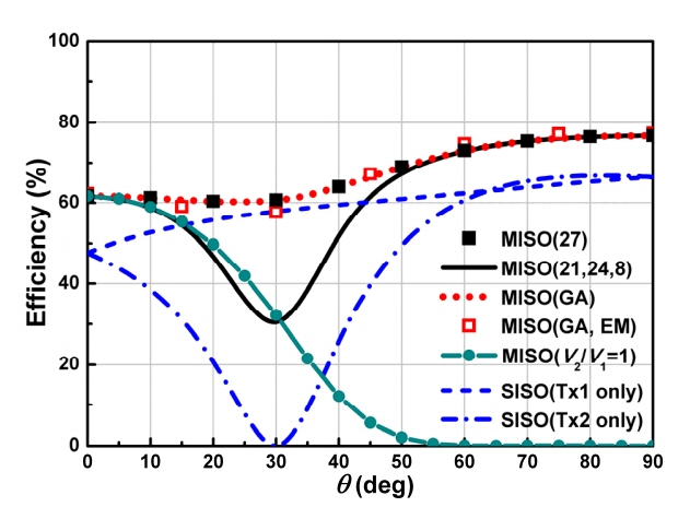
In Fig. 6, the efficiencies based on the GA, Eqs. (21, 24, 8), Eq. (27), and EM-simulation are plotted as a function of the misalignment angle for the same system. The efficiencies for the SISO systems using only Tx1 or Tx2 are also included for comparison. The MISO (21, 24, 8) is calculated by inserting Eqs. (21, 24) into (8). The MISO (27) and MISO (GA) are shown to be in excellent agreement. The EM-simulated efficiency MISO (EM) using |V2/V1| (GA) and ŌłĀV2/V1 (GA) in Fig. 5(b) also agrees with them. These efficiencies are shown to be higher than those of the SISO systems. The MISO (21, 24, 8) is also shown to be higher than the SISO in which |F12| (= 2.23) is roughly smaller than the system figure of merit F. As |F12| > F, near ╬Ė = 30┬░, we need to optimize the system parameters considering the mutual couplings. However, the evaluation of the maximum MISO efficiency is shown to have been exactly conducted with (27) not depending on the information of mutual coupling. The common practice of using the same Tx voltages (V2 = V1) is against the solution (22) and leads to much lower efficiencies than the achievable maximum as shown by MISO (V2/V1 = 1) in Fig. 6.
The misalignment problems have been shown to be always solved by MISO through the numerical optimization of Tx excitations (magnitudes and phases). They have been analytically obtained and provided in this study when the mutual inductances are relatively small. Further research is needed to fabricate the proposed MISO system and validate the theory with experimental results.
Acknowledgments
This research was supported by the MSIT (Ministry of Science and ICT), Korea, under the Information Technology Research Center support program (No. IITP-2019-2016-0-00291) supervised by the Institute for Information & Communications Technology Promotion (IITP).
Fig.┬Ā4
MISO (N = 2) WPT system with an angular misalignment angle ╬Ė (g = distance between the center of two TxŌĆÖs, d = vertical distance between the origin and Rx0): (a) overall view and (b) front view.

Fig.┬Ā5
MISO (N = 2) system parameters, optimized loads, and input voltage ratio (V2/V1) as a function of the misalignment angle ╬Ė for the case of r1 = r2 = 6 cm, r0 = 5 cm, d = 10 cm, c = 0 cm, and g = 20 cm in Fig. 4: (a) figures of merit (F1 and F2) and optimum load, and (b) magnitude and phase of m (= V2/V1).

References
1. A Kurs, A Karalis, R Moffatt, JD Joannopoulos, P Fisher, and M Soljacic, "Wireless power transfer via strongly coupled magnetic resonance," Science, vol. 317, no. 5834, pp. 83ŌĆō86, 2007.


2. D Ahn and S Hong, "Effect of coupling between multiple transmitters or multiple receivers on wireless power transfer," IEEE Transactions on Industrial Electronics, vol. 60, no. 7, pp. 2602ŌĆō2613, 2013.

3. X Mou, O Groling, and H Sun, "Energy-efficient and adaptive design for wireless power transfer in electric vehicles," IEEE Transactions on Industrial Electronics, vol. 64, no. 9, pp. 7250ŌĆō7260, 2017.

4. H Hu, S Yao, K Bao, and SV Georgakopoulos, "Misalignment insensitive WPT with conformal SCMR systems," In: Proceedings of 2015 IEEE International Symposium on Antennas and Propagation & USNC/URSI National Radio Science Meeting; Vancouver, Canada. 2015;pp 117ŌĆō118.

5. JPK Sampath, A Alphones, and DM Vilathgamuwa, "Figure of merit for the optimization of wireless power transfer system against misalignment tolerance," IEEE Transactions on Power Electronics, vol. 32, no. 6, pp. 4359ŌĆō4369, 2016.

6. S Goguri, R Mudumbai, and A Kruger, "Optimizing wireless power transfer with multiple transmitters," In: Proceedings of 2017 51st Annual Conference on Information Sciences and Systems (CISS); Baltimore, MD. 2017;pp 1ŌĆō5.

7. Q Zhu, M Su, Y Sun, W Tang, and AP Hu, "Field orientation based on current amplitude and phase angle control for wireless power transfer," IEEE Transactions on Industrial Electronics, vol. 65, no. 6, pp. 4758ŌĆō4770, 2018.

8. T Mei, F Liu, C Jiang, X Chen, and RM Kennel, "Magnetic-field-model based analysis of two-phase magnetically coupled resonant wireless power transfer system," In: Proceedings of 2018 IEEE Applied Power Electronics Conference and Exposition (APEC); San Antonio, TX. 2018;pp 1092ŌĆō1097.

9. P Kong and H Ku, "Efficiency optimising scheme for wireless power transfer system with two transmitters," Electronics Letters, vol. 52, no. 4, pp. 310ŌĆō312, 2016.

Biography

Hyeongwook Lee received the B.S. in electronic engineering from Kyung Hee University, Yongin, Korea, in 2019. He is currently working toward the M.S. degree in electronic engineering in Kyung Hee University. His research interests are microwave antenna, passive devices, and wireless power transmission.
Biography

Seunghyun Boo received his B.S. and M.S degrees in electronics engineering from Kyung Hee University, Yongin, Korea, in 2017 and 2019, respectively. His research fields include microwave antennas, passive devices, and wireless power transmission.
Biography

Gunyoung Kim received a B.S. in Radio Communication Engineering from Kyung Hee University, Yongin, Korea in 2010, an M.S. in Electronics and Radio Engineering from Kyung Hee University in 2012, and a Ph.D. in Electronics Engineering from Kyung Hee University in 2018. Currently, he is a post-doctor in the College of Electronics and Information at Kyung Hee University. His fields of research include microwave antennas, passive devices, wireless power transmission, and metamaterials.
Biography

Bomson Lee received the B.S. degree in Electrical Engineering from Seoul National University, Seoul, Korea, in 1982. From 1982 to 1988, he was with the Hyundai Engineering Company Ltd., Seoul, Korea. He received the M.S. and Ph.D. degrees in Electrical Engineering from the University of Nebraska, Lincoln, NE, USA, in 1991 and 1995, respectively. In 1995, he joined the faculty at Kyung Hee University, where he is currently a professor in the Department of Electronics and Radio Engineering. From 2007 to 2008, he was the chair of the technical group for microwave and radio wave propagation in the Korea Institute of Electromagnetic Engineering & Science (KIEES). In 2010, he was an editor-in-chief of the Journal of the Korean Institute of Electromagnetic Engineering and Science. In 2018, he served as the president of KIEES. His research activities include microwave antennas, RF identification (RFID) tags, microwave passive devices, wireless power transfer, and metamaterials.
- TOOLS
- Related articles in JEES


