Wireless Power Transfer Efficiency Formula Applicable in Near and Far Fields
Article information
Abstract
Microwave-based wireless power transfer in the near field (up to about 10 m) is now drawing much interest since the transfer range when using current magnetic induction or magnetic resonance methods is limited in current industry. The Friis efficiency formula is valid only in the far field, so this paper proposes a new efficiency formula for use in the near field as well as in the far field. The proposed formula is derived under the assumption that the fields generated from transmitting-antenna elements are coherently (or constructively) added at a receiving antenna. The proposed formula is validated by EM-simulations and measurements using a 1 × 8 phased array antenna. The proposed efficiency formula is shown to be accurate in the near field and converge to the Friis formula in the far field.
I. Introduction
Conventionally, antennas have primarily been used to communication information across long distances. The transferred power was well formulated by Friis [1]. This well-known equation has long been used and is still a reliable formula as long as the distance between a transmitter (Tx) and a receiver (Rx) is very long, such that the electromagnetic waves generated from the Tx antenna reach the Rx as a nearly plane wave. The same antennas have also been studied for wireless power transfer [2]. However, this has rarely been used for commercial applications over far ranges due to low efficiencies. Recently, microwave beam-forming array antennas were introduced for near-field (up to about 10 m) wireless power transfer [3–5]. As long as the total power is properly regulated to circumvent human hazard issues, this approach has the potential to be widely applicable to wireless-power mobile devices, especially low-power Internet-of-Things (IoT) sensors for energy autonomy [6, 7]. In the far field, the antenna beam is usually scanned to a specific direction given by (θ, φ).
However, in the near field, it should be directed to a specific point given by (r, θ, φ). For far- and near-field transmissions, the feeding phases of the Tx array should be properly controlled such that the fields from the array elements are coherently added in the direction and at the position of the Rx, respectively, to achieve maximum efficiency. This coherent reception at the Rx position is also possible via the retrodirective method, in which a pilot RF signal from the Rx is necessary [8]. Power transfer efficiency formulas in the near field for the case of coherent feeding (or reception at the Rx position) are rarely found in the literature, although some corrections have been made to the Friis equation [1] in the near field for broadside arrays using in-phase feeding [9, 10].
In this paper, we propose a relatively simple efficiency formula that can be used in the near field as well as in the far field. The efficiencies based on the proposed formula are compared with those of EM-simulations and measurements.
II. Theory
The efficiency of the wireless link between Tx and a Rx was well formulated by Friis as follows [1]:
where Pt is the transmitted power at Tx, Pr is the received power at Rx, Gt is the Tx antenna gain, Gr is the Rx antenna gain, R is the distance between the Tx and Rx, and λ is the wavelength in free space. The efficiency (1) is estimated as a function of a direction, say η(θ, φ). For (1) to be accurate, the distance, R, should satisfy R ≥ 2D2 / λ, where D is the largest linear dimension of either of the antennas [1]. In the near field (R ≪ 2D2 / λ, there is an ambiguity regarding R, which is defined here as the distance between the center of the Tx array antenna and Rx as shown in Fig. 1. Thus, we need to derive an appropriate formula to address this situation under the assumption that the electric fields from the transmitting antenna elements are coherently added at a receiving antenna. This coherent feeding is possible by controlling the phases of the Tx array elements when the Rx position is known. Another approach is the retrodirective array [5], in which radiation elements reverse the phases of a pilot incoming wave from the Rx, and as a result, the fields at the Rx position are coherently added regardless of the Rx position. Fig. 1 shows a configuration of an Rx antenna in the near range of a Tx array antenna with its elements spaced at d = λ/2. The Tx antenna consists of N elements, which transfer power to the receiving antenna. For the delivery of maximum power, the electric field must be constructively (or coherently) added at the Rx position by properly controlling the Tx element phases. When the powers of the Tx radiation elements are P1, P2, …, and PN, respectively, and the distances between the Rx antenna and each Tx element are R1, R2, …, and RN, respectively, the electric field, Ei, generated from the ith Tx array element is obtained as follows:
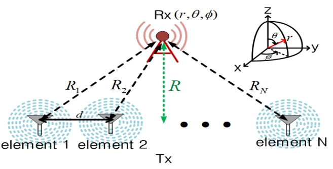
Configuration of the transmitting (Tx) and receiving (Rx) antennas in the near-field: R is assumed to be longer than λ/2 to avoid too much coupling.
This formula equates the power flux density,
where the direction, (θ, φ), may be different for each index, i, in general. The power flux density at the position of the Rx antenna is given by the following:
Then, the received power Pr is expressed as follows:
where Aer is the effective aperture area of the Rx antenna and Gr is the gain of the Rx antenna based on its directions, but here, we use the gain of the broadside for simplicity. The efficiency, η, is defined as the ratio of the received power, Pr, to the Tx input power, Pt, and is given by the following equation:
If the array element has an almost constant gain for all directions, the total gain of the Tx array antenna, Gt, may be approximated as Gt = NGt0. Furthermore, for a uniform array (Pi = P0 for i = 1, 2, …, N), (6) can be simplified to the following:
If we define the distance between the Rx antenna and the Tx array antenna as follows:
then (7) can be expressed with this equation:
Rmean is larger than the shortest of (R1, R2, ···, RN) and smaller than the arithmetic mean of (R1, R2, ···, RN). In the far field, since R1 ≈ R2 ≈ ··· ≈ RN = R and Rmean = R, (9) approaches the Friis transmission equation (1).
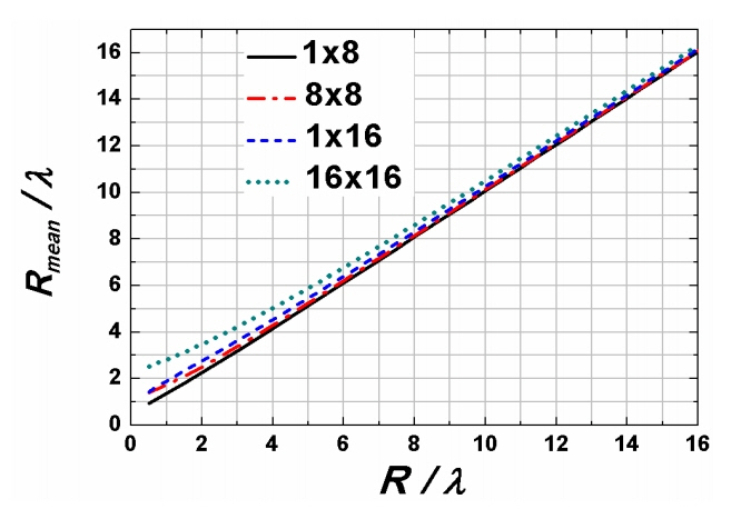
It may be useful if we evaluate (8) further. Fig. 2 shows (8) as R/ λ increases from 0.5 to 8 for 1 × 8, 8 × 8, 1 × 16, and 16 × 16 Tx array antennas. The spacing between the array elements is assumed to be λ/2. A single Rx is assumed. In (8), all of the distances from each Tx element to the Rx antenna are considered. For the largest array of 16 elements, the far-field distance, (2D2 / λ) is 128λ. This means that when R > 128λ, Rmean is very close to R. It is noted that when R = 16λ, Rmean ≈ 16.32 λ (2% larger than R). This discrepancy is shown to become larger as R/λ decreases. When R/λ is 2 for the case of the 16 × 16 array, Rmean/λ is 3.5, which results in 1/3 the transfer efficiency in (9) since (3.5/2)2 ≈ 3. To validate the efficiency formula (9), we first examine the method of evaluating the efficiencies from the S-parameter through EM-simulations. Since the fields from the Tx array elements are controlled to be added in-phase at the receiver, the efficiency based on EM-simulations is given by the following:
where RA is the antenna resistance of the Tx and Rx antenna elements, which are assumed to be the same, and S0i is the S-parameter from the ith Tx element to the receiver terminal. Thus, (10) is simplified to
For the special case of V1 = V2 = ··· = VN, (11) becomes
III. Validation of Theory
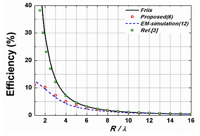
To validate the proposed efficiency formula (6), we compare it with (12) based on EM-simulations and the Friis formula (1) as well as ref. [3] in Fig. 3 as R/λ increases up to 16. The Tx array antenna consists of 8 × 8 half-wave dipole elements. The input impedance of each dipole element is 73 Ω, and their antenna gain is 1.69 at 2.4 GHz. The spacing between adjacent antennas is λ/2 (62.5 mm). For this case, 2D2 / λ = 32λ. While the efficiencies based on the Friis formula (1) show large discrepancies with those of EM-simulations, especially when R/λ is smaller than 4, the efficiencies based on the proposed formula (6) are in good agreement with the simulations in all ranges (R/λ ≧ 1). The proposed formula (6) is also shown to converge to (1) in the far field.
IV. Measurement
We have fabricated a circularly polarized Tx array antenna composed of 1 × 8 microstrip patch radiation elements operating at 2.4 GHz to examine its efficiencies in various practical environments. The gain of the Tx antenna is 14.7 dB (Gt = 29.7). The linearly polarized Rx antenna is also a patch type, and its gain is 6.9 dB (Gr = 4.8). Fig. 4 shows the entire system of a transmitting system. The schematic of a 1 × 8 Tx system and its fabricated photo are showed in Fig. 4(a) and (b). The system consists of a 2.4 GHz RF source, power dividers, attenuators, power amplifiers, patch radiation elements, and MCU. The magnitudes and phases for a coherent reception at Rx positions are controlled by an MCU.
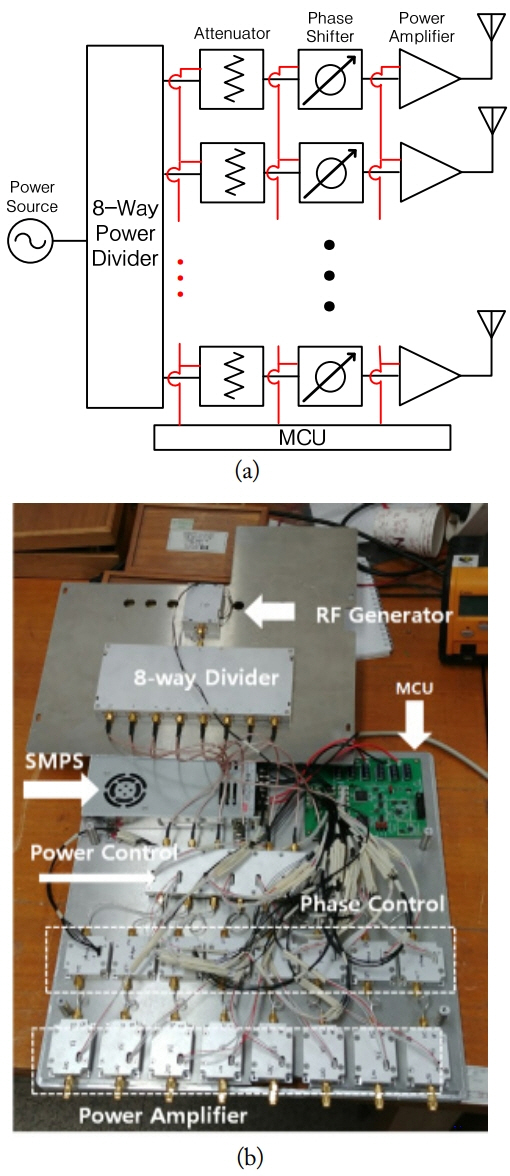
The entire structure of Tx system: (a) schematic of a 1 × 8 Tx array antenna system and (b) structure of a fabricated of 1 × 8 Tx array antenna system.
In Fig. 5, we show the setup for measuring the efficiencies. The 1 × 8 Tx microstrip patch antenna is located at a fixed position, and the Rx patch antenna is moved 1λ to 16λ away from the Tx in the broadside direction. The transmitting power radiated from one patch element is set to be 0.2 W, and the total transmitting power is 1.6 W (32 dBm). The MCU is programmed such that the fields radiated from the eight patch elements are coherently (in-phase) received at the Rx. The received powers are measured using a spectrum analyzer. The measured powers, shown in Table 1, decrease from 20 dBm to 6.2 dBm as R/λ increases from 1 to 16.

Measured Rx received power (f = 2.4 GHz, λ = 12.5 cm, Pt = 1.6 W = 32 dBm) as a function of the distance R
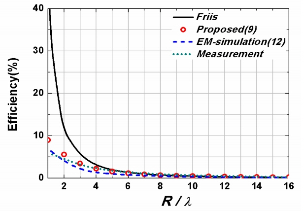
In Fig. 6, the measured efficiencies based on Table 1 are compared with the theoretical results of (9) and EM-simulated results of (12) results as R/λ increases from 1 to 16. In the case of the efficiency of (9), Gt has been obtained by taking into account the gain of each element in the direction of the receiver.
They are all shown to be in relatively good agreement. However, the efficiencies using the Friis formula (1) show significant differences when R/λ decreases.
V. Conclusion
In this letter, a new efficiency formula has been proposed for use in the near field as well as in the far field under the condition of coherent reception at the Rx. It has been found that the proposed formula agrees well with both EM-simulations and measurements. The proposed formula has also been shown to reduce to the Friis equation for far ranges, demonstrating its generality. The efficiencies for wireless power transfer or communications in the near and far fields can be simply evaluated with the proposed efficiency formula without time-consuming EM-simulations or measurements.
Acknowledgments
This research was supported by the Ministry of Science and ICT, Korea, under the Information Technology Research Center support program (No. IITP-2019-2016-0-00291) supervised by the Institute for Information & Communications Technology Promotion (IITP).
References
Biography

Yongwook Kim received a B.S. and M.S. in electronics engineering from Kyung Hee University, Yongin, Korea, in 2017 and 2019, respectively. His fields of research include microwave antennas, passive devices, and wireless power transmission.

Seunghyun Boo received a B.S. and M.S. in electronics engineering from Kyung Hee University, Yongin, Korea, in 2017 and 2019, respectively. His fields of research include microwave antennas, passive devices, and wireless power transmission.

Gunyoung Kim received a B.S. in Radio Communication Engineering from Kyung Hee University, Yongin, Korea in 2010, an M.S. in Electronics and Radio Engineering from Kyung Hee University in 2012, and a Ph.D. in Electronics Engineering from Kyung Hee University in 2018. Currently, he is a post-doctor in the College of Electronics and Information at Kyung Hee University. His fields of research include microwave antennas, passive devices, wireless power transmission, and metamaterials.

Bomson Lee received a B.S. in Electrical Engineering from Seoul National University, Seoul, Korea, in 1982. From 1982 to 1988, he was with Hyundai Engineering Company Ltd., Seoul, Korea. He received an M.S. and a Ph.D. in Electrical Engineering from the University of Nebraska, Lincoln, NE, USA, in 1991 and 1995, respectively. In 1995, he joined the faculty at Kyung Hee University, where he is currently a professor in the Department of Electronics and Radio Engineering. From 2007 to 2008, he was the chair of the technical group for microwave and radio wave propagation in KIEES (Korea Institute of Electromagnetic Engineering & Science). In 2010, he was the editor-in-chief for the Journal of the Korean Institute of Electromagnetic Engineering and Science. In 2018, he served as the president of KIEES. His research activities include microwave antennas, RF identification tags, microwave passive devices, wireless power transfer, and metamaterials.

Namyoon Kim received an M.S. and a Ph.D. in electronics and radio engineering from Kyung Hee University, Korea, in 2002 and 2012, respectively. From 2005 to 2013, he was with LG Innotek (LGIT) and the Samsung Advanced Institute of Technology (SAIT), in Suwon, Korea, where he served as a senior researcher in RFID, Ubiquitous Sensor Network, loosely coupled wireless power transfer, communication technology in wireless charging systems, and energy harvesting. He was working in the Intelligent Wireless Power Research Center (IWPRC) for wireless charging as a member of the IWPRC Group in 2015. Since 2017, he has been a professor at Daeduk University, Daejon, Korea. His research interests include RF characterization, Non-contact measurement of heart and energy-IT converging systems.
