Analysis and Modeling of GPR Signals to Detect Cavities: Case Studies in Morocco
Article information
Abstract
This research studied the detection of cavities and other abnormalities in subsoil utilizing ground penetrating radar (GPR) and an algorithm developed under MATLAB. The study also analyzed and modeled GPR signals to find the exact location of cavities in the subsoil. The algorithm was based on the finite difference time domain (FDTD) method to simulate cavities and compare them with an experimental study. This study used GPR with 400 MHz and 200 MHz to investigate and detect cavities. Three different areas were chosen with different proprieties of subsoil to detect the cavities: mountainous, coastal, and lowland areas. The results show high accuracy in the detection of cavities using GPR.
I. Introduction
In civil engineering, cavities and fragile areas are the most important obstacles in construction zones and quarries when deciding suitable places for using explosives [1]. In environmental, industrial, and urban construction points of view, the existence of cavities underground is a potential source of dangerous phenomena [2]. Ground penetrating radar (GPR) is a non-invasive subsurface prospecting technique based on the propagation of electromagnetic waves [3]. Its measurements are sensitive to dielectric permittivity variations between the cavity and the external environment [4]. The development of imaging to estimate the electromagnetic properties of the medium include the dielectric permittivity ɛ (F/m) and the electrical conductivity σ (S/m), which are critical issues for a physical interpretation of the target structures. Moreover, GPR is based on the transmission and reception of 10 MHz–2.6 GHz electromagnetic waves into the ground. The dielectric permittivity of the target overwhelms the permittivity of other soil components, and the presence of water in the soil principally governs GPR wave propagation. The system transmits a pulse in very short duration waves in the material and records the amplitude and time of arrival of each wave. Reflection waves are produced to the right of any changes in the properties of conduction of electric current in the middle (dielectric constant). Its amplitude is determined from the contrast of dielectric permittivity between the banking and the target. One part of the transmitted wave energy continues to spread in the middle until it is attenuated to be detected. The attenuation of the transmitted signal is extremely variable and depends greatly on the electrical conductivity of the materials. Any field with high electrical conductivity will very strongly attenuate the radar waves and vice versa [5, 6]. There are numerous applications for GPR radar in various research areas: geology, mining, environmental, geotechnical, civil engineering, hydrology, archeology, and others [1–3]. A high-resolution seismic reflection was used to detect and characterize underground cavities [2]. An experimental detection was also used [3] as a geophysical survey routine for the detection of doline areas in the surroundings of Zaragoza, using two techniques. The first was magnetometry and electromagnetic multi-frequency radiation to examine the entire survey area to determine anomalous subsoil behaviors; the second was GPR electric tomography, or seismic methods, to generate an indirect view of the subsoil structure to detect cavities [7, 8]. Cavity detection has been considered one of the primary targets in geophysical prospecting, representing a principal goal for the prevention of risk. For example, cavity detection in urban areas is important to prevent accidents related to possible collapses, and in archeology, these cavities are even more important [9]. Most of the techniques proposed lie in the detection of water or air-filled voids whose physical properties (density, electrical resistivity and conductivity, dielectric constant, magnetic susceptibility) are considerably different from the host sediment or rock [3]. In previous studies, the detection of cavities could not fully distinguish those cavities from others due to the similarity between certain materials and the properties of constant dielectric cavities and iron. In this work, we have developed a numerical program to present the amplitude of the buried object’s signal during exploration. The program has been effective distinguishing the cavities. In order to conduct a preliminary study of the signal’s characteristics of GPR reflections from cavities, numerical simulations were first studied using the gprMax program. This program is a GPR simulator based on the finite difference time domain (FDTD) method developed by Antonis Giannopoulos [4]. This method is widely used in various fields due to its generality and simplicity [10], such as using optical analysis for an optical device, including waveguide array and antenna analysis. The FDTD method discretized the electrical and magnetic fields into the dual lattice in space and time coordinates. However, the FDTD method is essentially based on the integral of Maxwell’s equations.
This paper examines cavity detection in different fields with experimental and theoretical simulation. The use of geophysical methods, such as GPR and seismic methods, provides an effective alternative for cavity detection. Our analyses of cavity detection were conducted with high precision at several location areas with different physical properties. To validate the accuracy of the experimental results, a numerical simulate was developed to detect the cavities. The theoretical and experimental results show high accuracy for using GPR and simulation for real applications in various fields. Also, GPR and the developed code can be used in several areas of civil engineering, such as for buildings and bridges, or to detect human bodies under ruins after earthquakes.
II. Theoretical Background
FDTD or Yee’s method is a numerical analysis technique widely used for modeling the dynamical system based in a differential equation [10]. To implement the FDTD method in Maxwell’ equations, a computational time domain must first be determined. Generally, the computational domain is the physical region over which the simulation will be performed or the area scanned with GPR.
The FDTD method is based on the numerical resolution of Maxwell’s equations expressed in cylindrical coordinates by following the adapted Yee scheme [11, 12], shown in Fig. 1(a).

Positions of the electric and magnetic field components according to the cylindrical Yee scheme in a 3D case (a) and the FDTD method (b).
The chart of the FDTD method is given in Fig. 1(b). The reflection of the strength created by GPR in a perpendicular incident wave depends on the contrast of relative dielectric constants across the reflecting boundary. The reflection coefficient RC can be expressed as in Davis and Annan [5, 13]:
where ɛ r 1 and ɛ r 2 are the relative dielectric constants of mediums 1 and 2, respectively. These constants are used in the calculation of dielectric constant ɛ r , according to the following equation using c as the speed of light (0.3 m/ns) and h as the depth:
III. Materials and Methods
1. Materials
The GPR experimental data were collected using a GSSI SIR-3000 device with two antennas, 400 MHz and 200 MHz, for the center frequency. These antennas were adapted to be used in different geological conditions. The main adjusted settings were the acquisition gains that were measured in signal/noise and time. A simulation was made to detect several cavities and distinguish them from others using different targets and different forms using RADAN 7 for data processing.
2. Description of the Antennas
The antennas used for this study were an RC loaded bowtie designed for the 300 MHz to 3 GHz frequency range, as described in [14]. Fig. 2(a) presents the geometry of the GPR antennas, constituted by two half-ellipses. The capacitive loading was designed in periodic slots cued on the antenna arms, and a graphite sheet of 1 mm thickness was placed over each arm to provide the resistive load. The antenna was fed using a vertical microstrip to parallel stripline transition. Fig. 2(b) illustrates the simulated and measured magnitude of the S 11 parameter for the RC bowtie antenna.
3. Mode Scan and Method of Prospection
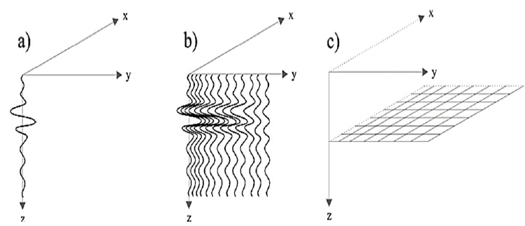
The experimental data obtained by GPR were analyzed and interpreted as an image of a vertical slice of the basement. The image was received by the concatenation of the A-scan and B-scan data recorded by GPR along the measured area [15]. Objects that fled the basement were marked by the presence of the hyperbole in the B-scan (Fig. 3(b)) and C-scan (Fig. 3(c)) [1].
IV. Results and Discussion
1. Cavity Detection in the Laboratory and Simulation
1.1 Comparison of simulation and experimentation results (1,600 MHz)
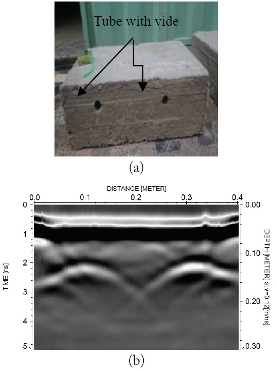
In order to simulate and measure the electromagnetic wave reflected by cavities and to validate the theoretical results obtained by the simulation, we created a laboratory experiment. We buried in the ground two iron bars (diameter of 16 mm) and two plastic tubes with vide (diameter 32 mm) that have dielectric permittivity of 7 F/m and conductivity of 0.001 S/m as shown in Fig. 4. The antenna we used had a central frequency of 1,600 MHz. Because the iron bar and the tubes had the same dielectric permittivity, we used empty tubes.
Fig. 5(b) shows the direct waves: the first strong amplitude is the combined reflection between the antenna and the reflected signal. It has a negative reflection coefficient due to the air between the antenna and the land surface. The amplitude difference at t = 1.4 ns is (1.4, 500) and at t = 1.8 is (1.8, −800) shows the effects of a cavity on the GPR signal.
1.2 Simulation of the cavity’s detection using 400 MHz
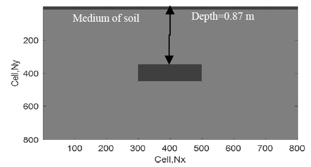
In this part of the study, we detected the cavity of a rectangular object (50 cm × 25 cm) presented in Fig. 6 using a simulation of GPR measurements. The response was from the surface buried in a homogeneous medium with a dielectric permittivity of 7, a conductivity of 10−3, and a depth of 0.87 m as shown in Fig. 5 by gprMax2D and MATLAB programs. Fig. 5(a) presented in the radargram shows the presence of hyperbola in Fig. 7(a) due to the total diffraction of the wave inside the cavity and its reflection at the end. Fig. 7(b) shows the evolution of the electric field. The amplitude E z of the electric field for the first travel time starts the diffraction for negative direction and then has a very strong diffraction in the other direction, due to the presence of the cavity, which has no conductivity.
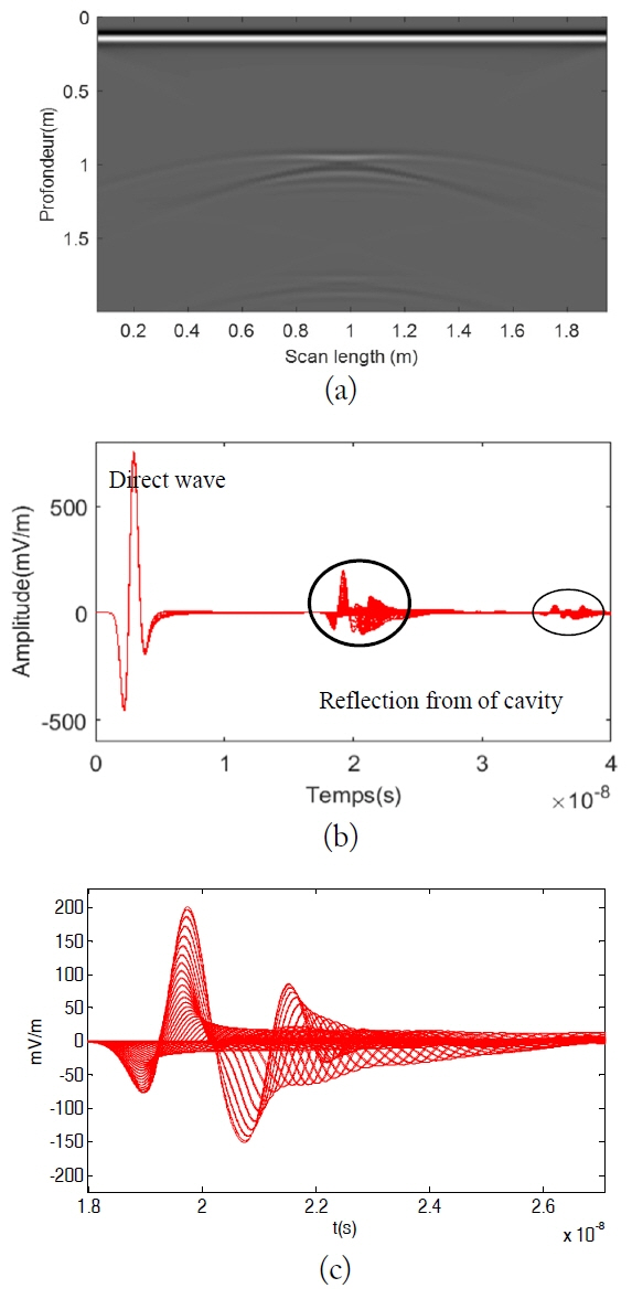
(a) Simulation to detect rectangular cavities, (b) trace amplitude of the wave reflection and refraction of the evolution of the electric field, and (c) zoom of (b).
Fig. 8(a) shows the simulation result for the detection of a square conductor target. We note that the hyperbola in this figure is clearly visible because of the conductivity of the target. Fig. 8(b) shows the results of modeling for detection of the conductor targets. The total reflection of the electric field amplitude E z is shown in the first travel time for the positive direction and then has a very strongly reflection in the other direction caused by high electrical conductivity.
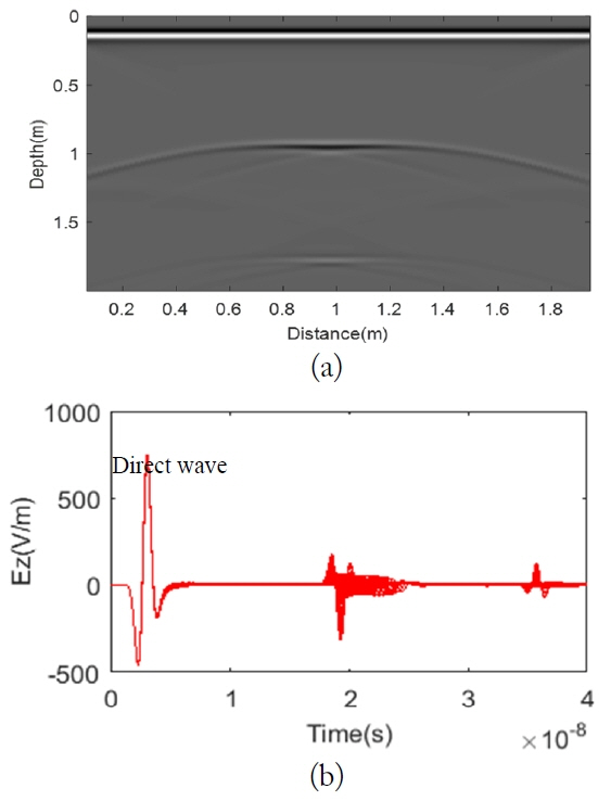
(a) Simulation to detect a rectangular conductor and (b) trace amplitude of the wave reflection and refraction.
Fig. 9(a) presents the simulated detection of a rectangular dielectric target. We observe that the hyperbolas in this case is less clear compared to the case of the conductor target. This is because the reflection and diffraction waves are approximately equal, and because the positive and negative amplitude are approximately equal, as shown in Fig. 8(b). In order to detect the difference between cavities and hyperbolas, the following conditions are used:

(a) Simulation to detect rectangular plastic and (b) trace amplitude of the wave reflection and refraction.
The dielectric constant of the cavity is equal to one and the conductivity is zero;
The hyperbolas of the cavity are in white and black;
The amplitude of the signal has a minimal value in the negative direction and a maximum value in the positive direction.
2. Results of Investigation of Cavities in a Subsurface in Homogeneities using Data Acquisition
This section uses three GPR surveys perpendicular to the ground in three different areas. We measured the GPR data in the mode of prospection (common measure point). The results shown in the radargrams are represented by the distance on axis X and the depth on axis Y.
2.1 Cavity detection in a mountainous area: a quarry in Khamis Anjara
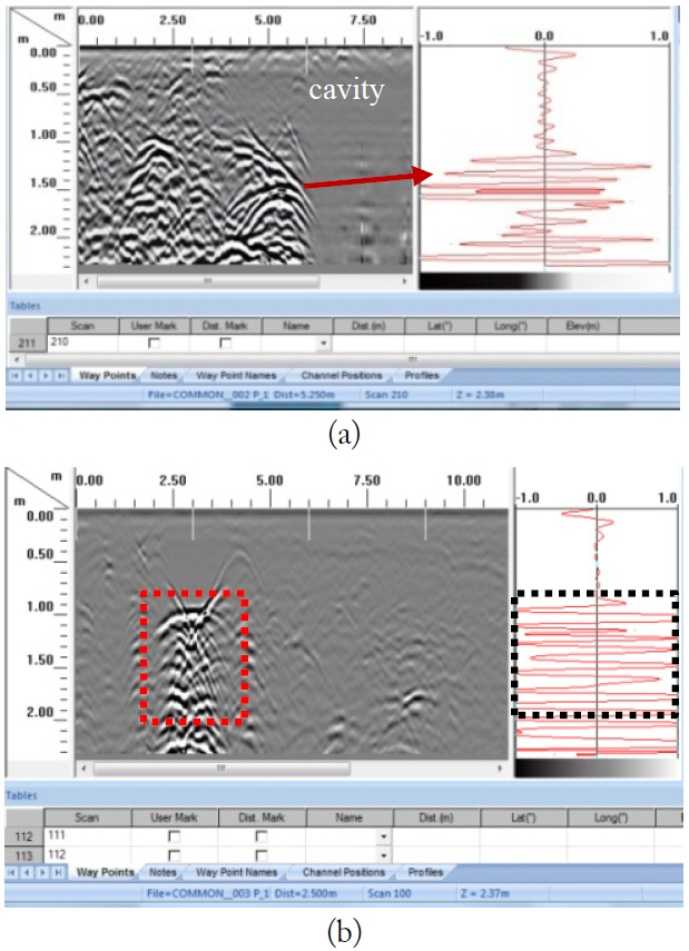
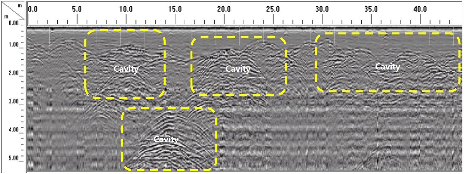
The importance of this cavity detection in quarries is to identify suitable areas for the placement of explosives during the production of gravel, sand, and other elements. This is the basis of all construction in civil engineering. It is necessary to locate these cavities and to record their coordinates with precision on the ground so as to designate future areas for explosives and to avoid fragile zones and cavities. If the explosives are placed in cavities or fragile ground, there will be no explosion, causing loss of money, effort, and time. The stone quarry located next to the village of Khamis Anjara in a region of Tetouan city was used in this study.
In Fig. 10(a), the cavity extends from 0.5 m to 5.3 m and the depth ranges from 1 m to more than 2.5 m.
2.2 Cavity detection in a flat area (road project)
The aim of this survey in this area is to detect cavities in an urban area. A cavities were found during work on the construction of a new road project. In this zone, a GPR survey was conducted at a survey distance of 1,000 m and a depth of 6 m.
2.2.1 Methodology
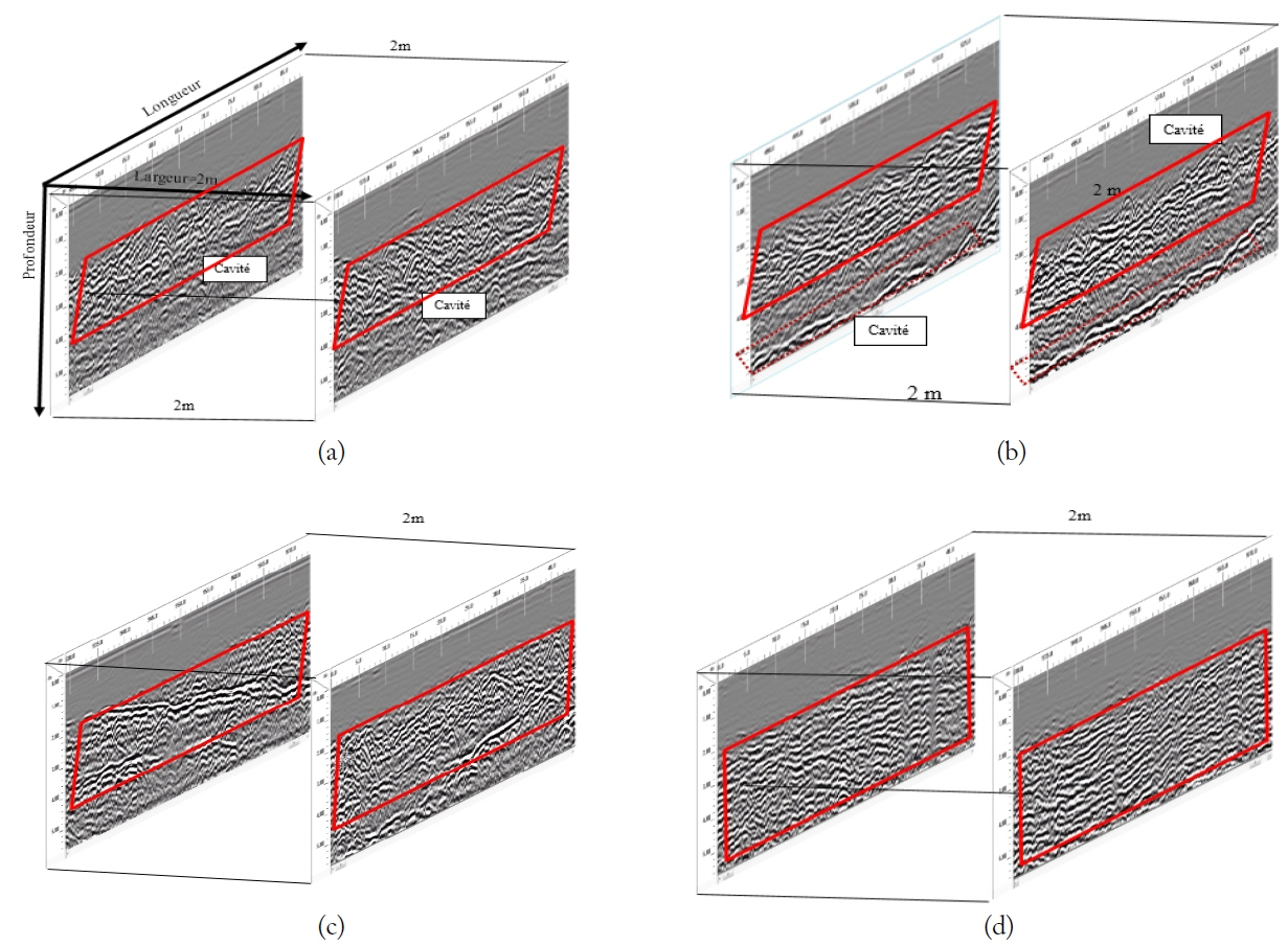
In this part of the study, an antenna with 200 MHz was used to detect an object at 8 m depth in the road. The results are given in B-scan mode. The road (El Jadida-Safi, 143 km) was divided into four 4-km-long profiles for each investigation (Safi-El Jadida). The distance between each profile was 2 m (Fig. 11).
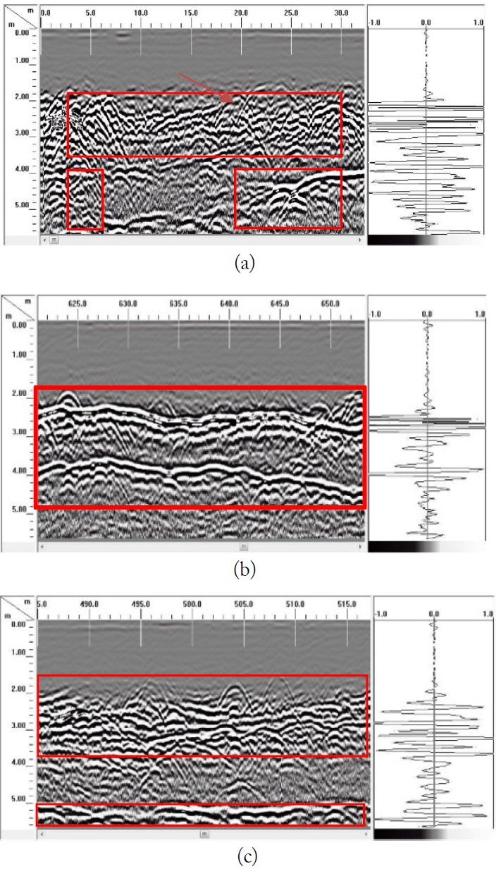
The radar profiles show an overview of the studied site, with 3D profiles acquired along the road and illustrating the contrast below the surface on different sections of the road. In order to facilitate the reading of the radargram, the red squares of the zones of reflections and diffractions represent cavities. The three areas where we found a long cavity were more than 5 km. The specific areas that were considered in this study have a length of 1 km per area, divided into several radargrams, where we could not present all the data (information about targets). Two-dimensional and 3D investigations are described and presented below. Furthermore, the simulation of cavity detection in the fourth section by the signals and radargram was applied, and the work confirmed the results.
2.2.2 Investigations in zone 1B-scan mode (2D)
At the beginning, we carried out 2D investigations that began from 246 km to 247 km of the road. In the first zone (Fig. 12), we chose to investigate deep cavities at a depth different from 2.2 m to 6 m.
Fig. 12 shows a GPR image obtained on the ground. At the travel time of 120 ns and depth of 6 m, a strong reflection was detected, which is considered the electromagnetic wave reflected from the cavity. In Profile 1, there are cavities from 0 m to 30 m. In Profile 2, there are cavities from 600 m to 660 m. In Profile 3, there are cavities from 485 m to 520 m.
2.2.3 3D investigation of zone 2 by C-scan modes
In this part of the study, we carried out 3D investigations on lengths of 1 km and 6 km, respectively, divided into several radargrams and at a depth of 5m and a width of 2 m.
The second zone begins from 251 km and 252 km as a length of the road at 3 km shown in Fig. 13. The coordinates of zone 2 are at depth different from 2.2 m to 6 m, length along 251–252 km (1 km), and width is 2 m.
2.3 Cavity detection in a coastal area: Harhoura
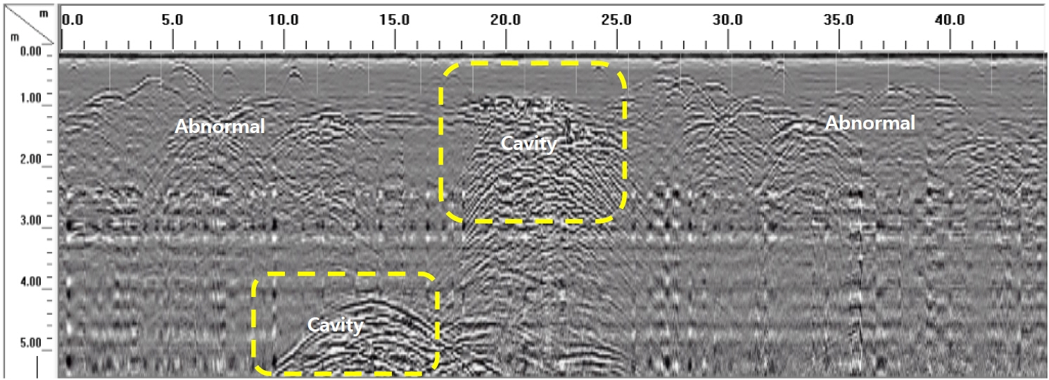
For this part of the study, we positioned the radar profiles as shown in the map below. On the basis of indications of the plan in Fig. 14, we indicate the various anomalies by area. The different profiles performed in this area show that several areas have empty attendance indices, soil destructuration, or simple fractures with small voids. The profile in Fig. 14 shows an evolution of anomalies with a fracturing of the subsoil that connects the two anomalies. The first anomaly evolves in depth with the presence of empty franc, an increase of the surface of the third anomaly with the presence of a vacuum, and the presence of a 1m deep fracture that connects the two anomalies with a scattered void.
The profile in Fig. 15 shows an evolution of anomalies and fractures with the presence of voids throughout the profile length and shows the presence of a significant cavity starting from a depth of 4.5 m. The profile of Fig. 16 shows continuity of the deep cavity with an increase in the volume of the anomaly detected at the surface, mainly for the anomaly above the cavity, with ramifications between them. We will indicate the results of the additional auscultation that we have achieved to determine the maximum depth of the cavity detected in zone 1.
We carried out radar profiles of deep cavity detection areas in order to define in depth as seen in Figs. 14 –16. The radar profiles carried out on that cavity could reach 15 m deep into usable signals on this depth, and we have delimited the cavity at 8.20 m depth. Beyond 8.20 m deep, the pitch becomes homogeneous.
V. Conclusion
In this work, we conducted numerical and simulated results, as well as experiments and surveys in mountainous, flat, and coastal areas. We found great similarity between the results from our modeling and the experimental results and field surveys. We have been able to identify cavities in subsoil in an effective and successful way. We observed that the hyperbola resulting from the reflection of waves from the cavities in coastal areas is very thin (faint) and different from the other regions due to the high humidity in this area. Also noteworthy is that the hyperbolas are insufficient to identify cavities so the use of an amplitude of reflected waves is needed. The results obtained show the presence of cavities at different distances and depths in the places studied. It is noted in this study that the depth of the investigations reached 8 m using a 400 MHz antenna, which can indicate that the ground has distinctive characteristics and very low conductivity. The detection of the cavity in the coastal area was difficult compared to the mountainous and flat areas, which were easier and more obvious.
References
Biography
Gamil Alsharahi was born in Amran City, Yemen, in 1979. He obtained a Bachelor of Mathematics and Master of Electronic & Telecommunication degrees at University Sana’a, Faculty of Science, Amran, and Abdelmalek Essaadi University, Faculty of Science, respectively. He also holds a Ph.D. in Electronic & Telecommunications at the Faculty of Science, Tetouan. As a Ph.D. student, he visited Ovidius University of Constanta, Romania, at the Faculty of Civil Engineering in 2019. He has two books and over 28 scientific papers published in different journals and conference proceedings.

Mohamed Bayjja was born in Errachidia, Morocco, in 1982. He earned mastery (Bac +4) in Computer Science, Electronics, Electrical, and Automatic from the Faculty of Science and Technology, Errachidia, Morocco, in 2007. He also received a Master degree in 2011 and a PhD degree, both in Electronic & Telecommunications from Abdelmalek Essaadi University, Morocco. He is preparing a postdoc at the Faculty of Electronics, Telecommunications and Information Technology, Cluj-Napoca in Romania. He authored or coauthored more than 13 publications in international journals and conference proceedings.

Ahmed Faize was born in Morocco in 1985. Currently, he is a professor and researcher at Mohammed 1st University, Faculty Polydisciplinarly, Nador, Morocco.

Mohamed Louzazni obtained a Bachelor of Electronic and Master of Electronic & Telecommunication degrees at the University Ibn Tofail, Faculty of Science, Kenitra, Morocco, and Abdelmalek Essaadi University, Faculty of Science, respectively. He also holds a Ph.D. in electrical and renewable energy engineering at the National School of Applied Science, Tangier. He was a Ph.D. student visiting the University Polytechnic of Bucharest at the Faculty of Electrical Engineering in 2015. In 2017, he started research at the University Polytechnic of Milan, Italy at the Solar Tech laboratory in the Energy Department. In 2018, he was a Ph.D. visitor at the University of Cadiz at the Higher Polytechnic School of Algeciras, Spain, for 5 months. Currently, he is a researcher at the University Polytechnic in Milan.

Carmen Maftei is Professor at the Civil Engineering Department of Ovidius University in Constanta, Romania. She attended the Polytechnic Institute of Iasi where she majored in Land Reclamation in 1988. From 1996 to 1998, she specialized in water resources and protection of water resources, equivalent to a Master of Science. In 2002, she finished her Ph.D. studies in Water Science in Continental Environment. Her research activities focus on: hydrology and hydrological modeling; geographic information systems applications in environmental sciences; and remote sensing applications in environmental sciences. She has written 11 books and book chapters, over 90 scientific papers published in different journals or conference proceedings, one patent, three international projects, 17 national grants, and 13 research contracts with economic partners. She is a member of many editorial boards of scientific journals. Her 25 years of teaching experience includes hydrology, hydraulics, and geographic information systems and applications at Ovidius University of Constanta and Transilvania University of Brasov in Romania.

Abdellah Driouach was born in Al Hocei-ma City, Morocco, in 1954. He received his license in electronic physics at the University of Rabat (Morocco) in 1979, his doctorate in spectronomiehertzienne at the University of Bordeaux 1 (France) in 1983, and his Ph.D. in sciences at the University of Grenade (Spain). He has been a professor and researcher in the Faculty of Science, Abdelmallek Essaadi University since 1983. He has participated in several scientific research studies, including the dispersion of electromagnetic waves on obstacles to arbitrary structures. Currently, he is a member of the research team of communication systems.

Abdellatif Khamlichi was born in 1963 in Northern Morocco. He has made his studies in Morocco and France. He was graduated as Ph.D. in Mechanics at Ecole Centrale of Lyon in France in 1992. Before that he was graduated in 1998 as Civil Engineer at the National School of State Public works which is located in Vaulx-en-Velin in France. He is now professor at the National School of Applied Sciences of Tetouan in Morocco. His main research activity was dedicated to civil and mechanical engineering. Among the topics he has worked on there are: waterhammer in piping systems, fluid-structure interaction, piezoelectric actuators, crashworthiness, friction products, composites, stability of shells, internal erosion, thermomechanical fatigue, control of wind turbines, seismic vulnerability, building reinforcement, inverse problem, structural health monitoring, non-destructive evaluation, GPR, soil-structure interaction. He has published more than 44 scientific articles in Scopus indexed journals and about 54 Scopus indexed conference papers. He has also advised more than 20 PhD theses.


