Optimization Methodology of Multiple Air Hole Effects in Substrate Integrated Waveguide Applications
Article information
Abstract
A wide spectrum of potential applications using substrate integrated waveguide (SIW) technologies in conjunction with air hole regions is introduced, and an efficient optimization methodology to cope with the multiple air hole effect in SIW applications is proposed. The methodology adopts a genetic algorithm to obtain optimum air hole dimensions for the specific propagation constant that can be accurately calculated using the recursive and closed form equations presented. The optimization results are evaluated by designing an SIW bandpass filter, and they show excellent performance. The optimization methodology using the proposed equations is effective in performance enhancement for the purposes of low loss and broadband SIW applications.
I. Introduction
Over the last decade, intensive studies in various substrate integrated waveguide (SIW) application areas have been conducted because of the benefits of this technology, such as high quality factor, high power-handling capability, high density integration, low cost, and easy fabrication. These benefits have successfully demonstrated their potential to enhance wireless communication performance [1–9]. These studies were possible thanks to a well-established theory of SIW that gives a highly accurate transfer equation for obtaining an equivalent modeling to conventional rectangular waveguide (RW) filled with dielectric material [10–14].
It should be noted that SIW can be a more attractive solution for designs below 6 GHz with compact size, exploiting the merit of the conventional RW [6, 7].
On the other hand, the explosive demand for cellular data requires increased capacity and spectral efficiency of wireless communication networks, which in turn is leading and stimulating network evolution to 5G systems that will require additional high frequency bands above 6 GHz [15]. In particular, millimeter-wave (mm-wave) around and above 30 GHz is a promising candidate, with extensive wide bandwidth supporting the ever-growing data rates needed [15]. In order to achieve the required performance using the mm-wave (as well as below 6 GHz), massive MIMO and multibeam antenna systems should be developed and deployed; low loss interconnections/filters, broadband phase shifters, and massive array antennas are essential technologies. Therefore, the SIW described above will be one of the core solutions for meeting these requirements [16, 17].
Low loss components such as transmission lines, filters, and broadband phase shifters based on SIW technology have been proposed, along with their structure and fabrication process [18–23]. The SIW structures proposed in previous studies have introduced an air-filled region by partially eliminating substrate to change the dispersion characteristics (i.e., cut-off frequency and phase) and reduce the dielectric loss. An interesting study [24] hypothesized and proved that unimodal operation bandwidth can effectively be increased by adjusting the size and location of the air region. In addition, the radiation efficiency and bandwidth of a slot antenna were successfully improved by forming an air region in the area of the slot radiator [25].
Although the SIW combined with the air region can be widely used as described, only a few studies have suggested analytical approaches and modeling for analysis of the air effect in SIW. In [24], highly accurate numerical calculations using the boundary integral-resonant mode expansion (BI-RME) method were proposed for the analysis of a periodically perforated dielectric medium. In [19, 22], frequency independent effective permittivity was extracted using the commercial software tool, ANSYS HFSS (Electromagnetics Suite version 18.0), for monomode regime (TE10) only. It is noteworthy that research for the optimization of the air hole design to a target value has not yet been carried out.
This paper presents an optimization methodology of the air hole effect for high-performance SIW applications. In Section II, we introduce two efficient equations for analyzing the multiple air hole effect in SIW, where the wave equation and the electric field distribution profile in the TE mode regime were considered. Section III shows the optimization concept and procedure using a genetic algorithm (GA) combined with analysis equations to extract the optimum air hole structure for the desired propagation constant. We verified the optimization performance by designing an SIW bandpass filter (BPF) and comparing it to the ideal equivalent model (Section IV). The SIW BPF with optimized air hole structure was simulated by the HFSS, and the results were in excellent agreement with the ideal model. Hence, we expect that this approach can provide an efficient optimization methodology for designing low loss broadband SIW circuits, including slot array antennas, for obtaining the optimum performance in microwave and mm-wave frequency range applications.
II. Analysis of the Air Holes in SIW
1. Structure Approximation
Fig. 1 shows the section of SIW with an arbitrary number of circular air holes and the unit cell of the SIW in the x-z plane. The structure is characterized as follows: SIW width aSIW, air hole diameter dh,k with the centric position x0k, unit cell length luc, number of air holes N, and height of SIW b The shorting via hole diameter dv and the separation sv are given by the condition 0.05 < sv/g < 0.25, sv > dv [12], and λg is the guided wave length. aeff is the effective width of the equivalent RW and is given by [26].
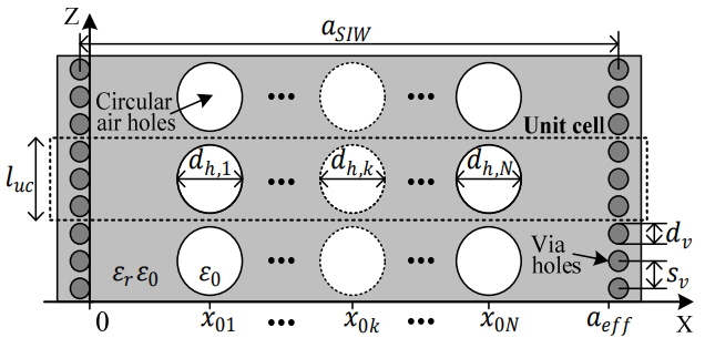
Section of SIW with arbitrary number of circular air holes and unit cell.
Fig. 2 represents the approximated equivalent structure in the x-z plane and the x-y plane to facilitate a simple but accurate analysis of the air hole effects.
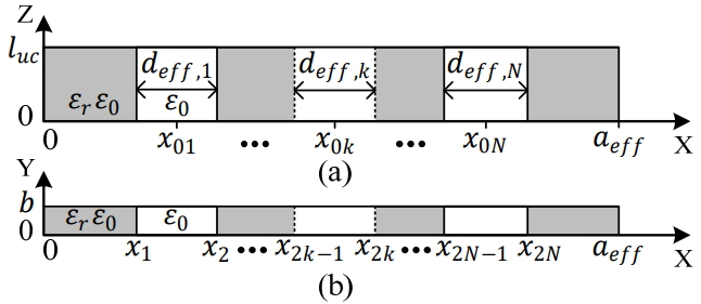
Approximated equivalent structure in x-z plane (a) and x-y plane (b).
In the approximation, the circular air hole in Fig. 1 has been converted to a rectangular shape to have an equal volume of air in the unit cell. Hence, the relationship between Figs. 1 and 2 can be derived by Eqs. (2)–(3):
In this study, we considered the air hole that was closed by a conductor on the top and bottom plane of the SIW, so the structure does not have any radiation effect through the holes.
2. Recursive Equation for SIW with Multiple Air Holes
The recursive equation for the estimation of phase constant β of the structure in Fig. 2 has been derived and proposed by the author [27]. The equation was successfully derived from the wave equation for the case of the partially loaded waveguide [28], which is simple but accurate. As a result, the recursive equation for the phase constant β can be represented by Eqs. (4)–(7).
where
where
3. Closed Form Equation for the Effective Dielectric Constant
The effective dielectric constant (ɛr, eff) in the SIW with air holes is mainly subject to E-field distribution in transverse mode of wave propagation. The theory suggests that the combination of the air and dielectric media in the SIW will distort the E-field distribution profile to satisfy the boundary and phase matching condition at the interface of two different media, which will result in an increase in complexity for exact analysis. In this study, however, an approximation was used, neglecting the boundary and phase matching condition, because the E-field profile is not so significant a distortion when the operating frequency approaches the cut-off region. In this section, therefore, we proposed the closed form equation for the ɛr, eff from the E-field energy equivalence concept, on the assumption that the wave number and the E-field amplitude is equal to the conventional SIW filled with uniform dielectric material. We can finally obtain the closed form equation of ɛr, eff for Fig. 2(b) in Eq. (10), combining Eqs. (8) and (9).
where, Wh, Wd, Wa, and Weff represent the total time-average stored electric energy, the energy in dielectric, air, and equivalent dielectric media, respectively, and kc = π/aeff is the cut-off wavenumber of the SIW filled with uniform dielectric material.
4. Efficient Method for Solving the Recursive Equation
Recursive Eq. (6) can be expressed as Eq. (11) for finding minima, and ka and kd can be expressed in terms of β using Eqs. (4) and (5). The root of Eq. (11) can be solved numerically for β using the Newton-Raphson method.
Fig. 3 shows the typical characteristic of Re[fs(β)] for solving the phase constant, and the initial value β0 is needed for the finding of minima. We need an initial value as close as possible to the root for the fast convergence of Eq. (11), and the closed form Eq. (10) was therefore used to obtain the initial value β0.
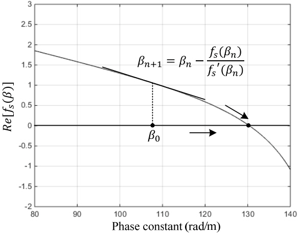
Re[fs(β)] for solving phase constant β.
5. Calculation Results
Four structures that have different numbers of air holes (1, 3, 5, and 7 holes) were considered and calculated to verify the agreement of the ɛr,eff extracted at cut-off frequency by means of the proposed approaches. The results were compared with simulated results from the eigenmode solver in the HFSS. We assumed Taconic/RF30-7H substrate properties with ɛr = 2.97, height h = 0.762 mm and aeff = 28.87 mm, b = 0.762 mm, dv = 1 mm, sv = 1.4 mm varying the air hole diameter dh,k from 0.6 mm to 3.6 mm and the unit cell length luc =dh,k+ 0.6 mm. The air hole position for each number of holes is shown in Table 1. All dh,k are identical, and the gap between the air hole in unit cell is set to 0.3 mm.
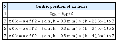
Position of air holes
Fig. 4 shows the results for ɛr,eff using the three methods along with the air hole diameter variation, which shows excellent agreement with the proposed approaches (within 2% error for the analysis scope).
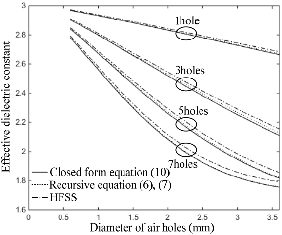
Effective dielectric constant at the cut-off frequency of SIW with multiple air holes (N = 1, 3, 5, 7).
III. Optimization Using Genetic Algorithm
A GA was applied for SIW optimization, in which the air hole diameters dh,k, number of holes N, and number of cells Ncell were the variables. We show how the GA is applied when the number of holes is fixed, and then we extend this to the case where the number of holes is variable.
1. Restricted Tournament Selection
Restricted tournament selection (RTS) is a multimodal GA [29] that is able to maintain a diverse population throughout the evolution process. Diversity is a critical feature needed in GAs in order to avoid premature convergence. Previous studies show the advantage in performance of RTS compared to other GAs [30, 31]. The algorithm is summarized as follows:
From the population, pick two parents, A and B.
Cross over and mutate A and B to produce offspring, A′ and B′.
Pick a subpopulation of w chromosomes from the population.
Find the chromosome that most resembles A′ from the subpopulation and let it compete for a place in the population.
Repeat steps 3 and 4 for B′.
The above process is repeated until a certain stopping criterion is met; such a criterion can be a time limit, convergence of fitness value, fitness value exceeding a threshold, etc. Further details are discussed in the rest of this section.
2. Chromosome and Fitness Function
For a case with N holes, a vector of N+1 double-precision floating-point numbers represents a single chromosome. The first number in the vector represents the number of cells. The rest of the number represents the hole diameters. The (i + 1)th gene represents the diameter of the ith hole. The population is simply a 2-D array of size (N+1)×Np, and Np is the size of population. Note that the first gene of the chromosome does not need to be a floating-point number; this choice was made for the sake of simplicity.
Initialization of a population can be carried out by setting the first gene of every chromosome to U{Ncell,min,Ncell,max} and the rest of the genes to U(dh,k,min,dh,k,max), where U{a,b} and U(a,b) are discrete and continuous uniform random variables in the ranges [a,b] and (a,b), respectively, ncell,min is the minimum number of cells, ncell,max is the maximum number of cells, dh,k,min is the minimum diameter of a hole, and dh,k,max is the maximum diameter. The fitness function, which assigns a value of fitness to a chromosome, is defined as follows:
where xi is the ith chromosome, T is the target value, and we can freely assign this value (i.e., the phase constant or effective dielectric constant etc. can be selected), and g(xi) is a computer function that computes the wavenumber for xi. The chromosomes that have wavenumbers closer to the target have higher fitness values. This fitness function directs the evolving population toward the configurations that have the target wavenumber. The population stops evolving when a given computation time is exhausted or the solutions have converged.
3. Variable Number of Holes
For the case with variable number of holes, the chromosome length will also vary. There are GA schemes to deal with variable-length chromosomes, but in order to avoid this extra complexity and avoid an increase in the optimization time, parallel multiple populations are evolved independently, with each population representing a single number of holes. After the evolutions have finished, all populations are evaluated using the fitness function, and the top solutions can be found by sorting them according to their fitness values.
4. Genetic Operators
Since the chromosome consists of both positive integers and real numbers, it is convenient to deal with these separately. For integers, given their small magnitudes, one-point crossovers and random bit flip mutations were performed on their unsigned binary representations.
For genes with real numbers, genetic operators that deal with real numbers effectively were used. Blend crossover [32] was used to cross over the two parents, as shown in Eq. (13)
where xi and yi are the ith genes of two parents, assuming xi <yi, zi is the ith gene of the offspring, and α is a factor that controls the expansion. α = 0.5 was used.
Gaussian mutation [33] is an effective mutation method for real-coded GAs. It is applied with a mutation probability pm, and its operation is given by
where xi is the ith gene before mutation, and N(0, σ2) is a Gaussian random variable with mean 0 and variance σ2. The extent of the disruptiveness of mutation can be precisely controlled with the probability and variance. pm =1 and σ2 = 8.33×10⁻⁴(dh,k,max − dh,k,min) were used in this study.
5. Optimization Results
Optimization was carried out to find SIW parameters when the target is phase constant β, in which the air hole diameters dh,k and number of holes N were the variables. The number of cells Ncell was fixed to 1 for convenience. We used Taconic/RF30-7H substrate properties with ɛr = 2.97, height h = 0.762 mm, aeff = 28.87 mm, luc = dh,k + 0.6 mm and a gap between the air holes in the unit cell of 0.3 mm.
Table 2 shows the optimization results according to the score rank when the target value of β is 80 rad/m and the errors in percentage indicate the difference between the optimized and target values of β. Several types of solution are suggested in Table 2, and they show good agreement (less than 2.1e-8% optimization errors). The optimization process took about a minute using a typical laptop computer.
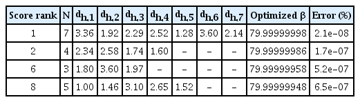
Optimization results by genetic algorithm when the target value was β = 80 and Ncell was fixed to 1
IV. Validation by Bandpass Filter Design
The high impedance waveguide sections in SIW can be realized by the introduction of multiple air holes, as the effective dielectric constant of SIW can be lowered by the partially removed dielectric regions. The high impedance waveguide sections operating below the cut-off frequency can be used as an impedance inverter. Fig. 5 shows the 5th order equivalent BPF model, which consists of a half-wave resonator with a low impedance section separated by the high impedance coupling sections. The K inverter value can be extracted by the T network equivalent circuit model and the scattering parameter of high impedance sections [34].

Equivalent model of 5th order bandpass filter.
A previous study introduced the design method of this filter based on the analytical method and the filter design parameters that were extracted by the EM simulation [22]. There is a limit to this approach for obtaining accurate dimensions with a target K inverter value, because numerous EM simulations are needed to find well-matched dimensions of air hole diameters dh,k, number of holes N, and number of cells Ncell. In this paper, a very accurate approach is applied to find the dimension of the filter by means of the recursive equation and optimization by GA.
For the validation, the 5th order BPF was designed with 4 GHz center frequency and 600 MHz bandwidth, with the introduction of multiple air holes as an impedance inverter. The element values of the 5th order Chebyshev low pass filter with 15 dB return loss (0.14 dB ripple) were used, and the impedance inverter factor Kn−1,n/Z0 was obtained from [34]. We used Taconic/CER-10 substrate properties with ɛr = 10, height h = 0.635 mm and aeff = 15.8 mm, aeff= 16.34 b = 0.635 mm, dv = 0.7 mm, sv = 0.95 mm luc =dh,k+0.25 mm, and the gap between the air hole in unit cell was set to 0.25 mm. The number of air holes N was fixed to 7, and the diameters of seven air holes dh,k were set to equal values for design convenience. Table 3 shows the desired values for the propagation constant βn and the effective dielectric constant ɛr,eff,n corresponding to the Kn−1,n/Z0 values. The optimization results from the GA for the number of unit cell Ncell, air hole diameter dh,k, half-wave resonator length lr,n, and coupling length lc,n are also shown in Table 3.
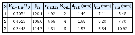
Optimization results by genetic algorithm
Fig. 6 shows the 5th order band pass filter implemented in SIW with multiple air holes, with the RW interface and the microstrip interference using tapered transition to excite the TE10 mode [35].
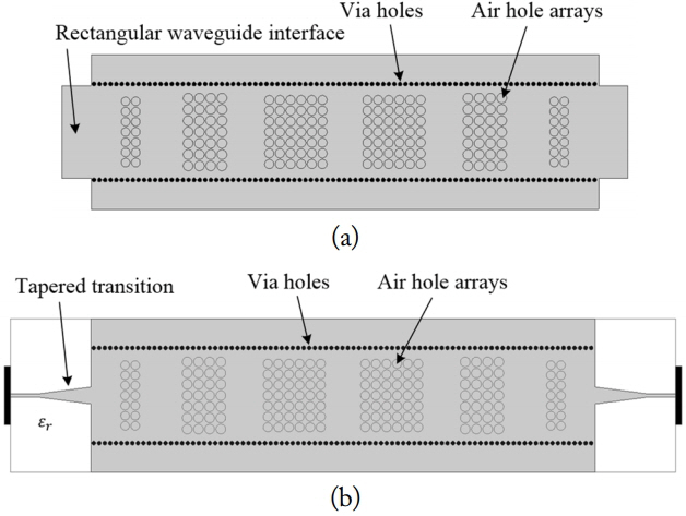
Fifth order bandpass filter implemented by SIW with multiple air holes. (a) Rectangular waveguide interface and (b) microstrip interface using tapered transition.
The results simulated (by HFSS) for the designed 5th order BPF using RW interface (without transition) and the ideal RW equivalent model are presented in Fig. 7, which shows excellent agreement over the entire frequency band. In the case of the microstrip interface with transition, a slightly different response is shown by the parasitic effects of tapered transition [36].

HFSS simulation results of 5th order band pass filter.
V. Conclusion
This paper proposes a novel optimization methodology for the multiple air hole effect for high-performance SIW applications by adopting a GA that is combined with highly efficient analysis equations of the air hole (i.e., recursive and closed form equations). In order to verify the optimization performance, a 5th order SIW BPF with multiple air holes for realizing the high impedance section was designed using the proposed method and simulated by the HFSS. The results are compared to the ideal equivalent model and show close correlation and excellent agreement.
Therefore, we expect the findings of this study can provide an efficient and accurate optimization methodology for the design of low loss broadband SIW circuits to optimum performance in microwave and mm-wave frequency range applications.
References
Biography
Jin-Yang Kim received B.S. and M.S. degrees in Electronics Engineering in 1999 and 2001, respectively, from Ajou University, Suwon, Korea, where he is currently pursuing a Ph.D. degree in Electronics Engineering. He works for Ace Technologies Corp., Incheon, Korea as its Chief Operating Officer. His current research interests include the modeling of SIW, SIW applications (filter, diplexer, transformer, phase shifter, etc.), and the integration of electromagnetic band gap structures to SIW.

Dong-Wan Chun received B.S., M.S., and Ph.D. degrees in Electronics Engineering in 1999, 2001, and 2006, respectively, from Ajou University, Suwon, Korea. Since 2006, he has been a team leader in advanced filter technology at Ace Technologies Corp., Incheon, Korea. His current research interests include the high power coaxial resonator filter, multi-mode dielectric resonator filter, waveguide filter, and passive components.

Christopher Jayun Ryu received B.S. and M.S. degrees in Electrical Engineering in 2012 and 2015, respectively, from the University of Illinois at Urbana-Champaign. Since 2015, he has been a research engineer at Ace Technologies Corp., Incheon, Korea. His current research interests include applying search and optimization techniques to solve microwave optimization problems and automation of microwave filter design processes.

Hai-Young Lee received the B.S. degree in Electronics Engineering from Ajou University, Suwon, Korea, in 1980, the M.S. degree in Electrical Engineering from the Korea Advanced Institute of Science and Technology (KAIST), Daejeon, Korea, in 1982, and the Ph.D. degree in Electrical Engineering from the University of Texas at Austin, TX, USA, in 1989. From 1982 to 1986, he was with the Ministry of National Defense, Seoul, Korea, as a Senior Research Engineer, where he was involved in the fields of electromagnetic compatibility and wave propagation. In 1998, he was a Visiting Professor at the University of California Los Angeles, CA, USA. From 1990 to 1992, he was the Head of Advanced Research Division 1 (Compound Semiconductor Devices Division) at the LG Electronics Institute of Technology, Seoul, Korea. He served as the Chairman of IEEE Microwave Theory and Techniques Society (Korea Chapter) from 2004 to 2007. Since 1992, he has been with the Department of Electronics Engineering, Ajou University, Suwon, Korea, as a Professor. In 2010, he served as President of the Korean Institute of Electromagnetic Engineering and Science (KIEES). He also served as the President of the User Council at the Korea Advanced Nano Fab Center (KANC) from 2005 to 2010. He founded the GigaLane Company, Gyeonggi-do, Korea, in 2001, and managed it as President until 2006. His current research interests lie in the fields of microwave and millimeter wave applications of SIW, system-on-a-package, high-speed interconnections and EMI/EMC for digital applications, and RFIC design and testing.