Compact Dual-Band Bandpass Filter Using U-Shaped Stepped-Impedance Resonators with Parallel Coupled Structures
Article information
Abstract
This paper proposes a dual-band bandpass filter using stepped-impedance resonators (SIRs) with parallel coupled structures. The proposed filter adopts U-shaped SIRs with parallel coupled lines (PCLs) that have interdigital and comb-line shorted ends. The central PCLs build an upper passband and a transmission zero, and the two U-shaped SIRs build a lower passband. Four resonators and coupling structures are theoretically analyzed to derive its scattering parameters. A novel dual-band bandpass filter is designed and fabricated using the induced scattering characteristics. The measured results show that the fabricated dual-band bandpass filter has an insertion loss of less than 1.02 dB in the lower band of 2.45 GHz and of 3.01 dB in the upper band of 3.42 GHz, and a band-to-band isolation of more than 40 dB, from 3.14 to 3.2 GHz.
I. Introduction
Various wireless/mobile communication systems require multi-service and/or multi-band applications to overcome expansion in the quantity of communication traffics. Microwave multi-band bandpass filters (BPFs) are important and essential components to satisfy such demands. To lower the fabrication cost and raise the performance, microstrip multi-band BPFs have been developed with compact sizes, large out-of-band rejection, and high selectivity.
Many microstrip multi-band BPFs have been implemented using multi-mode resonators (MMRs), coupled lines (CLs), etc. Some of MMR filters used square ring loaded resonator [1], stub-loaded quad-mode resonator (QMR) [2–5], and a QMR with source-load coupling [6]. A single QMR with parallel coupling microstrip lines was also introduced to implement dual-band BPFs [7]. Compact dual-band interdigital BPF has been achieved by using hybrid resonators with series and shunt resonances [8]. Some authors have proposed to design dual-/triple-band filters using asymmetrical CLs [9] or using CLs and grounded stepped impedance resonators (SIRs) [10]. Recently, the dual-band BPFs with high selectivity have been introduced using two different resonators [11], and U-shaped resonators [12]. Composite coupling structure for coplanar waveguide/microstrip [13] and complementary split-ring resonators with complementary spiral resonator [14] have been adopted in the development of dual-band BPFs.
In this paper, we present the design of a dual-band BPF using SIRs with parallel coupled structures. The even/odd-mode input admittances of the proposed structures are derived and the transfer function is theoretically proved. The simulated and measured results of the proposed dual-band BPF are shown to be in good agreement.
II. Analysis
The proposed dual-band BPF as shown in Fig. 1 has a symmetrical structure, and even/odd-mode analysis can be used to derive the even/odd-mode input admittances and transfer function. From the equivalent circuit of the proposed structure in Fig. 2 [15], the input admittances of the proposed dual-band BPF are as follows:
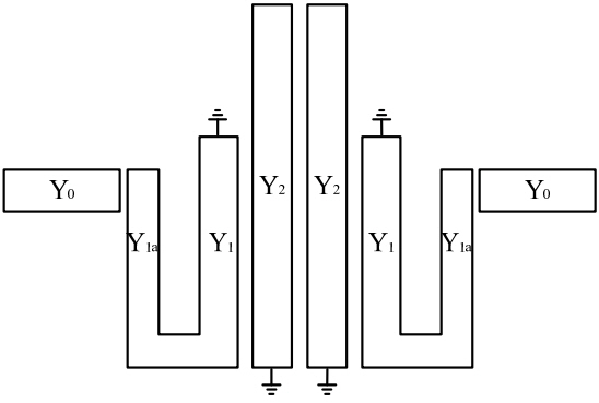
Schematic diagram of the proposed dual-band BPF.
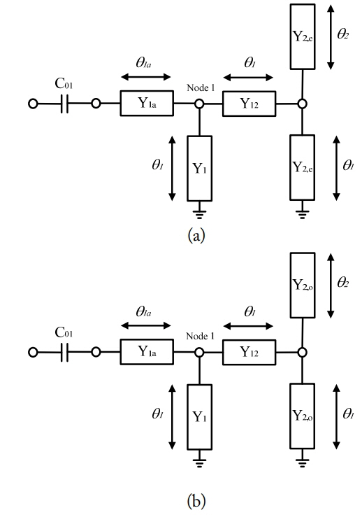
Equivalent circuit of the proposed dual-band BPF: (a) the even mode and (b) the odd mode.
where the subscript i represents e for even-mode and o for odd-mode and Ycpl,i is
or
Ycpl,e is the even-mode input admittance at node 1 as shown in Fig. 2(a), and Ycpl,o is the odd-mode one as shown in Fig. 2(b).
Under the even-mode excitation of Fig. 2(a), the resonance condition can be derived by setting Yin,e = 0. Two even-mode resonant frequencies, fe1 and fe2, are derived by following equations.
Under the odd-mode excitation of Fig. 2(b), two resonant frequencies, fo1 and fo2, can be produced by setting Yin,o = 0 as follows:
The transfer function, S21, can be expressed as
where Y0 is the admittance of the input/output port. A transmission zero is created when S21 = 0, i.e.,
Therefore, a transmission zero is created when
Fig. 3 describes the resonant characteristics of the proposed BPF with weak input/output coupling against the electrical lengths θ1, θ1a, and θ2, respectively. In Fig. 3(a), all resonant frequencies and transmission zero frequency shift down evenly as the electrical length, θ1 increases because θ1 is the electrical length of interdigital coupled lines. Fig. 3(b) shows that the variation of electrical lengths θ1a changes two lower resonant frequencies, while the transmission zero frequency keeps constant. θ2 makes the two upper resonant frequencies and transmission zero frequency shift as shown in Fig. 3(c). From the simulation results, we found out that the central parallel CLs build an upper passband and a transmission zero, and two U-shaped SIRs build a lower passband.
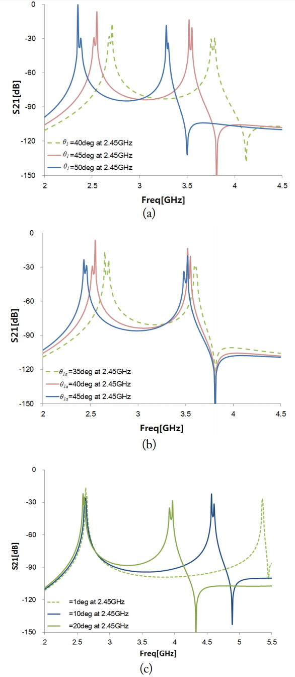
Resonant characteristics of the proposed BPF of weak coupling against the electrical length: (a) θ1 (θ1a = 40o, θ2 = 25o), (b) θ1a (θ1 = 45o, θ2 = 25o), and (c) θ2 (θ1a = 40o, θ1 = 45o).
III. Design and Fabrication
The proposed dual-band BPF was implemented on a Taconic TLX-8 dielectric substrate with a dielectric constant of 2.55, thickness of 0.787 mm, and loss tangent of 0.0012. The fabricated dual-band BPF shown in Fig. 4 comprises shorted SIRs with interdigital and comb-line type parallel coupled structures. To move the notch frequency, we need to change the lengths of central coupled lines, θ1 and θ2. But varying them, two passbands also vary as shown in Fig. 3. In order to put a notch frequency between two passbands for minimizing the variation of the existing passbands, the parasitic coupled lines were adopted between the main coupled lines as shown in Fig. 4. The effect of the parasitic coupled lines is shown in Fig. 5. The longer the length of the parasitic CLs, the lower the notch frequency. Through the design equation from the previous chapter and simulation by ANSYS HFSS, the dimensions for this dual-band BPF were established as follows: w1 =2.2 mm, w2 = 0.5 mm, w3 = 1.0 mm, w4 = 1.2 mm, w5 = 1.25 mm, l1 = 5.9 mm, l2 = 8.0 mm, l3 = 4.22 mm, l4 = 10.0 mm, l5 = 15.0 mm, l6 = 2.38 mm, g1 = 0.13 mm, g2 = 0.35 mm, and g3 = 1.3 mm. The overall size of the filter is 14 × 15 mm2, approximately 0.17λg × 0.18λg, λg being the guided wavelength at the center frequency of the first passband. The measurements were performed using an Anritsu 37347C vector network analyzer. The simulated and measured results of the fabricated filter are shown in Fig. 6, and show good agreement. For the first passband of 2.45 GHz, the insertion loss is less than 1.02 dB. For the second passband of 3.42 GHz, the measured insertion loss is less than 3.01 dB; the band-to-band isolation is more than 40 dB from 3.14–3.2 GHz. The difference of the insertion loss of the simulated and measured results in the second band seems to be caused by the radiation loss and mismatching in the input and output port. Table 1 summarizes the performance comparison of the proposed filter with some previously reported ones. As shown, the fabricated dual-band BPF has higher band-to-band isolation than those proposed in the works under comparison, and its size is more compact than that proposed in [5] and [11].

Photograph of the fabricated dual-band BPF.
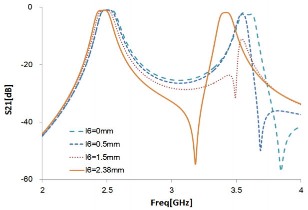
Effect of the parasitic coupled lines.
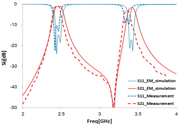
Simulated and measured frequency responses of the dual-band BPF.

Comparison of dual-band BPFs
IV. Conclusion
A dual-band BPF using U-shaped SIRs with PCLs having interdigital and comb-line shorted ends is proposed in this study. The proposed structure is theoretically analyzed to derive its scattering parameters. U-shaped SIRs with PCLs achieve dual-band characteristics. A proposed dual-band BPF was designed and fabricated and good agreement was found between the measured and simulated results. This result validates the design concept. The fabricated filter shows high band-to-band isolation and a compact size.
References
Biography
Gyuje Sung received his B.S., M.S., and Ph.D. degrees in electrical engineering from Sogang University, Seoul, Korea in 1986, 1988, and 1998, respectively. From 1988 to 1993, he worked at Agency for defense Development, Daejeon, Korea. Since 1998, he has been with Hankyong National University, Ansung, Korea, where he is a professor of the Department of Electronic and Electrical Engineering. His research interests include analog circuits, RF and microwave circuits, and antennas.