I. Introduction
A surface dielectric barrier discharge (SDBD) actuator has been examined as a flow controller in aerodynamics [1]. It has several advantages, such as switchable plasma property, absence of mechanical movement, and simple structure, among others. Several efforts have been made to utilize the actuator in flying vehicles. In some studies, SDBD is attached to turbine blades [2, 3], and it presents an outstanding performance in the control of flow separation. Other studies use the actuator to change the air flow around the airfoil [4]. The plasma effect as the change in the angle of flow attack is demonstrated in [5]. At the other end of the spectrum, researchers have attempted to enhance the plasma effect by enlarging the plasma area. Linearly synthesized SDBD has been proposed [6], and it generates a large plasma area. The sliding plasma discharge is examined by designing the electrodes properly [7].
Accordingly, the plasma effects on electromagnetics have gained the interest of researchers because the scattered waves can be influenced by the staggered electrode structures. In addition, the incident waves and plasma may possibly interact. Therefore, the radar cross-section (RCS) of flying vehicles, which is one of the crucial factors for the survival rate of aircrafts, may change. Unexpected effects on RCS may occur because of the SDBD actuators installed for the purpose of controlling flow. To demonstrate the effect on electromagnetic waves, experiments in a certain observation plane have been made [8]. However, various observation planes are required because the SDBD structure has staggered electrodes that can cause reflection and diffraction. Another study analyzes the diffraction based on simulation under low pressure. It reveals that the RCS increases at a specific angle [9]. Experiments under atmospheric pressure are necessary for flying vehicles. The study [10] based on 2D simulation should be extended to 3D to enable analysis in various angles.
The current study focuses on the change in scattering by the SDBD air plasma actuator under atmospheric pressure. Monostatic and bistatic RCS in different observation planes is simulated to demonstrate the effect of a plasma actuator on survivability.
II. Structure of a Plasma Actuator
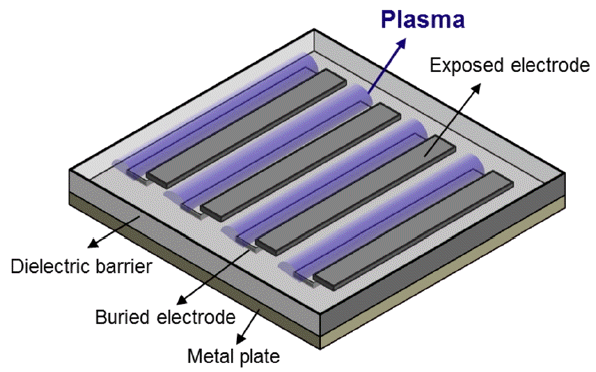
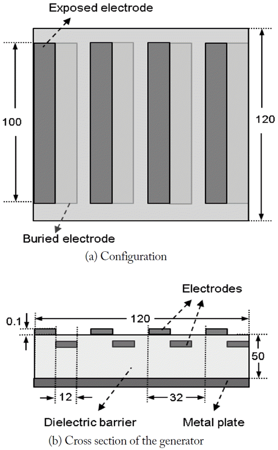
The linearly synthesized SDBD actuator consists of four unit actuators to enhance the plasma effect. The sufficient spacing between the actuators reduces the interference between the adjacent units. Each unit has an exposed and buried electrode with a dielectric barrier. The plasma is generated above the buried electrode (Fig. 1). The plasma actuator is backed by a metal plate to define the surface of the target. The targetis square, with each side measuring 120 mm. The configuration of the designed actuator is illustrated in Fig. 2. The size of the electrode strip is 100 mm Ă 12 mm. The spacing between two units is 8 mm. A substrate with a permittivity of 2.3 is used as the dielectric barrier.
Fig. 3 shows the air plasma generation of the designed actuator. Clearly, the visible plasma is generated on top of the buried electrodes. In addition, the interaction between the unit SDBD actuators is limited. The color of the plasma indicates that the air plasma is generated.
III. Effect on Electromagnetic Waves
1. Diffraction from the Plasma Actuator
The SDBD actuator has a periodic structure, which causes a grating diffraction with the conductor strips acting as a crystal [11]. In Eq. (1), the relation between the incident wave and the diffraction wave is predicted when the grating spacing is determined.
where θd is the diffraction angle, θi is the incident angle, θi is the grating spacing between two elements, and m is the integer number. With the incident angle of 0° and Πof 32 mm, the diffraction angle is calculated as 38.7° when the frequency of the incident wave is 15 GHz. Therefore, the maximum occurs at the angle with the bistatic RCS simulation.
The monostatic RCS can be analyzed as the Bragg diffraction:
The calculation result is 18.2° when m is 1. As a result, monostatic RCS has a maximum diffraction at the angle.
2. Interaction with the Plasma Array
The interaction between cold plasma and incident electromagnetics is determined by dispersion relation,
where Ďp is the plasma frequency, νc is the collision frequency, and Ďc is the operating frequency of the incident wave [12]. Plasma frequency and collision frequency are highly dependent on the plasma generator structure and the ambient pressure and temperature. The collision frequency is a function of the type of gas, neutral gas density, and electron temperature [13]. Measuring all of these variables is difficult. The value of collision frequency is 2.1 THz, which is obtained from the measurement of helium glow discharge under atmospheric pressure [14]. The plasma frequency is calculated from the equation,
where ne is the electron density, e is the electron charge, and m is the mass of the electron. The range of electron density of the DBD actuator is 1017â1021 mâ3 [15]. The electron density largely varies as the structure and the environment change. It is the key to analyzing the interaction between plasma and electromagnetic waves. The electron density and its distribution should be derived. As shown in the following section, plasma modeling for the given actuator provides the electron density distribution.
IV. Plasma Modeling for the Actuator
To derive plasma modeling for the actuator, a simplified modeling for charged particles in plasma is utilized [15]. The relation between the charged particle and the electric potential is defined as Eq. (5).
where ÎŚ is the electric potential in the conductive fluid, and Ďc is the charge density. In Eq. (6), the electric potential can be separated into electric potential due to electrode Ď and electric potential due to charged particles in plasma Ďc. Under the assumption that the Debye thickness is small and the charge on the wall is not large, the potential caused by the electric charge is the dominant factor in the decision of the charge distribution. The effect of the external electric field is relatively small [16]. Then, Eq. (5) can be converted to Eq. (7).
where Ér is the relative permittivity, and Îťd is the Debye thickness. Based on a time-independent system, the density of the charged particle can be expressed as a normalized from
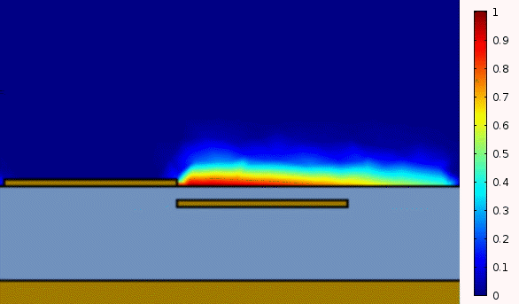
where Ďcmax is the maximum charged particle density and f(t) is the time-dependent factor. On the surface of the dielectric, the charged particle follows a half Gaussian distribution [17]. Then, the electron density can be derived as
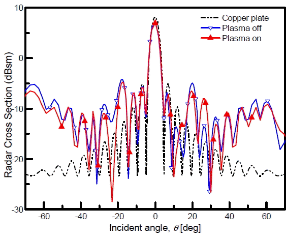
where kB is the Boltzmann constant, and Te is the electron temperature. The calculated normalized electron density is shown in Fig. 4 by using multi-physics software (COMSOL Inc., Palo Alto, CA, USA). The maximum occurs on top of the buried electrode, and the density weakens as the distance from the surface increases. The maximum electron density is set to 1 Ă 1021 mâ3, which corresponds to the electron range in a previous work metric pattern in the y-z plane because of the staggered electrodes in the actuator. Compared with the copper plate, sudden increases occur near â20° and 20° that are caused by the Bragg diffraction, the calculated incident angle of which is 18.2° in the previous section. When the plasma is generated, a decrease of 10°â20° occurs, and a sudden increase is observed in 30°. The reason for this outcome is that the inhomogeneity of the plasma distribution changes the direction of the scattering waves.
V. RCS of the Target
Fig. 5 shows the coordinates for the DBD plasma actuator in the x-y plane. Monostatic and bistatic RCSs are calculated as shown in Figs. 6â9 using COMSOL multi-physics software.
1. Monostatic RCS
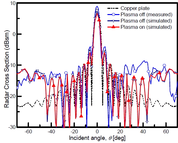
When the linearly polarized electromagnetic wave along the y-axis is incident toward the DBD with a frequency of 15 GHz, the monostatic RCS is observed in the x-z plane as shown in Fig. 6. The copper plate has a prominent peak at 0°. Most of the field hits the plate and reflects back toward it. If the radar is in the different direction, backward reflection will decrease because of specular reflection. For the plasma-off state, the peak around 0° is explained similarly. At a different angle, the incident fields are scattered by the electrodes, which increase the level of monostatic RCS. Accordingly, the RCS for the plasma-off state is higher than that for the copper plate. In addition, the simulated result with the plasma-off is compared with the measured result reported by Wolf and Arjomandi [8]. A good agreement was found in the simulated and measured results in the range of â20° to 20°. The main beam at 0° is observed because of a specular reflection from the copper plate. The experimental result indicated a distorted pattern in 30°â40°. The level of measurement result with the plasma-off state is higher than that of the simulation. This outcome may be due to the undesired effects from background noise. However, the simulated monostatic RCS of DBD and the analytic solution of the square copper plate show symmetry. When the plasma is generated, the graph shows no significant change. The generated plasma may have a minor effect on the monostatic RCS in the Ď = 0° plane.
2. Bistatic RCS
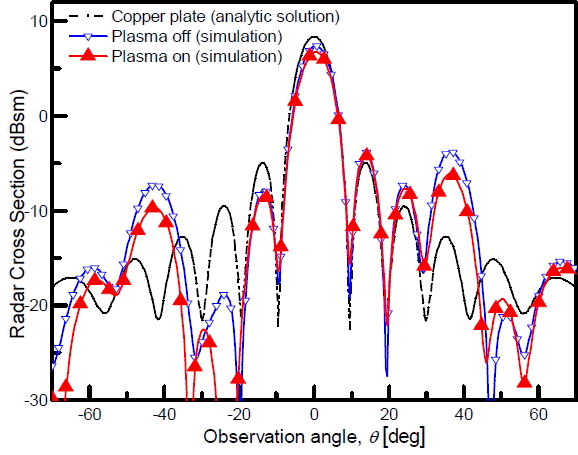
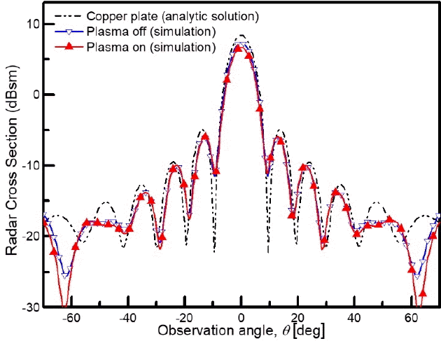
Fig. 8 shows the bistatic RCS when the incident wave is linearly polarized in the x-z plane. The plasma-off state RCS is comparable with that in the case of the square copper plate. A peak at 0° is observed because of the specular reflection. In addition, the plasma effect does not appear in the graph. As shown in Fig. 8, the distortion due to the plasma actuator is notable in Fig. 9. When the incident angle is 0°, the diffraction angle is 38.7°. Two peaks due to diffraction can be observed at the diffraction angles. The peaks are at least 5 dB higher than that in the case of the copper plate. As the plasma is generated, the overall level decreases by 2â3 dB. The RCS near â25° has notable effects. The attenuation by plasma decreases the RCS by 10 dB at the frequency range. It is related to the distribution of plasma, which is periodically located near exposed electrodes. The reduction is caused by both the staggered electrode alignment of the generator and the plasma distribution.
VI. Conclusion
The SDBD plasma has a significant effect on RCS. Peaks by diffraction are observed in both plasma-off and -on states because of the periodicity of staggered electrodes. In the plasma-on state, the inhomogeneous plasma distribution causes both the reduction of the level and the change in scattering angles. These effects become different as the RCS observation plane changes.
If the operating frequency or spacing between electrodes is changed, the location of peaks due to diffraction can be controlled. Therefore, moving the peaks to the unimportant angles is possible, thus reducing the level of RCS in the desired range of angles. However, the changes in the structure affect the process of plasma generation. They lead to different reflections and absorption properties by plasma. Therefore, such relations should be considered in the DBD actuator design. Further research should include the effect of a complex electrode structure on plasma generation.