Design of a Short/Open-Ended Slot Antenna with Capacitive Coupling Feed Strips for Hepta-Band Mobile Application
Article information
Abstract
In this paper, a planar printed hybrid short/open-ended slot antenna with capacitive coupling feed strips is proposed for hepta-band mobile applications. The proposed antenna is comprised of a slotted ground plane on the top plane and two capacitive coupling feed strips with a chip inductor on the bottom plane. At the low frequency band, the short-ended long slot fed by strip 1 generates its half-wavelength resonance mode, whereas the T-shaped open ended slot fed by strip 2 generates its quarter-wavelength resonance mode for the high frequency band. The antenna provides a wide bandwidth covering GSM850/GSM900/DCS/PCS/UMTS/LTE2300/LTE2500 operation bands. Moreover, the antenna occupies a small volume of 15 mm × 50 mm × 1 mm. The operating principle of the proposed antenna and the simulation/measurement results are presented and discussed.
I. Introduction
With the rapid development of mobile communication technology and diversified demand of mobile users, multi-band antennas become essential for mobile communication systems [1]. In some mobile applications, it is desirable to integrate heptaband systems, such as GSM850/GSM900 bands in the lower band and DCS/PCS/UMTS/LTE2300/LTE2500 bands in the upper band, into a single mobile device. However, it is a big challenge for a single mobile device to accommodate a heptaband antenna due to the space limitation of the printed circuit board (PCB). For this reason, a mobile antenna should be designed in low profile planar structure and in compact size without deteriorating the performance. Slot antenna, with the advantages of low-profile, simple structure, and easy integration with other devices, is a good candidate for the design of multi-band antennas [2, 3]. However, the slot antenna has difficulty covering the low-frequency bands by a single resonance [4]. To overcome this problem, various researches using multi-resonance at the lower frequency band have been studied [5–9]. In these studies, multi-resonance characteristic was achieved by using capacitive coupling feed. However, these antennas have narrow bandwidth at high-frequency bands.
In this paper, we propose a compact slot antenna covering GSM850 (824–894 MHz), GSM900 (880–960 MHz), DCS (1,710–1,880 MHz), PCS (1,850–1,990 MHz), UMTS (1,920–2,170 MHz), LTE2300 (2,305–2,400 MHz), and LTE2500 (2,500–2,690 MHz) bands. The proposed antenna consists of two capacitive coupling feed strips, a chip inductor, a short-ended slot, and an inverted T-shaped open-ended slot. The proposed antenna is simulated by ANSYS High-Frequency Structure Simulator (HFSS; ANSYS Inc., Canonsburg, PA, USA).
II. Antenna Design
The configuration of the proposed antenna for hepta-band mobile application is shown in Fig. 1. The antenna is designed on a FR-4 (ɛr = 4.4, tanδ = 0.02) substrate with a thickness of 1 mm. The dimension of FR-4 substrates is 50 mm × 115 mm ×1 mm, and the antenna with a dimension of 15 mm × 50 mm × 1 mm is located at the upper side of the substrate. The short-ended slot forms a loop along the edge of the antenna and the T-shaped slot is placed at the upper edge of the ground plane. Coupling feed strip is comprised of strip 1 and strip 2. The chip inductor is connected in series with the strip 1 and strip 2. The short-ended slot and T-shaped slot, are excited by strip 1 and strip 2, respectively. By electromagnetic coupling between the short-ended slot and strip 1, dual resonances are generated to cover GSM850/900 bands. A wideband characteristic at the high-frequency band is achieved by the combination of the harmonic resonance of the short-ended slot and the resonances due to the T-shaped slot and the strip 2. Table 1 shows the design parameters of the proposed antenna and the fabricated antenna is shown in Fig. 2. Fig. 2(a) shows the slots of the ground plane and the feed cable and Fig. 2(b) shows the strips and chip inductor.
The geometry of the proposed antenna.
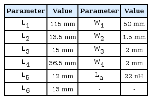
Design parameters of the proposed antenna
Prototyped antenna: (a) top view and (b) bottom view.
III. Antenna Analysis
Fig. 1 shows the various design parameters mostly affecting the antenna performances. In order to analyze and verify the operation principle of the proposed antenna, the parametric study has been conducted.
Fig. 3(a) shows the simulated reflection coefficient when the length of the top slot (L4) varies from 34.5 mm to 38.5 mm. It can be seen that as the length of L4 increases the whole frequency band is shifted to the lower frequency side. In particular, L4 largely affects the reflection coefficient characteristics at GSM900, DCS and LTE bands. These frequencies correspond to the half-wave resonance of the short-ended slot and its second and third harmonic resonances, respectively. The optimal length of L4 is chosen as 36.5 mm. Fig. 3(b) shows the simulated reflection coefficient when the length of the T-shaped slot (L5) changes from 11.5 mm to 12.5 mm. It is observed that the upper frequency band is shifted to lower frequency as the length of L5 increases. In particular, L5 largely affects the performance at GSM900, UMTS, LTE bands. The optimal length of L5, satisfying the −6 dB reflection coefficient is 12 mm. Fig. 3(c) shows the simulated reflection coefficient when the length of the T-shaped slot (L6) is changing from 12 mm to 14 mm. It is shown that as the length of L6 increases, the upper frequency band is shifted to the low frequency side. In particular, the GSM900, UMTS, LTE bands are affected critically by the change of L6. When L6 becomes 14 mm, the antenna has wider −6 dB reflection coefficient bandwidth than that of 13 mm in the high frequency band. However, since the −6 dB reflection coefficient in the GSM and PCS bands is satisfied marginally, the length of L6 is set to 13 mm. Fig. 4 shows the simulated reflection coefficient when the values of the chip inductor La are 18 nH, 22 nH, and 27 nH. The change of the inductor value affects the reflection coefficient characteristic in the lower frequency GSM band more critically than in the upper frequency bands. It can be seen that as the inductor value increases, the resonance occurs at the low side of the lower frequency band, and when the inductor value decreases, the resonance occurs at the high side of the lower band. The −6 dB reflection coefficient at the GSM band is satisfied when the inductor value is 22 nH.
The simulated reflection coefficient with different values of L4 (a), L5 (b), and L6 (c).
Simulated reflection coefficient with different chip inductor values of La.
Fig. 5 shows the surface current distributions on the proposed antenna. At lower bands, the surface current around the short-ended slot is strongly excited by the capacitive coupling due to feed strip 1. This current distribution shows that the short-ended slot with the strip 1 generates the half-wavelength resonance [10, 11] and its harmonic modes at the vicinity of 0.85, 1.73, and 2.50 GHz. At the upper bands, the intensity of the surface current distribution around the T-shaped slot becomes relatively stronger than that at the lower-frequency band. The current distribution shows that the T-shaped open-ended slot with the strip 2 generates the quarter-wavelength resonance mode [10] at the vicinity of 2.06 GHz and 2.50 GHz.
The simulated surface current distributions on the proposed antenna.
IV. Simulation and Measurement Results
Fig. 6 shows the simulated and measured reflection coefficients of the proposed antenna. The −6 dB reflection coefficient bandwidths are 260 MHz (0.77–1.03 GHz) at the lower band and 1,040 MHz (1.66–2.70 GHz) at the upper band. The bandwidth of the proposed antenna is wide enough to cover the desired hepta-band. The measured 2D radiation patterns of the proposed antenna are shown in Fig. 7. The 2D radiation patterns were measured at the center frequency of each band. At low frequencies, with the center frequencies of the GSM850 and GSM900 bands at 0.86 GHz and 0.92 GHz, respectively, dipole-like radiation patterns can be observed in the x-z plane. In the x-y plane, the radiation patterns are omni-directional. At high frequencies, with the center frequencies of the DCS, PCS, UMTS, LTE2300, and LTE2500 bands at 1.80, 1.92, 2.05, 2.35, and 2.60 GHz, respectively, the proposed antenna has quasi-omnidirectional radiation patterns. Fig. 8 illustrates the simulated and measured efficiencies and maximum gains of the proposed antenna. The measured efficiencies and maximum gains are 51.8% and 0.93 dBi, 54.6% and 0.8 dBi, 49.5% and 2.26 dBi, 62.7% and 3.02 dBi, 71.1% and 2.24 dBi, at 0.85, 0.98, 1.73, 2.06, and 2.50 GHz, respectively. As shown in Fig. 8, the measured efficiencies and maximum gains are substantially lower than the simulated results. This is mainly due to the metal surface roughness of the FR4 substrate which is not accounted for in the simulation [12]. Moreover, the percent error of the chip inductor and fabrication errors of capacitive coupling strips lead to the loss of gain.
Simulated and measured reflection coefficient of the proposed antenna.
Simulated and measured radiation patterns of the proposed antenna at (a) 0.86 GHz, (b) 0.92 GHz, (c) 1.80 GHz, (d) 1.92 GHz, (e) 2.05 GHz, (f) 2.35 GHz, and (g) 2.60 GHz.

Simulated and measured efficiencies and maximum gains of the proposed antenna.
V. Conclusion
In this paper, a hepta-band planar printed hybrid short/open-ended slot antenna with capacitive coupling feed strips is proposed. By properly choosing the lengths of feed strip 1 and strip 2 and the value of chip inductor, the proposed antenna has a wide bandwidth of 260 MHz covering GSM850 and GSM900 bands in the lower frequency band and 1,040 MHz covering DCS, PCS, UMTS, LTE2300, and LTE2500 bands in the upper frequency band. The geometrical parameters of the short-ended slot and the feeding strip 1 are mainly affecting the antenna performances at GSM900, DCS, and LTE bands and those of open-ended T-shaped slot and the feeding strip 2 determines the antenna characteristics at GSM900, UMTS, and LTE bands. Along with the wide bandwidth, the antenna has good radiation properties desired for mobile communication applications.
Acknowledgments
This work was supported by the National Research Foundation of Korea (NRF) grant funded by the Korea government (MSIP) (No. 2017R1A2B4002811).
References
Biography

Kyoseung Keum received his B.S. in Information and Communication Engineering from Soonchunhyang University in Asan, Korea, in 2015. He is currently working toward a combined master’s and Ph.D. degree in the Department of Electronics and Computer Engineering at Hanyang University in Seoul, Korea. His research interest focuses on various antenna designs, mainly compact multi-band antennas for mobile wireless communication applications.

Jaehoon Choi received his B.S. from Hanyang University in Korea, and his M.S. and Ph.D. degrees from Ohio State University in Ohio in 1980, 1986, and 1989, respectively. From 1989 to 1991, he served as a research analyst at the Telecommunication Research Center at Arizona State University in Tempe, Arizona. He worked for Korea Telecom as a team leader of the Satellite Communication Division from 1991 to 1995. Since 1995, he has been a professor in the Department of Electronics and Computer Engineering at Hanyang University in Korea. He has published more than 250 refereed journal articles and numerous conference proceedings. He also holds over 80 patents. His research interests include antennas, microwave circuit design, and electromagnetic compatibility. Currently, his research is mainly focused on the design of compact multiband antennas for mobile wireless communication and antennas for biomedical applications.

Haiyan Piao received her B.S. in telecommunication engineering from Yanbian University in Yanji, China, in 2013. From 2013 to 2015, she served as an information technology researcher at China Telecom. She is currently working toward a master’s degree in the Department of Electronics and Computer Engineering at Hanyang University in Seoul, Korea. Her research interest focuses on various antenna designs, mainly compact multi-band antennas for mobile wireless communication applications.