 |
 |
- Search
| J. Electromagn. Eng. Sci > Volume 17(4); 2017 > Article |
|
Abstract
In this paper, a dual-band high frequency (HF) and ultra-high frequency (UHF) radio-frequency identification (RFID) tag antenna is presented that operates in the 13.56 MHz band as well as in the 920 MHz band. A spiral coil along the edges of the antenna substrate is designed to handle the HF band, and a novel meander open complementary split ring resonator (MOCSRR) dipole antenna is utilized to generate the UHF band. The dual-band antenna is supported by a single-feeding port for mono-chip RFID applications. The antenna is fabricated using an FR4 substrate to verify theoretical and simulation designs, and it has compact dimensions of 80 mm ├Ś 40 mm ├Ś 0.8 mm. The proposed antenna also has an omnidirectional characteristic with a gain of approximately 1 dBi.
Radio-frequency identification (RFID) is an emerging technology and is one of the most rapidly growing segments of todayŌĆÖs automatic identification and data collection industry [1]. High frequency (HF) and ultra-high frequency (UHF) bands have many advantages over other bands that are frequently used in RFID. In terms of operating frequency bands, HF bands are widely applied in short-distance reading applications because they provide improved security and greater information storage capability because of their near-field operation. UHF bands offer better speed and are often applied in long-distance reading applications [2]. In some special cases, such as logistics, inventtory management and bioengineering, both short- and long-distance reading are needed. Therefore, a single RFID antenna with a dual operating frequency band is required. Combining both RFID standards on the same tag would increase this antennaŌĆÖs capabilities and could lead to new applications. However, the use of two chips for two bands would increase the cost of the tag. In this paper, a single-feeding port for an application specific integrated circuit (ASIC) mono-chip is used for the dual-band RFID tag antenna.
Prior research on HF-UHF dual-band antennas has already been published [3ŌĆō6]. Typically, the spiral coil is used for the HF antenna to operate at 13.56 MHz. UHF bands vary widely because of the frequency allocations of different countries. In Korea, based on the Korea Communications Commission, UHF bands from 917 MHz to 923.5 MHz are used [7]. A meander-line dipole is often used to generate the UHF antenna placed inside or outside of the HF coil. However, the current on the vertical conductor of each dipole arm is in the opposite direction to the current on each adjacent vertical conductor. This results in a far field that is canceled by these elements. Thus, the radiation from the meander-line dipole is mainly due to the small horizontal segments connecting each vertical segment [8]. In [8], a meander open complementary split ring resonator (MOCSRR) particle was presented to overcome the restrictions of the conventional meander-line dipole. In this paper, a novel MOCSRR structure is presented to handle UHF bands.
This paper is organized as follows. The antennaŌĆÖs structure and dimensions are introduced in Section II. In Section III, the design methodology and results are given from the analysis of HF and UHF parts, respectively. The fabrication and measurement results of the dual-band antenna are presented in Section IV.
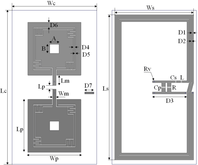
The proposed antenna structure is shown in Fig. 1. The HF and UHF antennas are placed on two sides of the FR4 (╔ø = 4.4, tan╬┤ = 0.02) substrate with 1.2 mm thickness and the following dimensions: Wc = 45 mm, and Lc = 82 mm. The proposed antenna has a single-feeding port for mono-chip HF-UHF bands that are connected by via with radius of Rv = 0.2 mm. The dimensions of the feeding port are as follows: Wm = 1.8 mm, Lm = 5.4 mm, and Lp = 2 mm. The HF antenna is a three-turn spiral coil with Ws = 42.2 mm, Ls = 77.2 mm, D1 = 1 mm, D2 = 0.3 mm, D3 = 17.5 mm, and D7 = 4.9 mm. The MOCSRR dipole UHF antenna structure parameters are Wp = Ls = 28.2 mm, D4 = 0.7 mm, D5 = 0.3 mm, D6 = 2.8 mm, and A = B = 4.9 mm. It should be noted that the UHF antenna has a diagonal symmetric structure. Two rectangular slots in the two arms are used to fine-tune the impedance. The dual-band RFID antenna was designed to match the ASIC chip impedance, which has a standard impedance of 50 ╬®. The chip was self-designed to match the standard impedance at the operating dual-band frequency. The design was simulated and optimized in ANSYS HFSS software (ANSYS Inc., Canonsburg, PA, USA). A two-solution frequency at HF and UHF bands was applied in the simulation software to obtain the wide-band results from HF to UHF frequencies.
The basic process of designing a dual-frequency antenna is to create an HF and a UHF antenna separately and then join these two antennas together with a single feeding-port. However, since these two antennas are joined together in parallel, the UHF antenna will affect the HF antennaŌĆÖs operation and vice versa. In the proposed antenna, the HF and UHF antennas are placed on either side of the substrate to minimize the mutual interaction and decoupling issues between the HF and UHF antennas.
For the design of the HF band antenna, a printed three-turn spiral coil is used. It is important that the HF antenna coil is placed at the outermost region of the available space in order to collect more magnetic flux. For a combined HF and UHF chip with a single port, a series capacitor that is tuned to the desired resonant frequency presents a short circuit at the chip input for UHF and thus inhibits operation [9]. In this paper, a set of RLC components is used to tune the resonant frequency of 13.56 MHz and reduce the resistive losses in the antenna coil as shown in Fig. 1.
Various antenna types are used for UHF band operating frequencies, such as patch, slot, and meander-line antennas. The planar meander-line antenna is the most useful because of its advantages of size reduction and simple configuration. However, the radiation from the meander-line dipole is restricted because of the opposite direction of the current in each adjacent vertical conductor. The MOCSRR particle was presented to improve upon the conventional meander-line dipole in [8]. In this paper, a novel and modified MOCSRR structure is used to generate a UHF operating frequency fed with a 50-╬® microstrip feeding line, as shown in Fig. 1.
After completing the designs of the HF and UHF band antennas separately, the combined HF and UHF band antenna is implemented to become a single antenna with a single-feeding port. However, the HF and UHF band antennas affect each other, which is conducive to change of the antenna characteristics. Therefore, the dual-band antenna is tuned and modified to obtain the desired operation of both frequency bands.
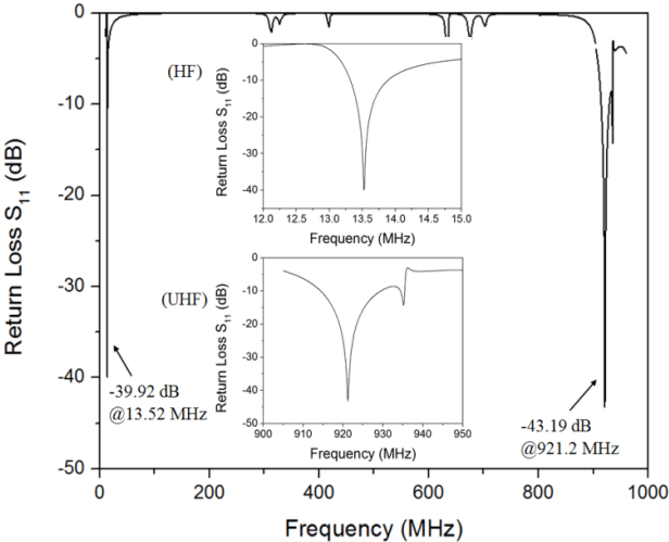
The simulation results of the return loss S11 parameters for the dual-band antenna are shown in Fig. 2. The resonant frequency of the HF band antenna is 13.52 MHz with a low return loss of ŌłÆ39.92 dB, whereas the resonant frequency of the UHF band antenna is 921.2 MHz with a ŌłÆ43.19 dB return loss. It is obvious that the dual-band antenna is a good match for the feeding port impedance. The details of each band frequency are plotted by two inset figures for the HF and UHF bands, respectively. The ŌłÆ10 dB bandwidth of the UHF band covers 914.3 MHz to 929.5 MHz, which includes the expected frequency range. The simulated radiation pattern and the antenna gain of the dual-band antenna at 921 MHz are illustrated in Fig. 3. The gain of the proposed antenna is around 2 dBi. It presents an omnidirectional characteristic of the antenna at the ŽĢ = 90┬░ plane.
From the analysis and design of the above sections, the proposed antenna was fabricated and measured to verify its performance, as shown in Fig. 4. The dual-band antenna is printed on a 1.2-mm thick FR4 substrate, and the overall size is 82 mm ├Ś 45 mm. A coaxial cable is connected to the single-port dual-band antenna. For a dipole antenna to operate properly, the currents on both arms of the dipole should be equal in magnitude. Ideally, the current along the dipole arm that is connected to the outer conductor of the coaxial cable should be equal to the current on the other dipole arm [10]. However, some of the current may travel down the outside of the outer coaxial cable, leading to an unequal current magnitude between the two arms of the dipole. In addition, because of several factors including the fabrication tolerance, losses that occur during the measurement process and upon exposure to the environment, and the mismatch between the feeding line and the antenna in actual fabrication, the dual-band frequencies shift and differ from the simulation results. As a consequence, optimization is required to ensure that the measurement results obtain the expected dual-band frequency bands.
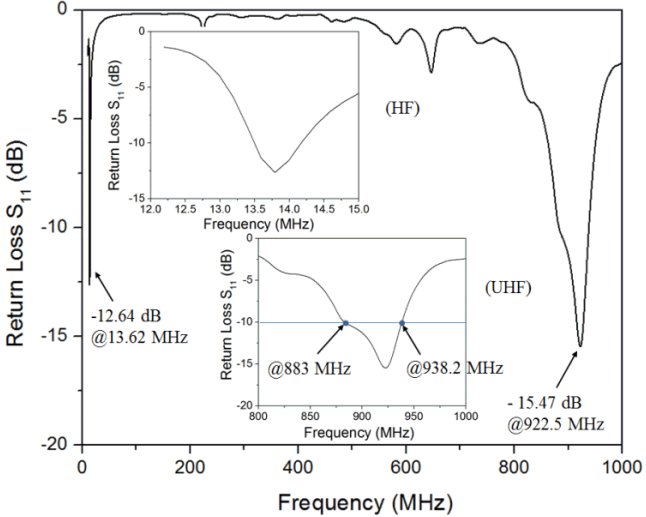
The coaxial cable of the dual-band antenna was connected to a Protek A333 Network Analyzer to measure the return loss. The measured S11 parameters of the dual-band antenna are shown in Fig. 5. The resonant frequencies in the measurement results are slightly different from the ones in the simulation results, with an HF frequency of 13.62 MHz and a UHF frequency of 922.5 MHz, respectively. Although the return losses are also higher, they are acceptable for values lower than ŌłÆ10 dB.
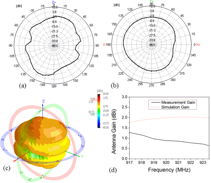
The ŌłÆ10 dB bandwidth for the UHF band frequency covers 883 MHz to 938.2 MHz, which is larger than the bandwidth in the simulation. Fig. 6 presents the measured radiation pattern and gain of the dual-band antenna at 922 MHz. There is good agreement between the simulation and measurement results of the radiation pattern. In the Phi = 90┬░ plane, the dual-band antenna also presents an omnidirectional characteristic that is clearly illustrated in the 3D view of the measured radiation pattern, as shown in Fig. 6(c). A comparison of antenna gain between the simulation and measurement results in a UHF frequency range from 917 MHz to 923.5 MHz is shown in Fig. 6(d). This UHF frequency range is the one used in Korea based on the Korea Communications Commission. The gain in measurement is slightly lower than the gain in simulation because of the losses during the measurement process. A comparison of important factors, such as overall size, the number of ports, the substrates used, and the number of turns, between the proposed antenna and those of related works is presented in Table 1. From this Table 1, it can be seen that the proposed antenna size is significantly compact compared with the other RFID antennas referenced. An FR4 substrate was used, which can reduce the cost of antenna fabrication.
In this paper, a dual-band antenna with HF and UHF band frequencies has been presented. The HF antenna at 13.62 MHz was designed by a three-turn spiral coil, and a novel MOCSRR dipole structure was used to handle the UHF band from 917 MHz to 923.5 MHz. The proposed antenna has a compact size of 82 mm ├Ś 45 mm and is printed to both sides of an FR4 substrate with a thickness of 1.2 mm. In addition, the dual-band antenna presents an omnidirectional characteristic at the UHF frequency and the gain is approximately 1 dBi in the desired UHF frequency range.
ACKNOWLEDGEMENTS
This work was supported by the National Research Foundation of Korea (NRF) grant, which is funded by the Korean Government (MSIP) (No. NRF-2017R1A5A1015596).
Fig.┬Ā3
Simulated radiation pattern in (a) a 2D view and (b) a 3D view and the antenna gain at 921 MHz.
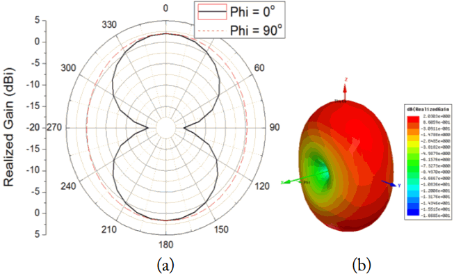
Fig.┬Ā4
Photograph of the manufactured antenna. (a) Top view, (b) bottom view, and (c) measurement configuration of the proposed antenna.
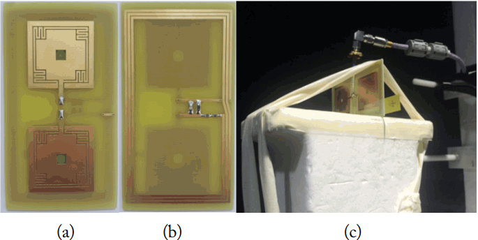
Fig.┬Ā6
Measured radiation pattern in a 2D view: (a) Phi = 0┬░ and (b) Phi = 90┬░. (c) A 3D view of the measured radiation pattern at 922 MHz. (d) simulation and measurement results in a UHF frequency range from 917 MHz to 923.5 MHz.
Table┬Ā1
A comparison of the proposed RFID antenna with those of related works
| Ref. | Substrate | Overall size (mm) | Number of ports |
|---|---|---|---|
| [2] | h = 0.7 mm, ╔ør = 2.2 | 83 ├Ś 49 | Two ports |
| [3] | Roger 4003C, ╔ør = 3.38 | 102.8 ├Ś 64.5 | One port |
| [5] | h = 0.7 mm, ╔ør = 2.2, tan╬┤ = 0.02 | 84 ├Ś 54 | One port |
| [9] | Copper-plated polyimide substrate | 71 ├Ś 46 | One port |
| [11] | FR4, ╔ør = 2.2 | 110 ├Ś 100 | One port |
| This work | FR4, ╔ør = 4.4 | 82 ├Ś 45 | One port |
REFERENCES
1. H Lehpamer, RFID Design Principles. Norwood, MA: Artech House Inc, 2008.
2. P Iliev, P Le Thuc, C Luxey, and R Staraj, "Dual-band HF-UHF RFID tag antenna," Electronics Letters, vol. 45, no. 9, pp. 439ŌĆō441, 2009.

3. CL Tan and W Ismail, "Compact dual band tag antenna design for radio frequency identification (RFID) application," Progress in Electromagnetics Research C, vol. 31, pp. 29ŌĆō40, 2012.

4. ZL Ma, LJ Jiang, and TT Ye, "A single-layer compact HF-UHF dual-band RFID tag antenna," IEEE Antennas and Wireless Propagation Letters, vol. 11, pp. 1257ŌĆō1260, 2012.

5. T Deleruyelle, P Pannier, M Egels, and E Bergeret, "Dual band mono-chip HF-UHF tag antenna," In: Proceedings of the IEEE Antennas and Propagation Society Inter-national Symposium; Toronto, Canada. 2010;pp 1ŌĆō4.

6. M Alibakhshi-Kenari, M Naser-Moghadasi, RA Sadeghzadeh, BS Virdee, and E Limiti, "Dual-band RFID tag antenna based on the Hilbert-curve fractal for HF and UHF applications," IET Circuits, Devices & Systems, vol. 10, no. 2, pp. 140ŌĆō146, 2016.

7. ZN Chen, X Qing, and HL Chung, "A universal UHF RFID reader antenna," IEEE Transactions on Microwave Theory and Techniques, vol. 57, no. 5, pp. 1275ŌĆō1282, 2009.

8. BD Braaten and MA Aziz, "Using meander open complementary split ring resonator (MOCSRR) particles to design a compact UHF RFID tag antenna," IEEE Antennas and Wireless Propagation Letters, vol. 9, pp. 1037ŌĆō1040, 2010.

9. LW Mayer and AL Scholtz, "A dual-band HF/UHF antenna for RFID tags," In: Proceeding of IEEE 68th Vehicular Technology Conference; Calgary, AB. 2008;pp 1ŌĆō5.

11. KS Leong, ML Ng, and PH Cole, "Dual-frequency antenna design for RFID application," In: Proceedings of the International Technical Conference on Circuits/Systems, Computers and Communications (ITC-CSCC); Chiang Mai, Thailand. 2006;pp 29ŌĆō32.
Biography

Nam Ha-Van
received a B.S. degree in electronics and telecommunications from Hanoi University of Science and Technology, Hanoi, Vietnam, in 2012. He is currently working toward an integrated M.S./Ph.D. degree in the department of information communication, materials, and chemistry convergence technology at Soongsil University, Seoul, Korea. His current research interests include wireless power transfer, metamaterials, RFID antennas, phased array antennas, and power amplifiers.
Biography

Chulhun Seo
received B.S., M.S., and Ph.D. degrees in the department of electronics engineering from Seoul National University, Seoul, Korea, in 1983, 1985, and 1993, respectively. From 1993 to 1995, he was a technical staff member with the Massachusetts Institute of Technology (MIT), Cambridge, MA, USA. From 1993 to 1997, he was an Assistant Professor at Soongsil University, Seoul, Korea. From 1999 to 2001, he was a Visiting Professor with MIT. From 1997 to 2004, he was an Associate Professor with Soongsil University, where he has been a Professor of electronic engineering since 2014. Currently, he is the Dean of the Information and Telecommunications College, at Soongsil University. He is also the Director of the Wireless Power Transfer Research Center, which is supported by basic research laboratories through the National Research Foundation grant funded by the Ministry of Science, ICT and Future Planning. His research interests include wireless communication technologies, radio frequency power amplifiers, and wireless power transfer using metamaterials. Dr. Seo was the IEEE MTT Korea Chapter Chairman from 2011 to 2014. He is the President of the Korean Institute of Electromagnetic Engineering and Science.
- TOOLS
- Related articles in JEES
-
Single-Feed Composite Cavity-Backed Four-Arm Curl Antenna2014 ;14(4)


