AoA-Based Local Positioning System Using a Time-Modulated Array
Article information
Abstract
In this paper, we propose an angle-of-arrival (AoA)-based local positioning system using a time-modulated array (TMA). The proposed system can determine a two-dimensional position using only two TMAs without any synchronization between the two receivers. The hardware for the proposed system consists of two commercial monopole antennas, a self-designed switch, and a well-known software-defined radio receiver. Furthermore, the location can be simply estimated in real time without the need for complicated positioning algorithms such as the MUSIC and ESPRIT algorithms. In order to evaluate the performance of our system, we estimated the position of the wireless node in an office environment. The position was estimated with a mean error of less than 0.1 m. We therefore believe that our system is appropriate for various wireless local positioning applications.
I. Introduction
Wireless local positioning is an important issue in various fields, including navigation, tracking, healthcare, security, and ecommerce [1]. In order to address the limitations of Global Navigation Satellite System (GNSS) receivers, for example, the global positioning system (GPS) and Galileo, in indoor and dense urban environments, network-based wireless local positioning systems using multiple reference nodes have been developed. Examples of these systems include the angle-of-arrival (AoA), time-of-arrival (ToA), and time difference-of-arrival (TDoA) systems. AoA-based techniques can estimate the position using only two reference nodes, while the ToA and TDoA techniques require at least three reference nodes [2]. Furthermore, AoA-based positioning does not require synchronization between the reference nodes. For these reasons, an AoA-based positioning system can be considered a practical approach in real applications [3].
However, AoA-based techniques do have certain limitations. To determine the exact angle of direction, the system requires highly directional antennas or antenna arrays, which increase the cost of the AoA system’s implementation [4]. Additionally, complex AoA estimation algorithms, for example, Multiple Signal Classification (MUSIC) and the Estimation of Signal Parameters via Rotational Invariance Technique (ESPRIT), require multiple receivers as well as phase calibration between those receivers. Systems that use multiple receivers usually consume more power and prove expensive to implement. From a hardware perspective, an AoA system with a single receiver is hence cheaper and more practical [5].
Fortunately, [6] showed that a direction finding system could be implemented easily using a time-modulated array (TMA) with a single receiver. Based on this idea, we successfully implemented a real-time direction finding system using a TMA and the LabVIEW program on a commercial software-defined radio receiver [7].
In this paper, expanding this idea to the field of local positioning, we present a simple AoA-based local positioning system using TMAs. Our system can determine the two-dimensional (2D) location using only two TMAs without synchronization between the two receivers. Naturally, our system can estimate the AoA in real time without the need for a complicated algorithm. To the best of our knowledge, this is the first successful implementation of a local positioning system using TMAs.
II. Time-Modulated Array
Fig. 1 shows a TMA receiver for direction finding. Each antenna receives the signal of a target by turning the single-pole double-throw (SPDT) switch on/off. The SPDT switch itself is controlled by a square wave using a function generator, and its duty cycle is 50%.
TMA receiver for direction finding.
When two antennas receive a signal with the spacing ‘D’, the harmonic components are produced at the output spectrum via the switching frequency. The fundamental and first harmonic values are used to calculate the direction of the signal source, as shown in Eq. (1) [6].
α0 and α1 are the powers of the fundamental and first harmonic components, respectively. K is the wavenumber, which is equal to 2πFc/c. Fc is the center frequency of the signal source, while c is the speed of light in the vacuum. We conducted a simple test to verify the performance of the TMA receiver. The TMA receiver was fixed to a desk and a target was placed 1 m away from the receiver. The signal of the target was a continuous wave (CW) with a center frequency of 2.4 GHz. The power spectrum for the signals received from different directions (0°, 10°, 20°, and 30°) is shown in Fig. 2. When the switching frequency was set to 2 kHz, the harmonic components appeared at intervals of 2 kHz from the center frequency. In Fig. 2, the fundamental and first harmonic components are indicated as a blue line and a red dashed line, respectively. As can be seen in Fig. 2, the difference between the fundamental and first harmonic components varies for the different directions. The power of the fundamental and first harmonic components was used to calculate the angle with Eq. (1).
Power spectrum of four different directions (Δα=α0−α1).
III. Local Positioning System
The simple AoA-based local positioning system using only two TMA receivers is presented in Fig. 3. To identify the position of the signal source, we had to set the coordinates of the positions of the two different TMA receivers as (x1,y1) and (x2,y2). At each TMA receiver, the measured AoA also needs to determine the position of the signal source. The TMA receivers 1 and 2 respectively estimate the angles θ1 and θ2 via the TMA direction found through Eq. (1).
Diagram of a local positioning system based on the AoA.
The coordinates of the signal source’s position can be calculated using Eq. (2) and Eq. (3).
IV. Local Positioning Based on the AoA Using TMAs
In this paper, we present a simple AoA-based local positioning system using TMAs, as shown in Fig. 4. Each output of the TMA receivers is connected to the universal software radio peripheral (USRP), while the control unit controls the operation of the SPDT switch. The received signal in the USRP is shifted to the baseband frequency by a down converter. In order to configure multiple devices using a single Ethernet interface, we connected the USRP 1 and USRP 2 using a MIMO (multiple input multiple output) cable. Using the LabVIEW program on the host PC, the AoA from each TMA receiver as well as the coordinates of the target can be calculated. This provides a simple means of identifying the position of a target without the need for complicated positioning algorithms such as the MUSIC and ESPRIT algorithms.
AoA-based local positioning system using TMAs.
V. Experimental Results
Fig. 5 shows the experimental set-up for our proposed simple AoA-based local positioning system using TMAs in a 1 m × 2 m typical office environment. We used a CW signal as the signal source with a commercial monopole antenna (Fig. 5(a)) connected to the signal generator (Fig. 5(d)). The center frequency of the signal source was 2.4 GHz, while the amplitude was 10 dBm. The spacing ‘D’ between the antenna elements in each TMA receiver was about 6 cm. We fixed the two TMA receivers (Fig. 5(e) and (h)) to the edge of the desk, and the heights of Fig. 5(a), (e), and (h) were approximately 75 cm. A power supply (Fig. 5(c)) was used to provide the necessary power, and the function generator was connected to the SPDT switch of each TMA receiver as a control unit (Fig. 5(b)).
Experimental set-up of the proposed system.
A square wave (high level = 3.3 V; low level = 0 V) was generated as a control signal and its switching frequency was set to 2 kHz. Each USRP (Fig. 5(f)) received the output of the TMA receiver, which was transmitted to the LabVIEW program (Fig. 5(g)) for the positioning of the target.
We measured 16 points in a 1 m × 2 m office environment. The 2D position estimation results of the proposed system are shown in Fig. 6. The blue circle indicates the real position, while the red-cross indicates the estimated position of the target.
The 2D positioning estimation of the proposed system.
In Table 1, the distance between the real position and the estimated position is calculated for each positioning error. A maximum positioning error of 0.178 m is indicated at the position (0.2 m, 1.6 m), while a minimum positioning error zero is indicated at the position (0.6 m, 0.8 m). The average positioning error is 0.079 m in a typical office environment.
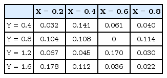
The positioning error at 16 points (unit: m)
The positioning error might have occurred for a number of reasons, including the mutual coupling between the two antennas in a TMA receiver and the influence of the reflected wave in a typical office environment characterized by obstacles.
VI. Conclusion
In this paper, we suggested a simple AoA-based local positioning system using TMAs. It represents a new attempt at implementing a local positioning system with TMAs. Due to the use of TMAs, large antenna arrays are not needed to identify the direction. Our system offers the advantage of simple hardware and algorithm composition. The performance of the proposed system was demonstrated through an experiment, and the results indicated an average positioning error of 0.079 m in a 1 m × 2 m typical office environment. We intend to conduct more studies on local positioning in the future using multiple devices in a more spacious office environment.
Acknowledgements
This work was supported by Institute for Information & communications Technology Promotion (IITP) grant funded by the Korea government (MSIT) (No. 2016-0-00080, Germanium on silicon based sensor which covers visible spectrum to short wavelength infra-red range (400–1600 nm) for materials identification and application system development).
References
Biography

Kyung-Jin Baik
received her B.S. degree in Electrical Engineering from Kookmin University, Seoul, Korea, in 2017. She is currently working toward her M.S. degree in the Department of Electrical Engineering, Kookmin University. Her current research interests concern local positioning, radar signal processing, motion recognition, and machine learning.

Sangjoon Lee
received his B.S. degree in Electrical Engineering from Kookmin University, Seoul, Korea, in 2017. He is currently working toward his M.S. degree in the Department of Electrical Engineering, Kookmin University. His current research interests are in the fields of local positioning, radar signal processing, frequency interference modeling and spectrum engineering, and software-defined radio.

Byung-Jun Jang
received his B.S., M.S., and Ph.D. degrees in electronic engineering from Yonsei University, Seoul, Korea, in 1990, 1992, and 1997, respectively. From 1995 to 1999, he worked for LG Electronics in Seoul, where he developed code-division multiple access and digitally enhanced cordless telecommunication RF modules. From 1999 to 2005, he was with the Electronics and Telecommunications Research Institute, Daejeon, Korea, where he performed research in the fields of satellite RF components and monolithic microwave integrated circuits. In 2005, he joined Kookmin University, Seoul, where he currently works in the Department of Electrical Engineering. His current research interests include RF circuit design, radio-frequency identification system design, wireless power transfer system design, frequency interference modeling and spectrum engineering, and wireless sensor design.