Analysis of Radar Cross Section of a Battleship Equipped with an Integrated Mast Module Based on PO and PTD
Article information
Abstract
In this paper, we analyze the radar cross section (RCS) of a battleship equipped with an integrated mast module (IMM). The RCS of a battleship equipped with an IMM is calculated based on physical optics (PO) and the physical theory of diffraction (PTD), and is analyzed in terms of the mast shape, incident angles, and polarization.
I. Introduction
Stealth technology for battleships reduces the likelihood of enemy radar detection by reducing the radar cross section (RCS). The state-of-the-art stealth destroyer ‘Zoom Walt’ is stealth-capable enough to appear on radar as a small fishing boat. For this extreme stealth-oriented design, an integrated mast module (IMM) system must be developed. An IMM system radically reduces the RCS by integrating the ship’s radar systems, which increase the RCS on the shipboard. The shape of the mast has the greatest impact on the RCS of an IMM [1]. Since the shape of the mast is taken into account in the early stage of ship design, it is necessary to know the characteristics of the RCS of the battleship according to the shape of the mast. The RCS of IMMs has been studied based on physical optics (PO) and the physical theory of diffraction (PTD) [2]. However, no study on the RCS of an IMM-equipped battleship has been presented.
In this paper, we use PO and PTD to calculate the RCS of a battleship equipped with an IMM. We analyze the RCS in terms of the mast shape, incident angles, and polarization.
II. Analysis Method of RCS
Physical optics and PTD are most often used to calculate the RCS of large scatterers such as battleships [3–5]. We calculate scattered fields from planes using PO and diffracted fields from edges using PTD. We also consider the second reflection fields to improve the accuracy of the computation. Fig. 1 shows the problem geometry of an IMM-equipped battleship. The shape of the IMM is changed by reducing the size of its upper surface and the dimension are shown in Table 1. We calculate the RCS of the battleship using a program developed in our previous study [2].
III. Computation Results
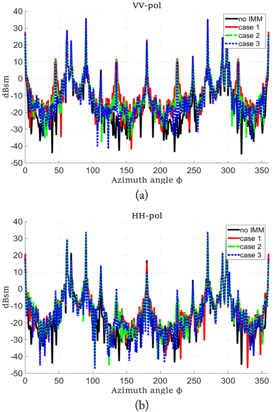
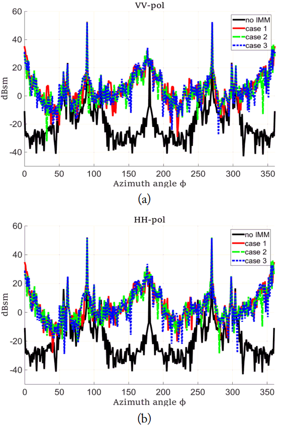
Since the enemy radar is usually far from the battleship, we calculate the RCS of the battleship at S-band for elevation angles θ = 0°, 3° and 5° in Figs. 2–4, respectively. We consider the VV and HH polarizations. Note that the RCS increases significantly due to the IMM in all three cases compared to the case without an IMM. This demonstrates that the shape of the IMM is crucial to the stealth function of battleships. The RCS decreases for all elevation angles and all polarizations as the upper size of the IMM decreases, reducing the slope of the IMM. The geometric means of the RCS are known to effectively represent the changes in the RCS for all azimuth angles [1]. Table 2 shows the geometric means of the RCS for all cases. It can be seen that the geometric mean decreases as the size of the upper surface of the mast decreases at the same elevation angle. As the elevation angle increases, the geometric mean of the RCS increases for all cases equipped with an IMM because the second reflections increase due to the increase in reflections between the deck and the IMM. Note that the RCS of the IMM-equipped ship increases by 30 dBsm and the size of the IMM is about 48λ × 48λ [6]. Therefore, it can be seen that changing the shape of an IMM can reduce the RCS of the battleship equipped with an IMM. We need to study the impact of the ocean surface on RCS in future studies since we have not considered the effect of the ocean surface.
IV. Conclusion
We have calculated the RCS of a battleship equipped with an IMM based on PO and PTD. The RCS has been analyzed in terms of the mast shape, incident angle, and polarization. We also showed that changing the shape of the IMM can reduce the RCS. The results can be used to develop an IMM-equipped battleship with stealth capabilities.
Acknowledgements
This research was partly supported by Hanwha systems and Basic Science Research Program through the National Research Foundation of Korea (NRF) funded by the Ministry of Science and ICT (No. 2017R1A2B4001903).


