Theoretical and Experimental Investigation of N-Bit Reconfigurable Retrodirective Metasurface
Article information

Abstract
The PIN diode-based N-bit reconfigurable retrodirective metasurface (N-bit RRDM) is a next-generation retro-reflector that offers the advantages of effective electronical control of the retro-reflection angle, low loss, and thin planar structure. However, since the unit cell of an N-bit RRDM is controlled by a quantized N-bit phase (360°/2N), it encounters operational errors, such as beam gain reduction and spurious beams. This can be a fatal disadvantage in military radar or satellite communication, which requires accurate beam tracking. This paper theoretically analyzes the operation of the N-bit RRDM by utilizing generalized Snell’s law and array factor theory. The analysis results present the design criteria for an N-bit RRDM that eliminates issues related to beam gain reduction and spurious beam errors. Furthermore, to verify the theoretical analysis results, High-Frequency Structure Simulator (HFSS) full-wave simulation and experimentation are conducted using the 1-bit RRDM.
I. INTRODUCTION
Retro-reflectors are devices or surfaces with attractive characteristics that reflect incident waves in an incoming direction as opposed to a specular direction. Since this characteristic serves to increase the target’s monostatic radar cross section (RCS), retro-reflectors are extensively used in fields dealing with millimeter waves and microwaves, such as the military and civilian industries [1–4]. The types of retro-reflectors include 3D structure types, such as the corner cube reflector and cat’s eye retroreflector, and 2D structure types, such as the Van Atta array and metasurfaces [5–7]. Among these, the 2D structure retrodirective metasurface (RDM) has been gaining attention as a next-generation retro-reflector due to its advantages, such as its thin planar structure, light weight, and easy fabrication [5–7]. However, the RDM has a limited retro-reflection angle since it is a passive retro-reflector. Therefore, it is difficult to use it in radar in real time or in a wireless power system with multiple targets [1–4].
Notably, some research on reconfigurable metasurface (RMS) using PIN diodes has recently been conducted [8–10]. PIN diodes exhibit several distinct advantages, including fast switching speed, low loss, and a simple structure. In this context, it is anticipated that the PIN diode-based N-bit reconfigurable retrodirective metasurface (N-bit RRDM), as an application of RMS, can overcome the above-mentioned challenges. The PIN diode-based N-bit RRDM is a retro-reflector that freely determines the angle of retro-reflection by electronically controlling the reflection phase of the unit cell and the phase gradient of the surface through the PIN diode, which is mounted on the unit cell. In such a case, however, the reflection phase of the unit cell is controlled by a quantized N-bit phase (360°/2N), which is based on the number (N) of mounted PIN diodes [8, 9].
Therefore, the N-bit RRDM does not fully implement the phase gradient required for retro-reflection. These characteristics may sometimes cause problems such as beam gain reduction and spurious beam errors. In particular, spurious beams occurring in 1-bit RRDM relate to a completely different concept from that of the grating lobe.
This paper proposes a PIN diode-based N-bit RRDM whose characteristics are theoretically analyzed to propose the criteria for an N-bit RRDM design that eliminates the problems of beam gain reduction and spurious beam errors. The proposed metasurface is analyzed using generalized Snell’s law [11] and array factor theory [12]. Furthermore, the theoretical analysis is validated through full-wave simulation and experimentation using the 1-bit metasurface.
II. THEORY AND ANALYSIS OF N-BIT RRDM
The PIN diode-based N-bit RRDM is a metasurface composed of N PIN diodes mounted on each of its M unit cells, as shown in Fig. 1. The N-bit RRDM controls the phase of the unit cell related to the N-bit by switching the PIN diodes on/off. As a result, the quantized phase is considered 360°/2N. If a plane incident wave with an incident angle θi retro-reflects at this N-bit RRDM, the reflective angle of θr will be equal to − θi. Effectively, the ideal reflection phase gradient (
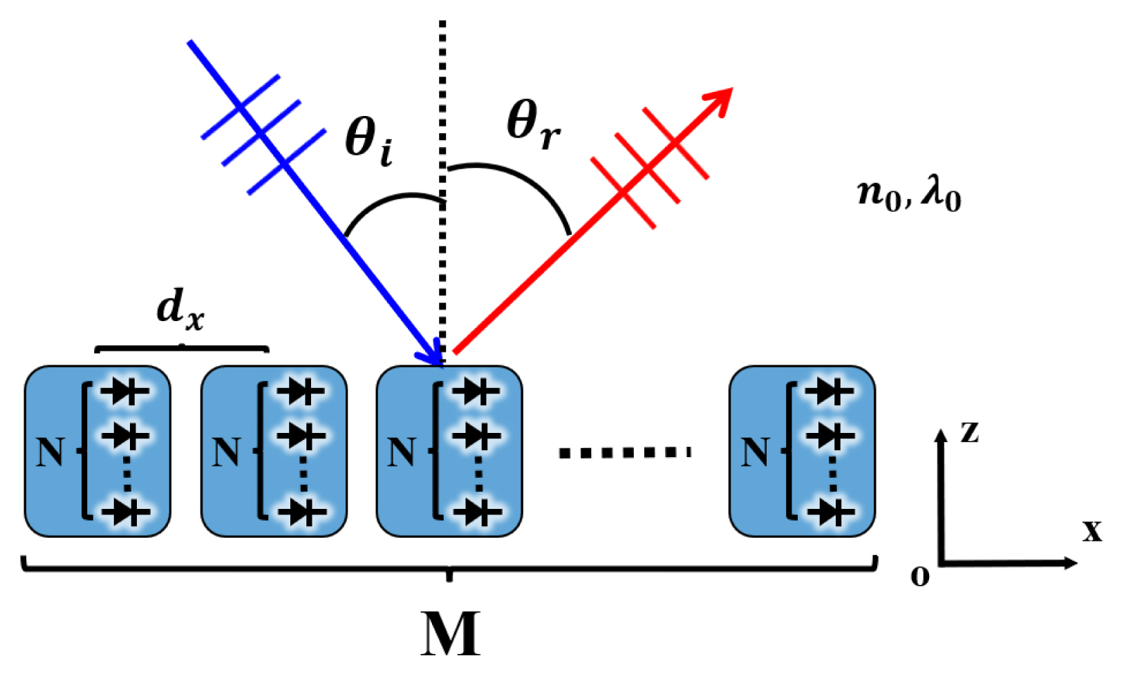
PIN diode-based N-bit RRDM.
Here, n0 indicates the refractive index of free space, λ0 refers to the wavelength in free space, and dx represents the distance between adjacent cells. Following this, the N-bit RRDM implements the reflection phase acquired from Eq. (2) using the quantized N-bit phase. Therefore, the reflection phase (ΦN–bit(m)) of the mth unit cell in the N-bit RRDM can be expressed as Eq. (3):
Here, R(X) refers to an integer value obtained by rounding off X. The phase of the unit cell is quantized to only 0° and 180° when N is 1. Subsequently, as N increases, the quantized phase difference becomes smaller. At the same time, a continuous retrodirective metasurface (continuous RRDM), which controls the phase continuously, can implement a perfect reflection phase gradient, with the controlled reflection phase (ΦContinuos(m)) of the mth unit cell being equal to ΦIdeal(m). Due to this difference between the N-bit and continuous RRDMs, they operate differently. Furthermore, the array factor (AF(θ)) of the N-bit and continuous RRDMs can be calculated by changing N from 1 to 4. Fig. 2 shows the normalized value of AF2 on using 1, 2, 3, and 4-bit RRDMs, with the retroreflection angles being 5° and 25°. The cell distance is 0.35λ0 and the number of cells is 20.
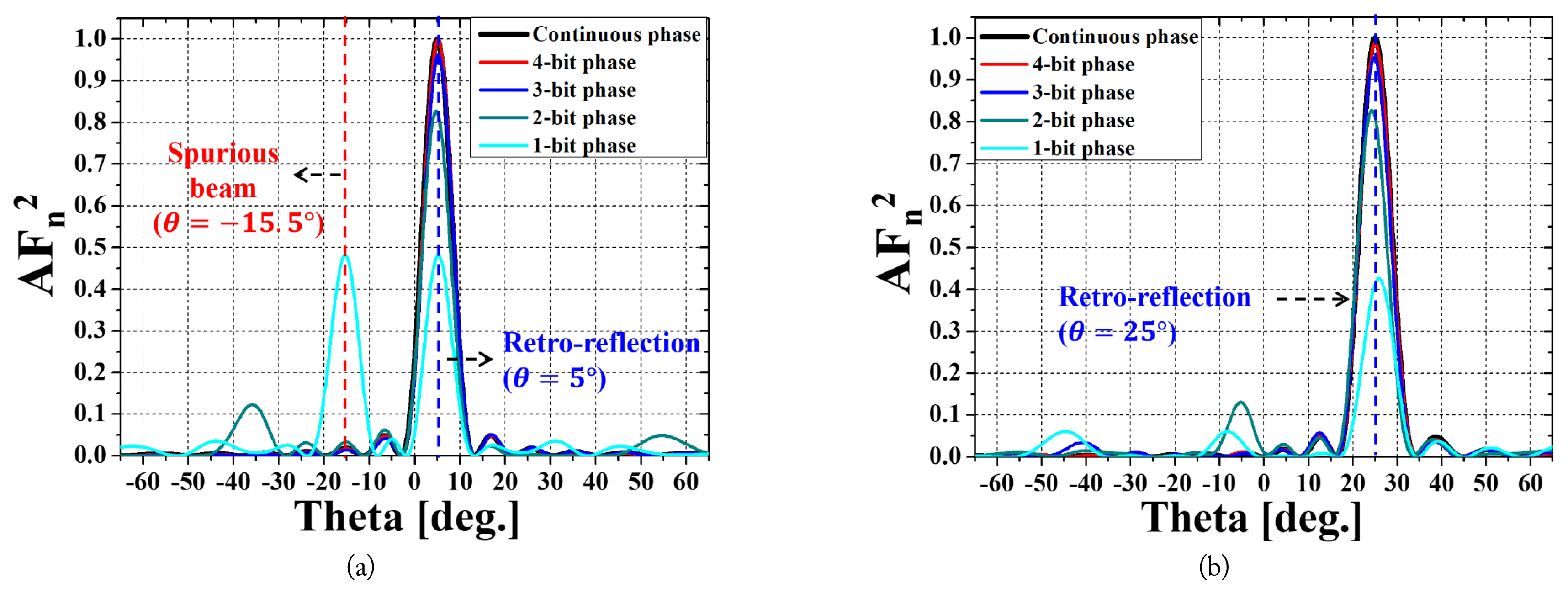
Comparison of the array factor (AF2) on using the 1-, 2-, 3-, and 4-bit RRDMs: (a) 5° and (b) 25°.
Moreover, since the magnitude of AF(θ)2 and the gain of the beam are proportional to each other, it is possible to assess the reduction in gain caused by the phase quantization by comparing the AF(θ)2 of the N-bit and continuous RRDMs. The ratio of the maximum peak value (Peak) of the N-bit and continuous RRDMs can be considered the quantization efficiency (ηQuantization), as shown in Eq. (4) [10]:
In accordance with Fig. 2, the value of ηQuantization converges to 1 as N increases, indicating an improvement in the gain reduction.
Meanwhile, in the case of 1-bit (N = 1) RRDM, Fig. 2(a) shows a spurious beam error at the same level as the main lobe occurring in an undesired direction (θ=−15.5°). This spurious beam was analyzed using array factor theory, according to which the AF(θ) of the N-bit RRDM (AFN–bit(θ)) can be denoted as Eqs. (5) and (6), noted below:
Here, k0 (=2π/λ0) indicates a propagation constant in free space and ΔΦN–bit(m) denotes a difference in the reflection phase between the mth and m–1th cells when retro-reflection occurs in the N-bit RRDM. In addition, ΨN–bit(m,θ) refers to a progressive phase—the relative phase between the mth and m–1th cells in the direction θ°.
With regard to the N-bit RRDM, let us consider defining ΨN–bit(m,θre) and AFN–bit(θre) as the progressive phase and the array factor in the θre(=−θi) direction, respectively. Furthermore, let us consider defining ΨN–bit(m,θs) and AFN–bit (m,θs) as the progressive phase and the array factor in the θs direction—in which the spurious beam error occurs— respectively. Considering these assumptions, according to Fig. 2, since the spurious beam error is of the same level as the main lobe (retro-reflection), it can be accomplished that AFN–bit(θre) =AFN–bit (m,θs). This can be expressed as Eqs. (7) and (8), since AFN–bit(θ) represents the even function of ΨN–bit(m,θ).
Furthermore, since θre is equal to − θi, Eqs. (7) and (8) can be formulated as Eqs. (9) and (10), respectively, when retroreflection occurs.
Here, a is an integer. Notably, Eq. (9) has a quantization term (ΔΦN–bit(m)), which is satisfied for all m only when N = 1. Therefore, Eq. (9) represents the spurious beam error information in the 1-bit RRDM. Meanwhile, since Eq. (10) does not contain the quantization term (ΔΦN–bit(m)), it can be satisfied, regardless of N. Effectively, this is similar to the conditions under which the grating lobe occurs.
III. RESULTS AND VERIFICATION
The average value of ηQuantization, calculated by changing the dx and θre, were found to be 43.6% for 1-bit, 82.2% for 2-bit, 95.3% for 3-bit, and 98.8% for 4-bit. The number of spurious beam errors is presented in Fig. 3 in terms of the dx and θre by considering the results obtained from Eqs. (9) and (10). For instance, in the 1-bit RRDM, no spurious beam error occurs if the cell distance is 0.35λ0 and the retro-reflection angle is 25°, as shown in Fig. 3(a). Meanwhile, when the retroreflection angle is 30° and the cell distance is 0.75λ0 in the 2- bit RRDM, one spurious beam error occurs, as shown in Fig. 3(b), with the angle derived using Eq. (10) being −56.4°.

Number of spurious beam errors: (a) results for the 1-bit RRDM and (b) results for the N-bit RRDM (N ≥ 2).
Fig. 4 presents schematic diagrams of the simulations and the measurement method employed to verify the analyzed results. Notably, this study adopted the ring patch structural unit cell used in [10] as the 1-bit RRDM’s unit cell. The measurement and simulations were conducted at 10.1 GHz for the 1-bit RRDM, arranged as 12 × 12 (126 mm × 126 mm). Each unit cell (10.5 mm × 10.5 mm) was mounted with one PIN diode [13], whose phase was controlled by a 1-bit by switching the PIN diode on/off. In Simulation 1, as depicted in Fig. 4(a), the bistatic RCS result is obtained by simulating a case in which the incident wave is a plane incident wave moving in the direction (25°, 0°). In Simulation 2, the incident wave is radiated from the Tx horn antenna fixed at (60 cm, 25°, 0°), resulting in scattered power patterns that indicate the relative power value of the wave scattered in the 1-bit RRDM. This phenomenon bears the same meaning as the RCS, which expresses scattered power in an area.

Schematic diagram of the simulation and measurement: (a) Simulation 1, (b) Simulation 2, (c) Simulation 3, and (d) measurement.
In both Simulation 3 and the measurement, the Tx horn antenna is fixed at (60 cm, 25°, 0°), while the Rx horn antenna is moved to the arc of (60 cm, θ°, 0°), ultimately resulting in S21. Subsequently, the bistatic RCS was calculated using S21 and the radar range equation. It is noted that the retro-reflected wave can be measured from S1 using only one Tx horn, while the other waves can be measured using the Tx and Rx horn antennas.
The bistatic RCS and the scattered power pattern obtained from the three simulations and the measurement were normalized and plotted, as depicted in Fig. 5. For normalization, each simulation and measurement was performed again using the conducting plate (126 mm × 126 mm). Subsequently, the resulting RCS values in the specular direction were used as the normalization factor. As observed in Fig. 5, the results of the simulations and the measurement conducted for the different methods exhibit similar shapes. The main lobe is formed at around 25°, indicating a retro-reflection angle, with no spurious beams. Meanwhile, the beam around −25° is in the specular direction, exhibiting a lower level than the main lobe. Overall, the measured results indicate relatively good agreement with the simulated results, thus verifying the analysis and theory of RRDM presented in this study.
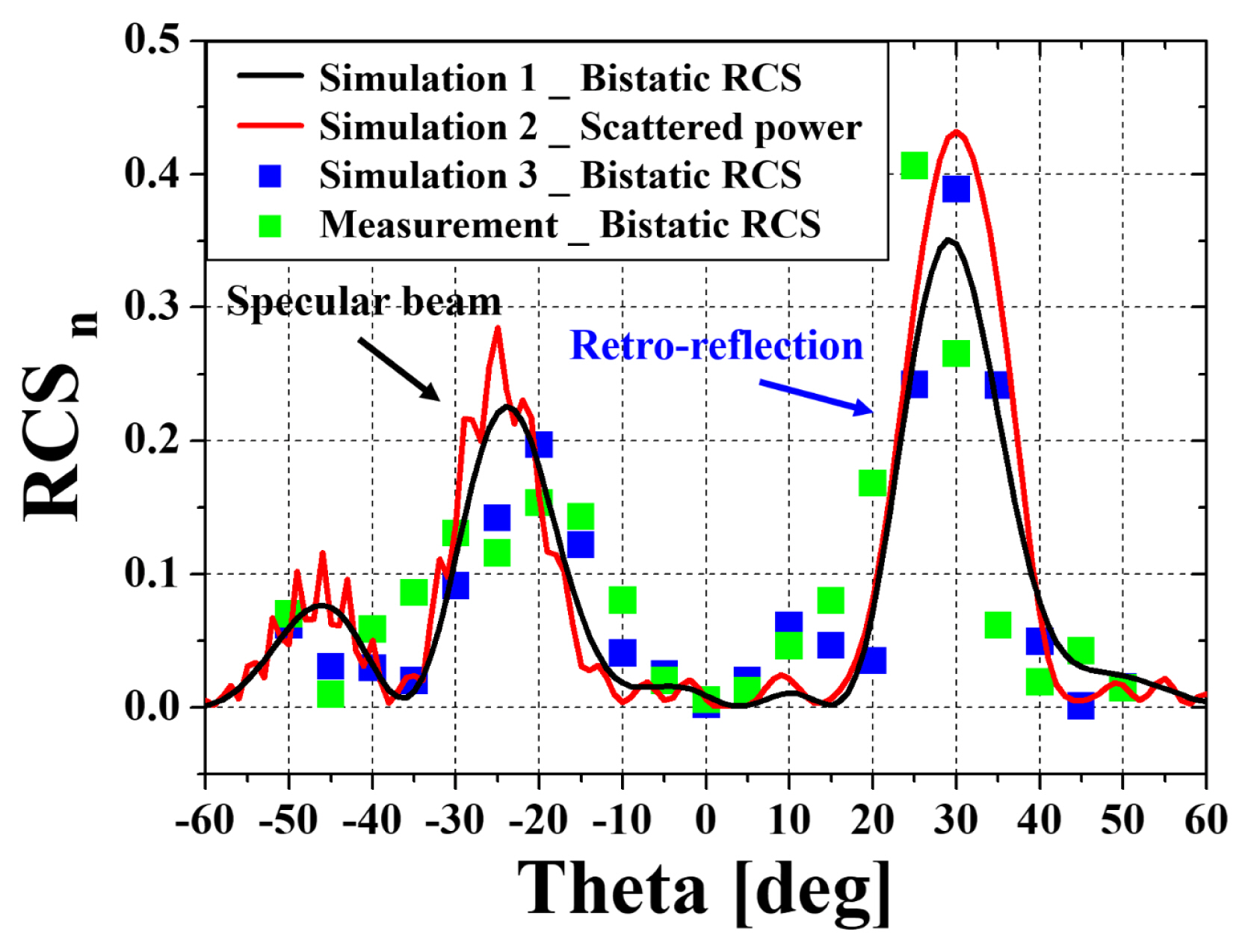
RCS results of the simulations and the measurement.
IV. CONCLUSION
This paper proposed a PIN diode-based N-bit RRDM that can electronically control the retro-reflection angle. The array factor of the N-bit RRDM achieved a lower value than that the continuous RRDM due to phase quantization, resulting in gain reduction. However, undesired spurious beam errors still occurred. This phenomenon was theoretically analyzed and arranged using generalized Snell’s law and the array factor theory. The obtained results show that the gain reduction can be controlled by the selection of N. In particular, it was found that when N increased from 1 to 2, the quantization efficiency increased dramatically from 43.6% to 82.2%. Furthermore, it was established that the occurrence of a spurious beam can be controlled by the selection of dx and θre. Moreover, the theoretical results were successfully verified through simulation and measurement.
ACKNOWLEDGMENTS
This work was supported by the National Research Foundation of Korea, funded by the Ministry of Education through the Basic Science Research Program (Grant No. 2015R1A6A1A03031833).
References
Biography

Hae-Bin Jung, https://orcid.org/0000-0002-3254-231X received his B.S. and M.S. degrees in electronics and electrical engineering from Hongik University, South Korea, in 2021 and 2023, respectively. He is currently a research engineer at LIG Nex1, Yongin, South Korea. His research interests include array antennas and metasurfaces.

Jeong-Hae Lee, https://orcid.org/0000-0002-5135-6360 received his B.S. and M.S. degrees in electrical engineering from Seoul National University, South Korea, in 1985 and 1988, respectively, and his Ph.D. in electrical engineering from the University of California at Los Angeles, Los Angeles, USA, in 1996. From 1993 to 1996, he was a visiting scientist at General Atomics, San Diego, CA, USA, where his major research initiatives were the development of a millimeter-wave diagnostic system and studying plasma wave propagation. Since 1996, he has been working at Hongik University, Seoul, South Korea, as a professor in the Department of Electronic and Electrical Engineering. He was the president of the Korea Institute of Electromagnetic Engineering and Science in 2019. He is currently the director of the Metamaterial Electronic Device Center. He has more than 120 articles published in journals and 70 patents. His current research interests include metamaterial radio frequency devices and wireless power transfer.