Investigation of Pulse Characteristics of a Novel Cylindrically Slotted Cloaked Antenna
Article information

Abstract
This study numerically examines the pulse radiating capacities of a novel cylindrically slotted cloaked antenna. The performance of the cloaks for the proposed structure is investigated using the scattering cancellation principle. Furthermore, the pulse radiating performance of the proposed antenna is extensively evaluated by employing a figure of merit. The results show that the proposed antenna exhibits a maximum pulse radiating capacity at 67.5° for the theta-polarized angle, while its pulse radiating performance is independent on the phi-polarized angles.
I. Introduction
Cloaking objects has recently attracted great interest from the industrial and defense sectors [1, 2]. The process of cloaking makes certain objects invisible at a specific frequency, which is a highly desirable characteristic in recent electronic devices or in crowded sensors mounted on a platform with highly restricted space [1, 2].
With the recent trend of minimizing the size of antennas while increasing their number in a given platform [1–3], the intensive arrangement of antennas within highly dense areas has triggered severe electromagnetic interference (EMI) issues. This is because the neighboring antennas are greatly affected by the re-radiation or scattered fields generated from objects, resulting in the degradation of the antenna characteristics at the neighboring frequency, which eventually deteriorates the overall performance of the platform [1–3].
The novelty of this letter lies in its attempt to conduct a fundamental investigation into the pulse radiating characteristics of a cylindrically slotted cloaked antenna. To the best of our knowledge, this is the first study to characterize the cloaked performance of this proposed structure in terms of frequency and time domain by simultaneously operating and cloaking at a specific frequency.
II. Cylindrically Slotted Cloaked Antenna
Fig. 1 presents the configurations for a cylindrically slotted cloaked antenna proposed and designed by CST Microwave Studio (http://www.cst.com). The core structure consists of a cylindrically slotted antenna that is circumferentially created for a slot, with its aperture, metasurface, and host material filled with a dielectric constant to prevent a shorted circuit. This structure is grounded on a circumferentially continuous metallic sheet. The operating frequency of the slotted antenna is primarily determined by two parameters—slot length (slen) and slot width (sw). Meanwhile, its cloaked frequency is independently controlled by the parameters of the metasurface—the dielectric constant of the host material, the space between the unit cell structure (mg), and interval of the unit cell of the metasurface (mp). All these parameters represent functions of the surface impedance of the metasurface, which eventually accelerates the anti-phase current flowing on the metasurface to ultimately cancel the scattering fields arising from the cylindrically slotted antenna at cloaked frequency. The cloaked frequency is characterized by controlling the components of the metasurface. Notably, extensive studies have been conducted on this topic, including metasurface parametric investigations aiming to control the cloaked frequency, as evident in [1, 3–5].

Configuration of the proposed cylindrically slotted cloaked antenna structure: (a) cylindrically slotted antenna and (b) metasurface coated cylindrically slotted antenna.
Fig. 2 presents a summarized parametric study of the proposed antenna to investigate its characteristic variations. The parameters considered for determining the operating frequency (f0) of the cylindrically slotted cloaked antenna are the slot length and width. Moreover, the parametric study is performed in such a way that only the slot length or width vary, while the other parameters remain fixed. Therefore, the characteristics of a slot length varying from 5 to 6.5 mm are investigated by maintaining a fixed slot width of 17 mm, as shown in Fig. 2(a). Similarly, a fixed slot length of 6.5 mm is maintained to examine the characteristic variations on changing the slot width from 14.5 to 16.2 mm, as shown in Fig. 2(b). Fig. 2(a) and 2(b) show the resonant frequency shifts resulting from the slot length and slot width variations, respectively. In this context, it should be noted that the cloaked frequency of fc is not affected by these parameters.

Characteristic variations of the cylindrically slotted cloaked antenna: (a) slot length (slen) variations and (b) slot width (sw) variations.
III. Characteristics of Cylindrically Slotted Coated Antenna
After conducting the numerical estimations, as mentioned above, the final antenna with slen of 6.5 mm and sw of 15.6 mm is specifically designed to simultaneously operate at f0 (2.57 GHz) and cloak at fc (3 GHz). These two phenomena can be confirmed by observing the field distribution near the antenna, as shown in Fig. 3. Once the transverse magnetic (TMz) polarized plane wave is incident toward the y-axis, the electric field near the antenna is investigated. The field is observed to be severely destructive at the f0 (2.57 GHz) incident wave due to strong scattering by the antenna. In contrast, the field is uniform near the antenna at fc (3 GHz), which is characterized by a cloaked frequency.

Electric field distribution near the proposed antenna with the same dynamic ranges: (a) field investigation at f0 (2.57 GHz) and (b) field investigation at fc (3 GHz).
Fig. 4 shows the radiated field distribution of the proposed antenna at both the operating (f0) and cloaked (fc) frequencies on the XOZ and XOY planes. The original coordinates of the structure are presented in Fig. 1. At the same dynamic field intensity, the radiated electric field of the proposed antenna at the operating frequency (f0) for both planes is observed to be quite well developed, leading to successful propagation. However, in the case of the electric field of the proposed antenna at cloaked frequency (fc), both planes seem to be not entirely developed, possibly because most of the power the almost power is reflected by the antenna.
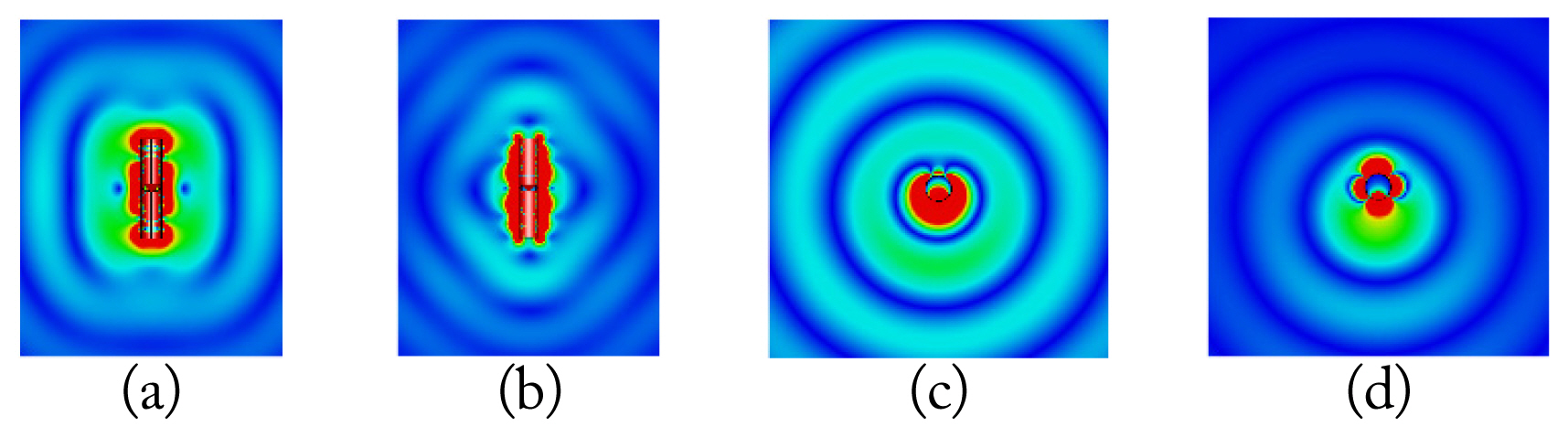
Electric field distribution characteristics: (a) XOZ-plane at f0 (2.57 GHz), (b) XOZ-plane at fc (3 GHz), (c) XOY-plane at f0 (2.57 GHz), and (d) XOY-plane at fc (3 GHz).
As shown in Fig. 5, the pulse radiating aspect of the proposed antenna is also investigated in this study. The antenna’s far-field radiated electric pulse is explored for various angles, considering the phi- and theta-polarized angles on the XOZ and XOY planes at both the operating (f0) and cloaked (fc) frequencies. Here, the radiated electric pulse is obtained based on the following equation [6]:
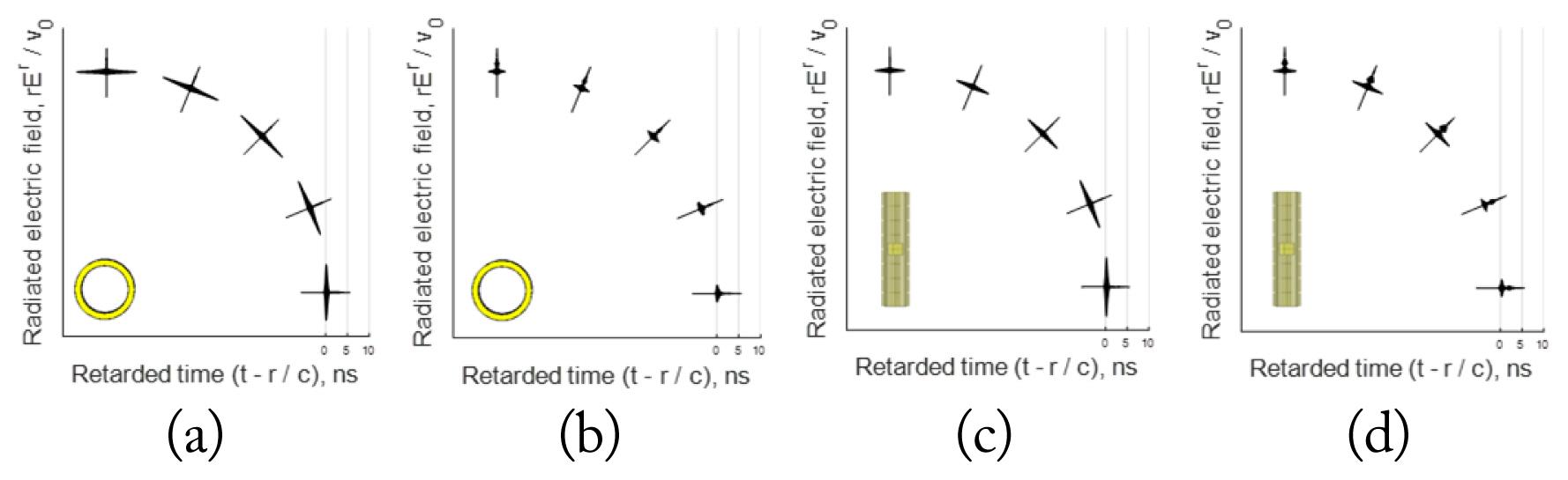
Far region radiated electric field pulse waveform at various angles: (a) φ – pol. at f0 (2.57 GHz), (b) φ – pol. at fc (3 GHz), (c) θ – pol. at f0 (2.57 GHz), and (d) θ – pol. at fc (3 GHz).
where
where v0 is the unit amplitude of 1 V, σ is the parameter of the pulse width in the time domain or the bandwidth in the spectrum, and fp is the peak frequency in the spectrum, which can refer to the operating or the cloaked frequency considered in this study.
Fig. 5(a)–5(d) show the far-field radiated electric field pulse waveform characteristics in the time domain of the theta- and phi-polarized angles from 0° to 90°, with 22.5° intervals at specific operating and cloaked frequencies. As shown in Fig. 5(a), it is evident that the radiated electric field pulse waveform at the operating frequency is almost similar to that for each phi-polarized angle. Moreover, the far-field electric field waveform at the operating frequency, as shown in Fig. 5(c), is dependent on the theta-polarized angle. Meanwhile, the far-field electric field waveform at cloaked frequency, as shown in Fig. 5(b) and 5(d), hardly produces any radiation at various polarized angles. This can be quantitatively evaluated using a figure-of-merit (FOM), as noted below:
where fidelity is a factor that signifies the extent to which two pulses are well matched, Ein is the incident energy within a time period, while E0(f0) and Ec(fc) are the radiated electric field energy at the operating and cloaked frequencies, respectively.
Tables 1 and 2 show the summarized profiles of the FOM for the phi and theta polarizations at both the operating and cloaked frequencies. As illustrated in Fig. 5, it is numerically confirmed that although the FOM is similar for all phi-polarized angles, it is highly dependent on the theta-polarized angles, which supports the quantitative profiles. For the theta-polarized angle, the highest value of FOM is obtained at 67.5°, while it reaches its minimum at 22.5° in this regard.

Quantitative profile of FOM for φ – pol
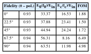
Quantitative profile of FOM for θ – pol
IV. Conclusion
In this letter, a cylindrically slotted cloaked antenna is first proposed and then numerically analyzed with regard to its pulse radiating aspects. The proposed antenna plays a dual role—radiating energy at the operating frequency and cloaking electromagnetic waves at the cloaked frequency. The operating frequency is determined by controlling the slot parameters, such as slot width and length, while the cloaked frequency is fundamentally controlled by the metasurface parameters. The proposed antenna is highly beneficial for platforms with limited available space where multiple antenna sets are placed in close proximity to each other.
Acknowledgments
This research was supported by Regional Innovation Strategy (RIS) through the National Research Foundation of Korea (NRF) funded by the Ministry of Education (MOE) (No. 2021RIS-003 and 1345370810).