I. Introduction
Most commercial wireless underwater communication techniques are based on acoustic waves as well as optical and microwaves [1]. Compared to these existing communication technologies, magnetic field-based communication in the near field is unique in terms of low propagation delay, insensitive Doppler spread and delay spread, scalable bandwidth, negligible multipath fading, low power consumption, and less susceptibility to surroundings [2]. Because of these advantages, it is a promising alternative in underwater communication. Although magnetic field-based communication has low susceptibility in nonconventional media, it remains associated with the inherent constraint of a very limited communication range [2]. In the near-field range, the magnetic field was attenuated at a rate of 1/d3, where d is the distance from the source. The solution to overcome this constraint is to take advantage of the giant magnetoimpedance (GMI) effect, which is characterized by a high magnetic field-to-voltage conversion ratio (MVCR) and the detectability of weak magnetic fields of pT/√Hz levels.
In previous studies [2, 3], to demonstrate the advantages of magnetic communication, our research team applied the validation of a high-sensitivity GMI sensor and GMI receiver at the laboratory level. In this letter, we have expanded our laboratory-level results to practical environments by using underwater media conditions and describing the validation results.
II. System Configuration and Results
This letter discusses the experimental assessment of the magnetic field communication link of a GMI receiver in the practical environment of underwater media. To verify magnetic communication, we chose the lowest frequency band (19–21 kHz), which is recommended by the International Telecommunication Union-Radio Communication Sector Study Group 1 (ITU-R/SG1) as standards of wireless power transmission. Accordingly, the experimental results were based on a carrier frequency (fc) of 20 kHz.
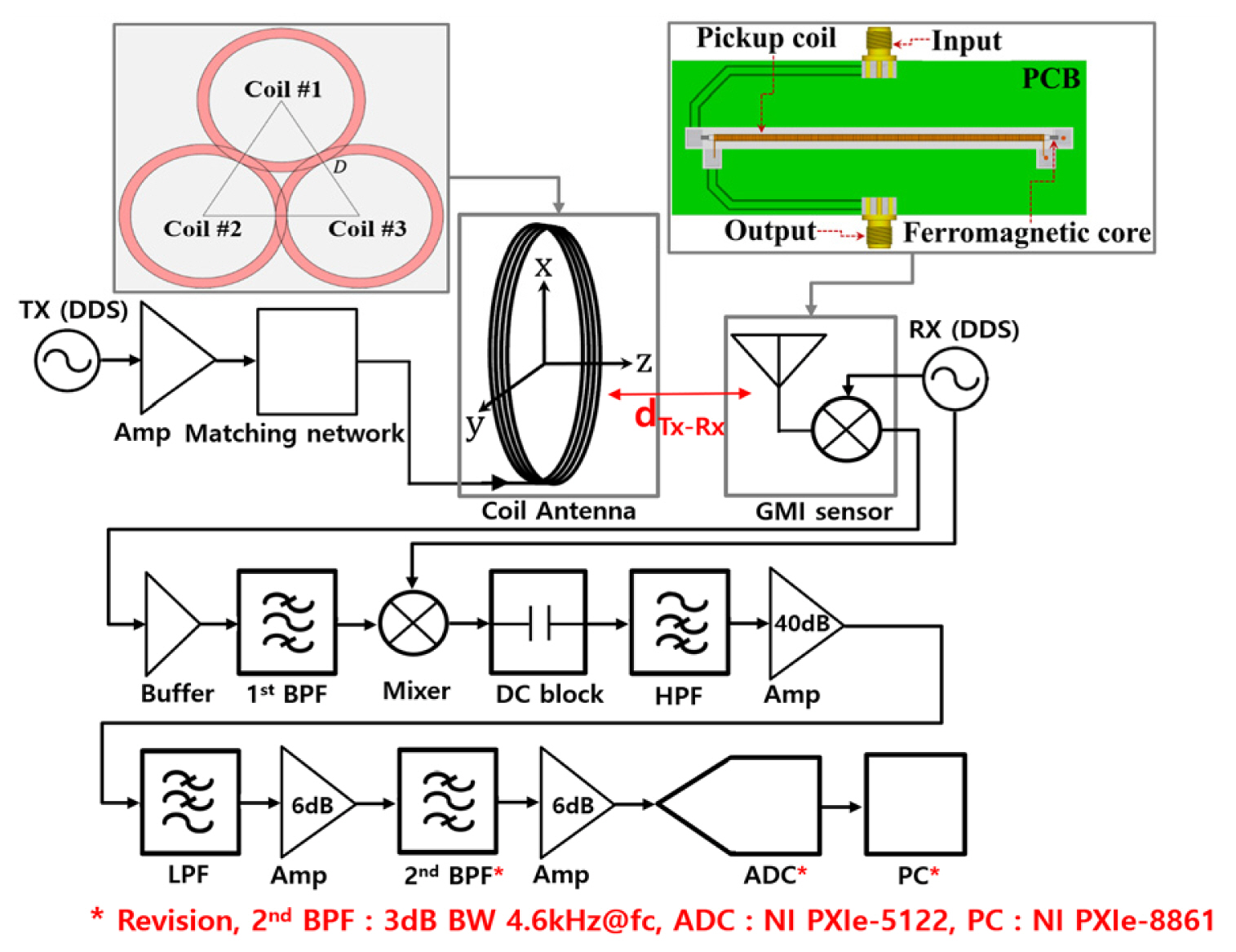
Fig. 1 shows a block diagram of the magnetic communication system based on the GMI receiver. To increase the bandwidth (BW) and communication distance, a practical transmission (Tx) antenna was replaced by triangularly arranged three-coil antennas within a square frame structure from a single-coil antenna considered in a previous study [3]. Using the triangular arrangement of three-coil antennas [4], the Tx antenna achieved a BW that is 5.6 times wider than the single-coil antenna with a BW of 100 Hz. Additionally, the aperture area was widened by increasing the outer and inner diameters (OD and ID) of the three-coil antennas. These advantages are important in terms of BW and communication distance in underwater magnetic communication. For example, when the input current of the Tx antenna was 0.1 Arms, the measured magnetic flux density at a distance of 10 m from the Tx was 17 pico-tesla (pT) for the single-coil antenna. On the other hand, for the proposed three-coil antennas, the value was 82 pT, which was approximately 4.8 times higher than that of the single coil. Therefore, the communication distance was increased by adopting the proposed three-coil antennas. The design parameters and resultant performance of the Tx coil antenna are presented in Table 1. As in a previous study [3], the GMI sensor used as a receiving element was the same, and the equivalent magnetic noise spectral density of the GMI sensor was reported as 579.6 pT/√Hz at 20 kHz. In [2, 3], the key features of the GMI receiver consisted of an ATmega-based microcontroller unit and an envelope detector, enabling only limited on-off keying demodulation. However, to increase the communication distance (dTx-Rx) and enable various demodulation scheme, the GMI receiver was improved, and its structures are shown in Fig. 1.
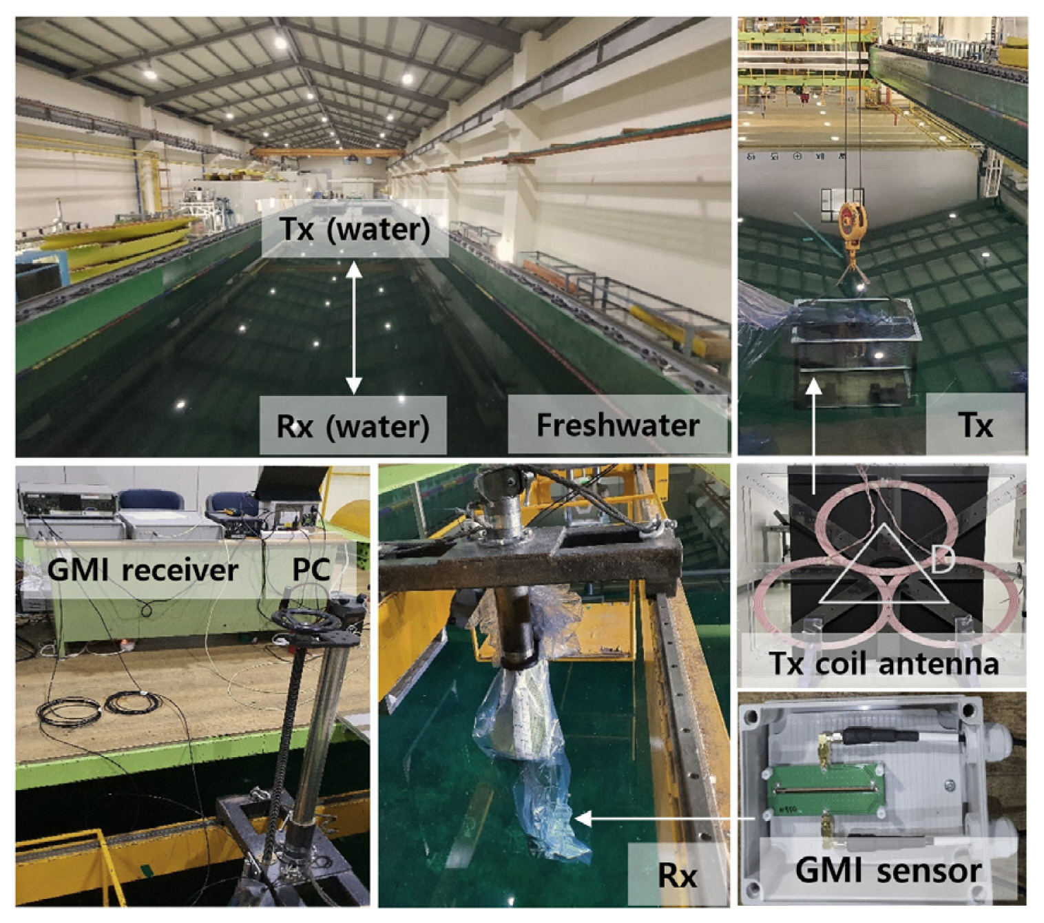
Fig. 2 shows the underwater channel test environment for the magnetic communication system using a GMI receiver. The communication media for the measurements consisted of freshwater with a conductivity of 0.001 mS/cm. The test was conducted in a large water tank site with a size of 100 m × 8 m and that contained freshwater at a depth of 3 m. Here, both three-coil antennas for Tx and the GMI sensor for Rx were sufficiently immersed in freshwater at a depth of 2 m from the water surface.
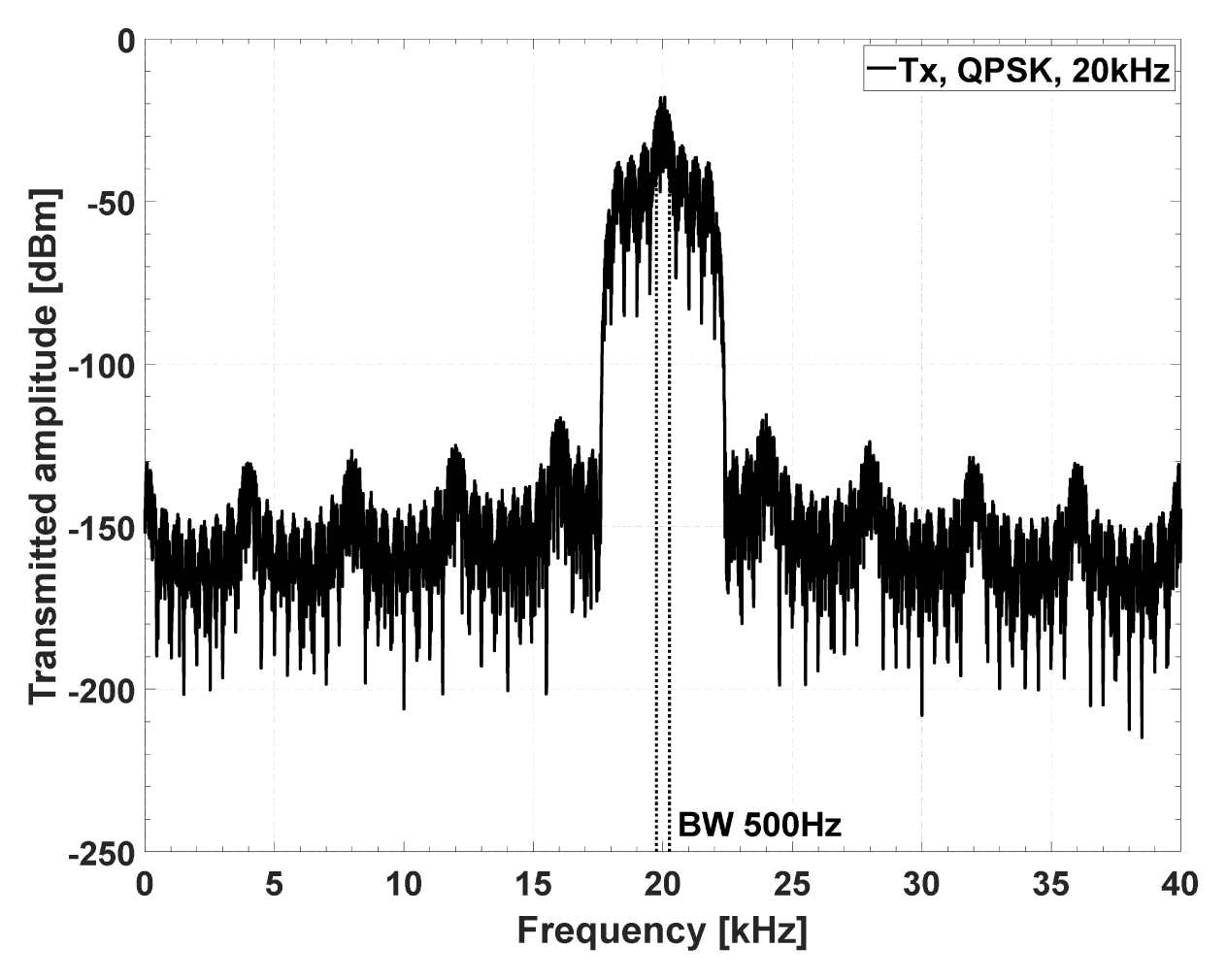
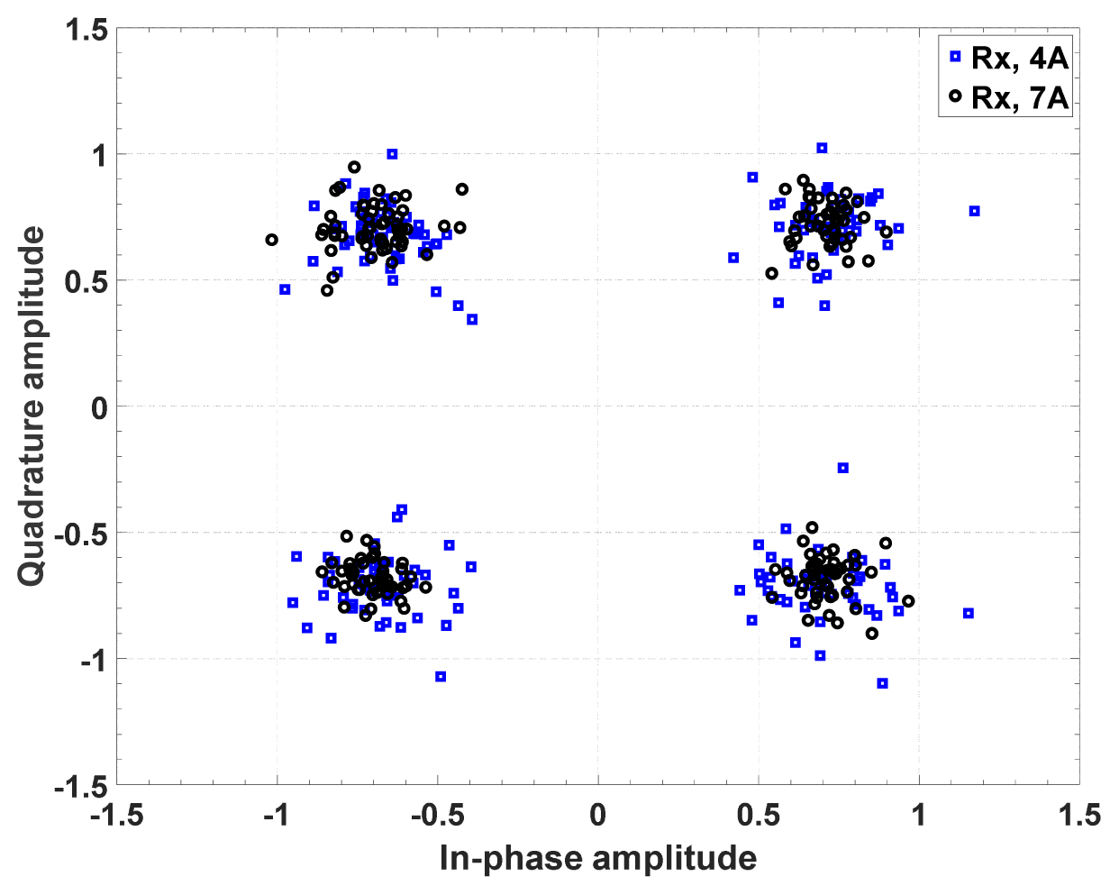
Figs. 3 and 4 show the test results of the magnetic communication link using the quadrature phase shift keying (QPSK) modulation method. The adopted BW was 0.5 kHz at 20 kHz, and a pseudo-random noise sequence code was applied (see Fig. 3). In testing the magnetic communication link, two scenarios for the minimum and stable input conditions were assumed for the Tx; one was an alternating current (AC) reactive power of 5.3 W with a current of 4 Arms flowing through the coil antenna, and the other was 16.2 W with a current of 7 Arms flowing through the coil antenna. The input conditions of the GMI sensor were 5 MHz, 3.7 Vpp, and −700 mVdc. As shown in the constellation results in Fig. 4, acceptable results were obtained for QPSK demodulation for the two scenarios at a dTx-Rx of 10 m. The measured RMS value of the error vector magnitude (EVM) was within 22.4%, which is the allowable range of the EVM standard of QPSK defined by IEEE 801.11ac, indicating satisfactory characteristics. The resultant performance of the GMI receiver is summarized in Table 2.
III. Conclusion
A practical channel environmental test of a magnetic communication system based on a GMI receiver in freshwater media environments was first performed. From the test results, the magnetic communication link was successfully verified up to a distance of 10 m with a data rate of 1 kbps using QPSK modulation-demodulation. Therefore, this letter has presented a new magnetic communication topology that enables the extension of communication distance from short range to middle and long ranges within the near field region, and successfully demonstrated the feasibility of this topology.