Efficient FDTD Simulation for the EM Analysis of Faraday Rotation in the Ionosphere
Article information

Abstract
In this work, we propose an efficient finite-difference time-domain (FDTD) simulation technique for the electromagnetic (EM) wave analysis of the Faraday rotation angle in the ionosphere. For this purpose, we first model the physical ionosphere as a scaled-down FDTD computational domain by a space-compression factor. Next, the Faraday rotation angle calculated from the FDTD simulation is calibrated by multiplying the space-compression factor. Numerical examples demonstrate that this novel space-compression-and-calibration technique can lead to a computationally efficient FDTD simulation for the EM analysis of the Faraday rotation angle without accuracy degradation.
I. Introduction
The finite-difference time-domain (FDTD) method has been widely used to analyze various electromagnetic (EM) wave propagation phenomena in complex media [1–5], such as the Earth’s atmosphere. The Earth’s atmosphere consists of the troposphere, the stratosphere, and the ionosphere. In the troposphere and the stratosphere, only refraction and attenuation phenomena affect EM wave propagation. However, EM wave propagation in the ionosphere (usually located between 60 km and 400 km in altitude) is complicated due to various propagation environments, such as the static magnetic field of the Earth and plasma [3, 4]. Note that the main effect of the ionosphere on EM wave propagation at frequencies higher than 1 GHz is the Faraday rotation angle. However, conventional FDTD simulations in the L–C bands to analyze the Faraday rotation angle require overwhelming computational burdens.
In this work, we propose an efficient FDTD simulation technique to analyze the Faraday rotation angle due to the ionosphere. For this purpose, we suggest a space-compression-and-calibration technique. Specifically, the physical ionosphere is modeled as a scaled-down FDTD computational domain by a space-compression factor (SCF), and then the extracted Faraday rotation angle is calibrated by multiplying the SCF. The reduction in the FDTD computational domain can lead to significant improvements in computational efficiency. It is noted that the idea of this proposed FDTD approach is based on the fact that the Faraday rotation angle accumulates as EM waves propagate with altitude. We analyze the Faraday rotation angle due to the ionosphere in the L, S, and C bands, using the proposed FDTD simulation with realistic ionospheric data [6, 7]. Note that the anisotropic and dispersive characteristics of the ionosphere are implemented by the simple and accurate auxiliary differential equation method to the Lorentz current equations [3].
II. Proposed FDTD Simulation Technique
The governing equations for the ionosphere are provided as follows [3, 4]:
where vc, ωp, and ωb are the collision frequency, plasma frequency, and cyclotron frequency, respectively, while ɛ0 and μ0 represent the permittivity and permeability of free space. The plasma frequency is
Here, T and Nm are the ion temperature (K) and the density of molecules (per cm3) [8]. Note that the cross-product terms in (3) cause the Faraday rotation effect. In this work, we employed realistic ionospheric data for EM wave propagation in the ionosphere. Specifically, we used realistic ionospheric data (ne, T, and Nm) for ωp and νeff from the NASA Community Coordinated Modeling Center [6], with a 0.1 km interval, and we referred to the Korean Space Weather Center [7] for B0. We used the ionospheric parameters at latitude 37° N and longitude 127° E to account for realistic EM wave propagation in South Korea. Fig. 1 shows the profiles of the plasma frequency and the effective collision frequency versus altitude. Note that the static geomagnetic field, B0, is independent of altitude.
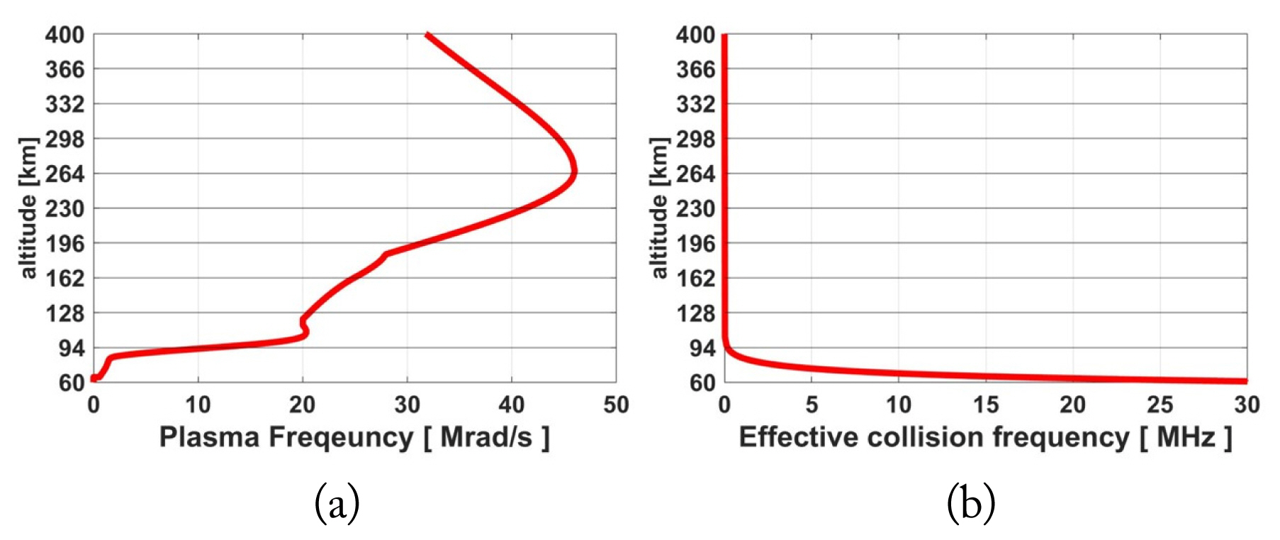
Physical ionosphere and corresponding ionospheric data: (a) plasma frequency and (b) effective collision frequency.
In general, Faraday rotation is mainly affected by the ionosphere between 60 km and 400 km in altitude. However, conventional FDTD simulations of the entire ionospheric region (340 km) require tremendous computational resources. Moreover, computational burdens increase as the frequency increases. Our numerical experiments indicate that it seems to be practically impossible to simulate the ionosphere in the L–C bands using the conventional FDTD approach.
To resolve this issue, in this work, we propose an efficient FDTD simulation technique for the study of the Faraday rotation angle in the ionosphere. Specifically, the entire ionosphere is geometrically modeled as a scaled-down FDTD computational domain, and then the calculated Faraday rotation angle is calibrated by multiplying the SCF. This space-compression-and-calibration technique is reasonable because of the accumulation behavior of the Faraday rotation angle. It is worth noting that any SCF can be used upon maintaining the realistic altitudinal variation shape of the ionospheric data.
Fig. 2 shows the scaled-down FDTD computational domain for the entire ionosphere by the SCF of 34. Note that the ionospheric data are the same as their physical counterparts. To validate our proposed FDTD simulation technique, we considered the physical ionospheric region between 94 km and 128 km, and its corresponding FDTD domain range is 1 km to 2 km in Fig. 2. All FDTD simulations were performed using the workstation (AMD Ryzen Threadripper 3990X CPU). We computed the Faraday rotation angle of EM waves through the ionosphere region in the L, S, and C bands. The incident wave is a DC-offset sinewave for the L band (fc = 1.5 GHz), the S band (fc = 3 GHz), and the C band (fc = 6 GHz). The FDTD spatial step size and the FDTD temporal step size are 0.02 m and 0.066 ns for the L band, 0.01 m and 0.033 ns for the S band, and 0.005 m and 0.0165 ns for the C band, respectively. It is noted that the FDTD spatial step sizes are determined by the point per wavelength of 10, and the FDTD temporal step sizes are chosen to satisfy the Courant stability condition. Table 1 summarizes the Faraday rotation angles computed by the conventional FDTD simulations (for the 34-km computational domain), the proposed FDTD simulations with the SCF of 34 (for the 1-km computational domain), and the proposed FDTD simulations with the SCF of 340 (for the 0.1-km computational domain). As shown in Table 1, the proposed FDTD simulation results agree very well with the conventional FDTD simulation results. Table 2 summarizes the CPU times for each FDTD simulation. The CPU times of the proposed FDTD simulations are significantly less than those of their conventional counterparts. As shown in the tables, the proposed FDTD technique achieves a significant improvement in computational efficiency while maintaining high accuracy.

Scaled-down FDTD computational domain for the physical ionosphere by the SCF of 34: (a) plasma frequency and (b) effective collision frequency.

Faraday rotation angle
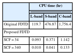
CPU time
Now, we investigated the realistic EM wave propagation characteristics in the entire ionosphere (from 60 km to 400 km in altitude) using the proposed FDTD simulation technique. Fig. 3 shows the Faraday rotation angle at several observation points. As shown in Fig. 3, the Faraday rotation angle increased as the altitude increased, and the operating frequency decreased.

Faraday rotation angle in the entire physical ionosphere.
III. Conclusion
In this work, we propose an efficient FDTD simulation approach for calculating the Faraday rotation angle in the ionosphere, based on the novel space-compression-and-calibration technique. Numerical examples were employed to validate the computational efficiency and accuracy of the proposed FDTD simulation technique. It is believed that the proposed FDTD simulation approach can be efficiently applied to predict EM wave propagation in the ionosphere for space surveillance radar applications.
Acknowledgments
This work was supported by the Agency for Defense Development Grant Funded by the Korean government (No. UC210013YD).