Transparent and Flexible Patch Antenna Using MMF for Conformal WiFi-6E Applications
Article information
Abstract
In this paper, a patch antenna with compact, flexible, and transparent properties is presented to support Wi-Fi 6E (2.4 GHz/6 GHz) applications. This antenna design was formulated based on a transparent metal mesh film (MMF), for which the average optical transparency (OTav) is 69% and the sheet resistance (Rs) is 0.1Ω/sq. The measurement results on frequency bands of 2.4–2.51 GHz and 5.87–7.04 GHz show that the average gain exceeds 5.4 dBi and 6.3 dBi with corresponding radiation efficiency rates as high as 67.8% and 70%. In addition, for the purpose of integration into aesthetic devices for smart home applications, the antenna conformed to foam and a lamp. All research outcomes here indicate that the proposed antenna maintains a directional radiation pattern, as well as transparency and flexibility, making it a potential candidate for transparent Internet of Things (IoT) applications.
I. Introduction
Devices that support Wi-Fi 5 (802.11ac) and Wi-Fi 6 (802.11ax) technology operating on the 2.4 GHz and 5 GHz frequency bands are currently experiencing broad use. However, these frequency ranges will not be feasible for high-speed, low-latency internet in the future. Therefore, the Wi-Fi 6E (extended) standard with a frequency of 5.925–7.125 GHz was developed to expand the number of devices connected to wireless internet at the same time while maintaining low latency and fast connection speeds. Many researchers have studied and designed antennas for Wi-Fi 6E [1, 2].
Transparent and flexible (T&F) antennas have attracted considerable attention in recent years owing to their light-weight, compact, low-profile, conformal design, as well as their mechanical robustness. Conductive and transparent materials have been widely studied with regard to the development of flexible electronics applications. Several types of transparent conductive electrodes are used in T&F antenna designs, such as indium zinc thin oxide (IZTO), silver-coated polymers (Ag-HTs), indium tin oxide (ITO), graphene, multilayered film (MLF), and metal mesh films (MMF) [3–6]. In comparison, MMF has traditionally been considered a reasonable choice in T&F applications owing to its great ductility, transparency, conductivity, and mechanical stability [7–10]. In earlier work [11], the sheet resistance of MMF is on the order of a few Ω/sq at optical transmittance rates exceeding 60%, which is superior to the characteristics of other transparent conductive electrodes. In addition, the junction resistance, optical transmission rate, and geometry of the MMF patterns can be altered by adjusting the mesh width, mesh spacing, and conductive material specifications. Therefore, MMF polymers are now becoming increasingly attractive and more widely used in various T&F antenna applications.
On the other hand, installing additional antennas necessitates increased complexity in device design as well as the provision of additional space. Therefore, the T&F antenna is an attractive topic in the future and has a wide range of potential applications, including automobile windshields, terrestrial communications, satellite, defense, windows, displays, and more [12, 13]. Many potential applications based on MMF are also widely studied, such as wearable technology [14], solar panels [15], windshields of vehicular platforms [16], frequency selective surface (FSS) [17], and organic light-emitting diode (OLED) touch panel for IoT applications [6, 18]. In previous works [19, 20], we investigated patch antennas using MLF and MMF in the Wi-Fi band (2.45 GHz). Nevertheless, there has been no research on how it can be used in conformal applications, along with exploiting the new frequency range used by the next generation of Wi-Fi 6E (2.45/6 GHz) technology. In addition, to reduce performance (S-parameters) changes due to attached conformal applications, the patch antenna has a ground plane at the bottom that outperforms a coplanar antenna [21]. Therefore, a T&F patch antenna design solution is proposed to overcome this problem.
In this paper, we present a T&F patch antenna for use with Wi-Fi 6E dual-band (2.45/6GHz) technology in IoT applications. We studied the properties of the MMF, such as its structure, sheet resistance, and optical transparency. The performance of the T&F antenna was carefully studied with regard to its conformal characteristics on foam and a lamp as typical examples. These results indicate the flexible integration of transparent antennas.can benefit the advancement of technology in a variety of ways.
II. Transparent Metal Mesh Film
1. Structure of the MMF
The square structure of metal mesh (MM) is selected due to its high flexibility, compactness, lightweight properties, transparency, and mechanical robustness [7]. Fig. 1 shows the dimensions (L × L) of the MMF structure. As shown in Fig. 1(a), MM is produced with a square lattice of horizontal and vertical copper strip lines on a polyethylene terephthalate (PET) substrate. The metal mesh and transparent PET layers are 2 μm and 100 μm thick, respectively. The unit cell of the MMF structure is depicted in Fig. 1(b). Copper strip lines of a certain width (w) are arranged between spaces (s) in a regular pattern and cross each other. In this way, by using the MMF, visible light can easily flow through, while the copper conductive component maintains its high conductivity.
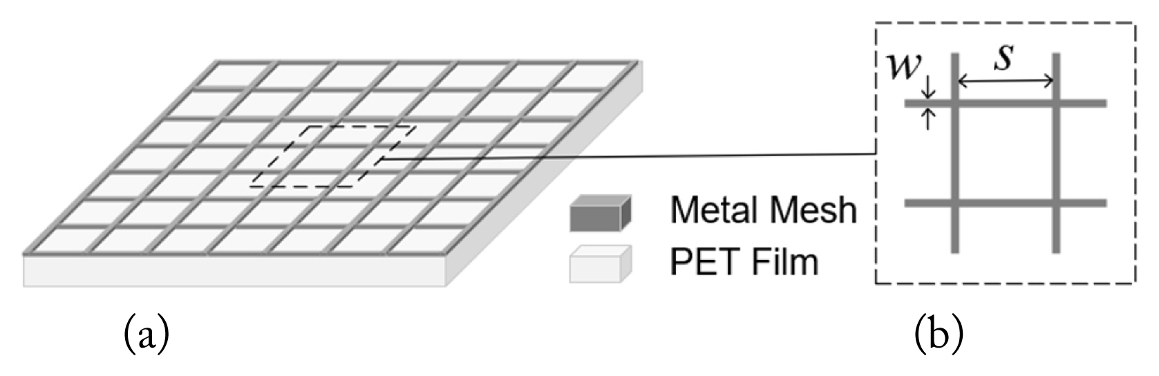
Structure of the MMF: (a) overview, (b) unit cell.
2. Optical Transparency and Electrical Conductivity of the MMF
The ratio between the non-metalized strip lines and the total area is used to determine the theoretical transparency of the MMF, which are both formed from the mesh width (w) and mesh spacing (s) of the MMF structure. In [11], the average optical transparency (OTav) of MMF was determined via
where OTPET is the average optical transparency of the PET substrate and exceeds 90% [11].
Fig. 2 shows the OTav the curve of the MMF. Here, w ranges from 5 to 50 μm, whereas s varies from 100 to 400 μm. When s is increased, OTav increases, and when w is increased, OTav decreases. This trend makes sense because a decrease in w and an increase in s result in a higher ratio of light-to-pass area, and hence an increase in the transparency of the MMF. It has been noted that there is a trade-off between transparency and conductivity in the MMF [8]: conductivity affects the performance of the antenna [6, 20, 22]. Therefore, to maintain a high level of transparency, conductivity, and possible fabrication, the mesh width, mesh space, and thickness of the MM are optimized at 21 μm, 234 μm, and 2 μm, respectively.
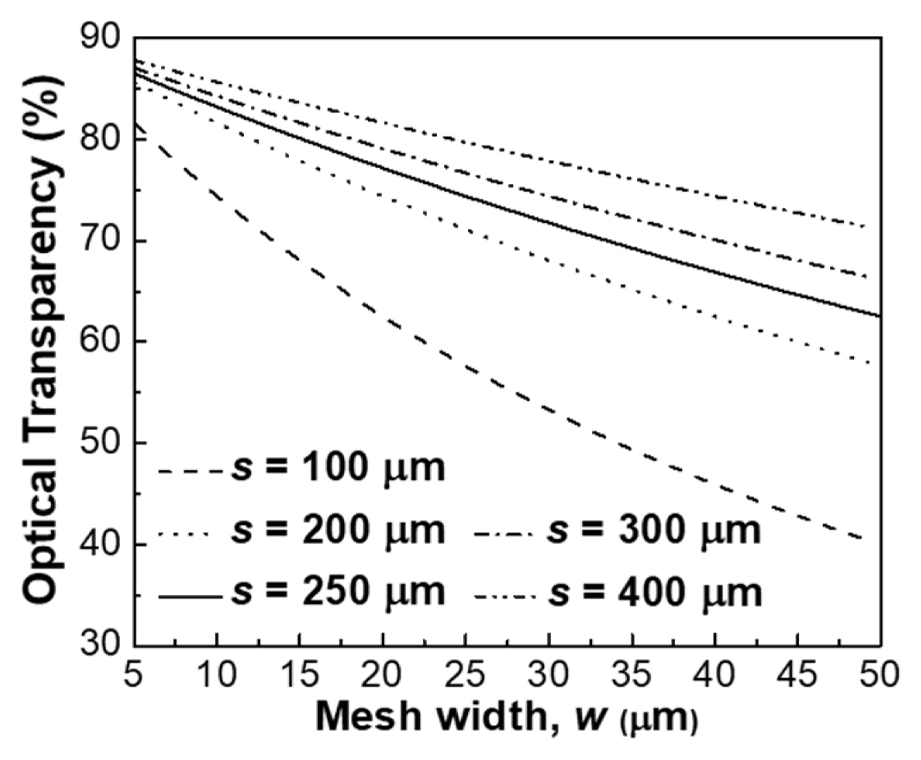
MMF theoretical transparency between mesh width (w) and mesh spacing (s).
As seen in Eq. (1), the transparency of the MMF was calculated and found to be approximately 75.7%. However, the measured results show that the OTav of the MMF slightly decreases compared to the calculated value, with the OTav being 69%. The OTav of the MMF was determined using a UV-visible spectrophotometer (T60 model). As reported in the study [11], the electrical conductivity of the MMF was determined using sheet resistance. Therefore, both the calculated and measured values are in good agreement with the average sheet resistance level of 0.1Ω/sq.
III. Transparent and Flexible Patch Antenna for Wi-Fi 6E dual-band (2.4/6 GHz) Operation
1. Dimension of the Antenna
Figs. 3(a) and 3(b) show the geometry of the proposed patch antenna. The proposed antenna design follows that of a conventional coaxial patch antenna, as reported in [23]. A PVC substrate (relative permittivity constant of ɛr= 2.7, loss tangent of tan δ= 0.022, and dimensions of Ws × Ls = 50 × 50 mm2) is used for the proposed antenna. The bandwidth of patch antennas is affected by the thickness of the substrate. To ensure that the antenna remained flexible, we used an optimized PVC thickness (h) of 2 mm. The radiator and ground components use thin MMF. The ground component covers the entire side of the PVC substrate. Table 1 shows the dimensions of the proposed antenna. The dimensions of the radiator component tapped on the other side of the substrate, are Wp × Lp = 26 × 28.5 mm2. Accordingly, the antenna has two edges that open into a rectangular groove with a width and length of Wa × La = 6.6 × 5.7 mm2, giving the proposed antenna a fundamental resonant frequency of 2.45 GHz. The feed point uses a coaxial probe with an input impedance of 50 Ω. This point has distances to the edge of the patch and substrate of Lp1=10.7 mm and Lp2= 20.45 mm, respectively.
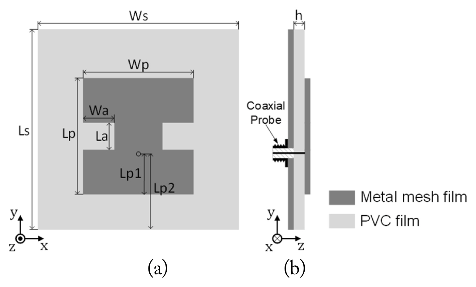
Geometry of the patch antenna: (a) top view and (b) side view.

Dimensions of the proposed transparent patch antenna
2. Simulation and Measurement Results
The simulated and measured reflection coefficients (S11 ) and the gain-total radiation efficiency of the transparent patch antennas are shown in Fig. 4. In Fig. 4(a), the reflection coefficient is measured using a vector network analyzer. The simulation result S11 shows relatively good agreement with the measurement result, showing below −6 dB (VSWR 3:1) with operating frequency ranges of 2.4–2.51 and 5.87–7.04 GHz. The measured and simulated results of the proposed patch antenna differ slightly due to imperfect fabrication.
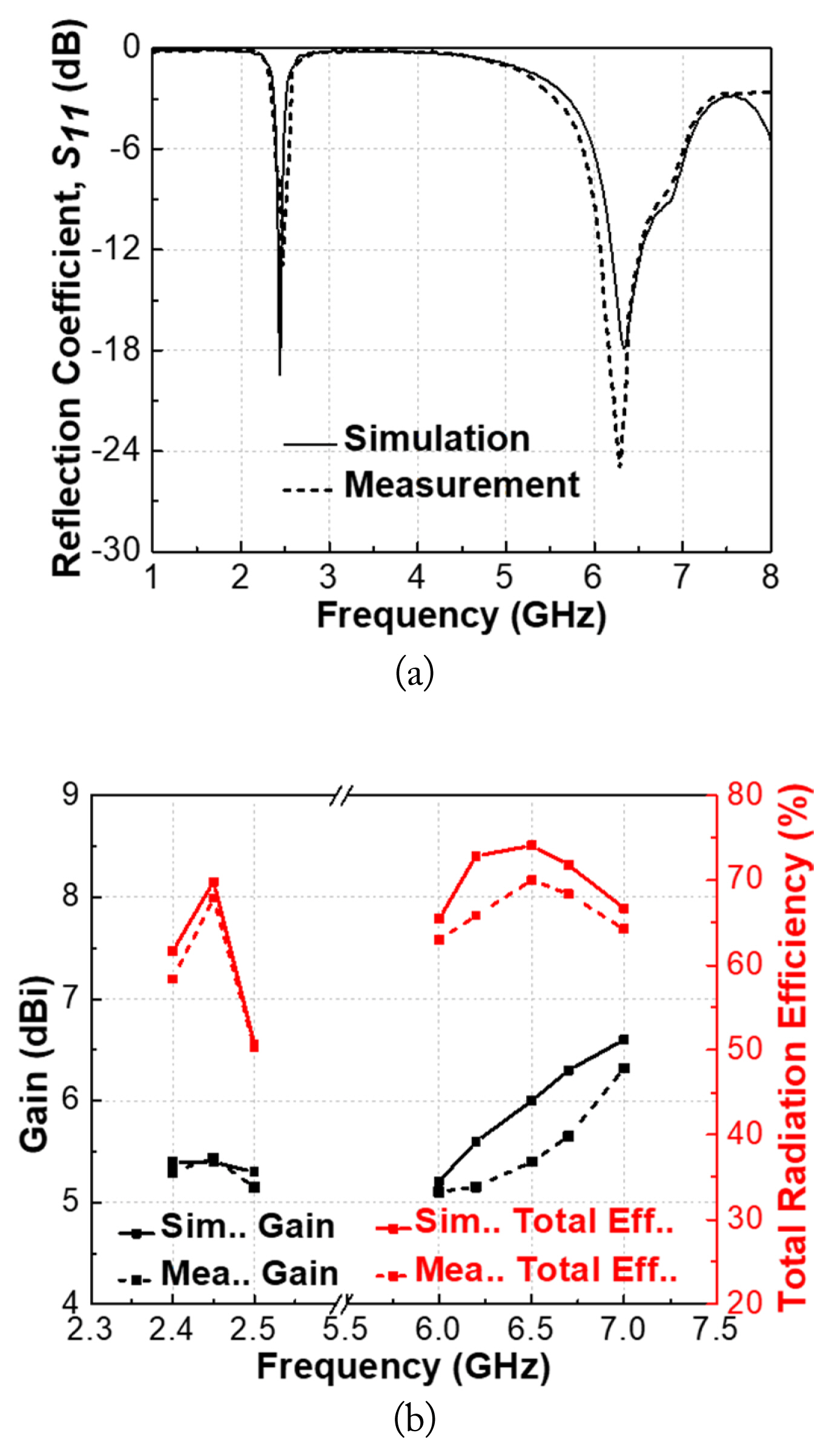
Simulated and measured the transparent patch antenna: (a) reflection coefficients (S11); (b) gain and total efficiency.
Fig. 4(b) shows the gain and efficiency outcomes when measured in an anechoic chamber. The proposed antenna shows a measured peak gain that exceeds 5.4 dBi (average value of 5.28 dBi) and radiation efficiency of up to 67.8% at low frequencies. In the entire high-frequency band, the maximum gain of 6.3 dBi (average value of 5.52 dBi) achieves a radiation efficiency exceeding 70%. It should be noted that the conductor loss, substrate loss, and subminiature version A (SMA) connector loss were not analyzed in the EM simulation and could have led to errors. Simulation results of the surface current distributions J [A/m] at phase zero (ϕ = 0°) of the antenna in both resonant frequencies (2.45 and 6.5 GHz) are shown in Fig. 5. From Fig. 5(a), when the patch operates in the 2.45 GHz band along the y-axis, the maximum current intensity is uniformly distributed from the probe to the edges and in phase. Thus, at 2.45 GHz, the patch antenna mainly works in the first-order mode [24]. Obviously, in this case, the outer edge of the antenna (along the y-direction) is the main component affecting the fundamental resonant frequency. In Fig. 5(b), at 6.5 GHz, there is a null current (close to the center of the antenna); hence, the corresponding radiated fields cancel each other out. Meanwhile, the resonant frequency is maintained by the current in the outer edges of the antenna along the y-axis.

Simulation results of the surface current distributions J [A/m]: (a) f = 2.45 GHz, (b) f = 6.5 GHz.
In Figs. 6(a)–(b), the simulated and measured co- and cross-polarized radiation patterns on the yz- and xy-planes are investigated at the center frequency. As expected, when co-polarized, the patch antenna behaves as a directional antenna on the yz-plane but exhibits nearly an omnidirectional pattern on the xy-plane. The antenna generates a directional pattern with the peak amplitude of the main lobe at 0° and 33° at 2.45 and 6.5 GHz, respectively. In addition, the measurement of the cross-polarized value was −15 to −34 dB on the yz-plane, whereas the cross-polarized value on the xy-plane was −12 to −30 dB for the whole application band. These co- and cross-polarized results confirm the validity of the proposed antenna.
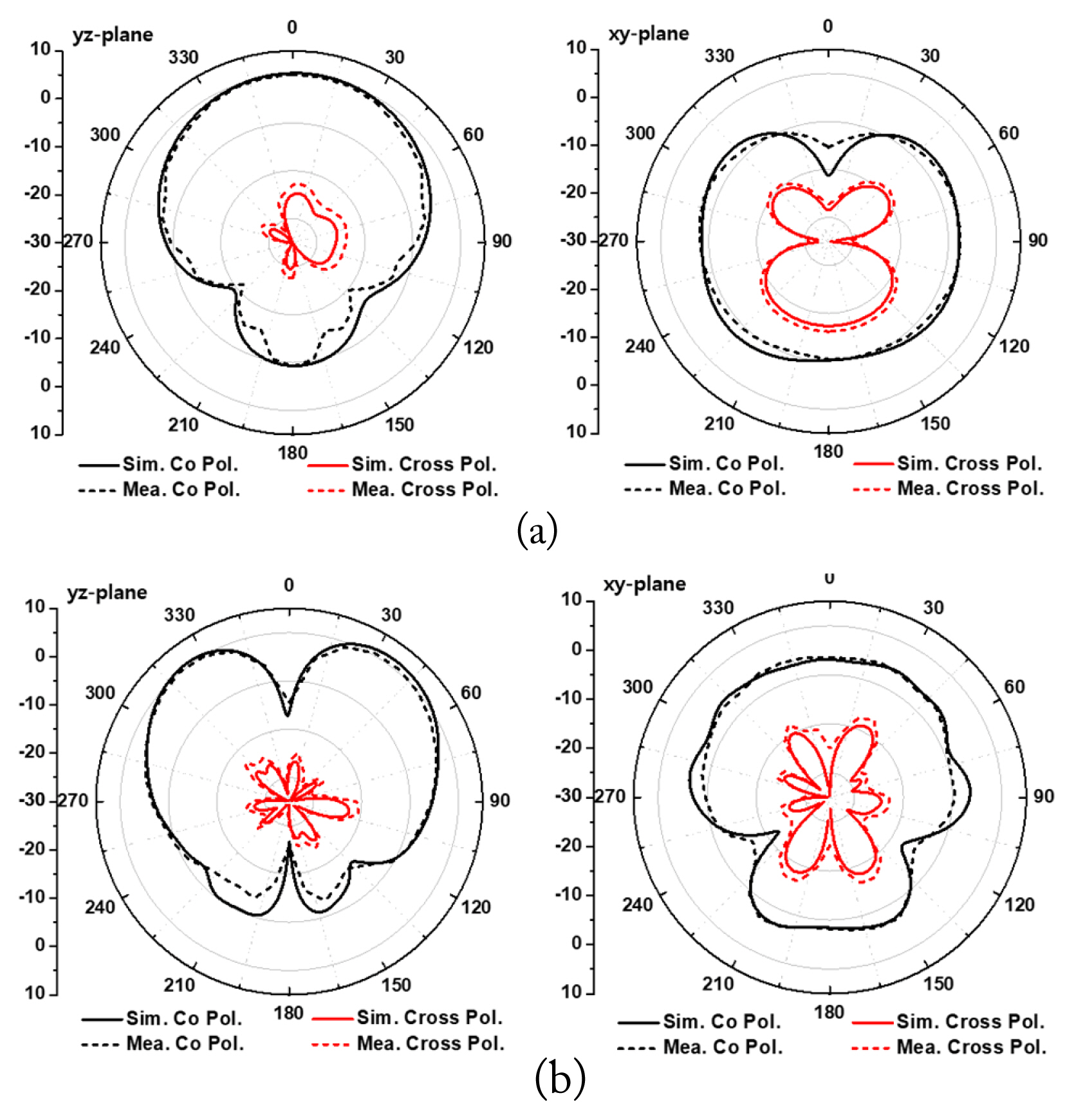
Simulated and measured co- and cross-polarized radiation patterns on the yz- and xy-planes at (a) 2.45 GHz and (b) 6.5 GHz.
Fig. 7(a) shows the measurement setup of the fabricated antenna in an anechoic chamber with a mobile antenna measurement system (0.7–8 GHz) located at the Korea Radio Promotion Association.
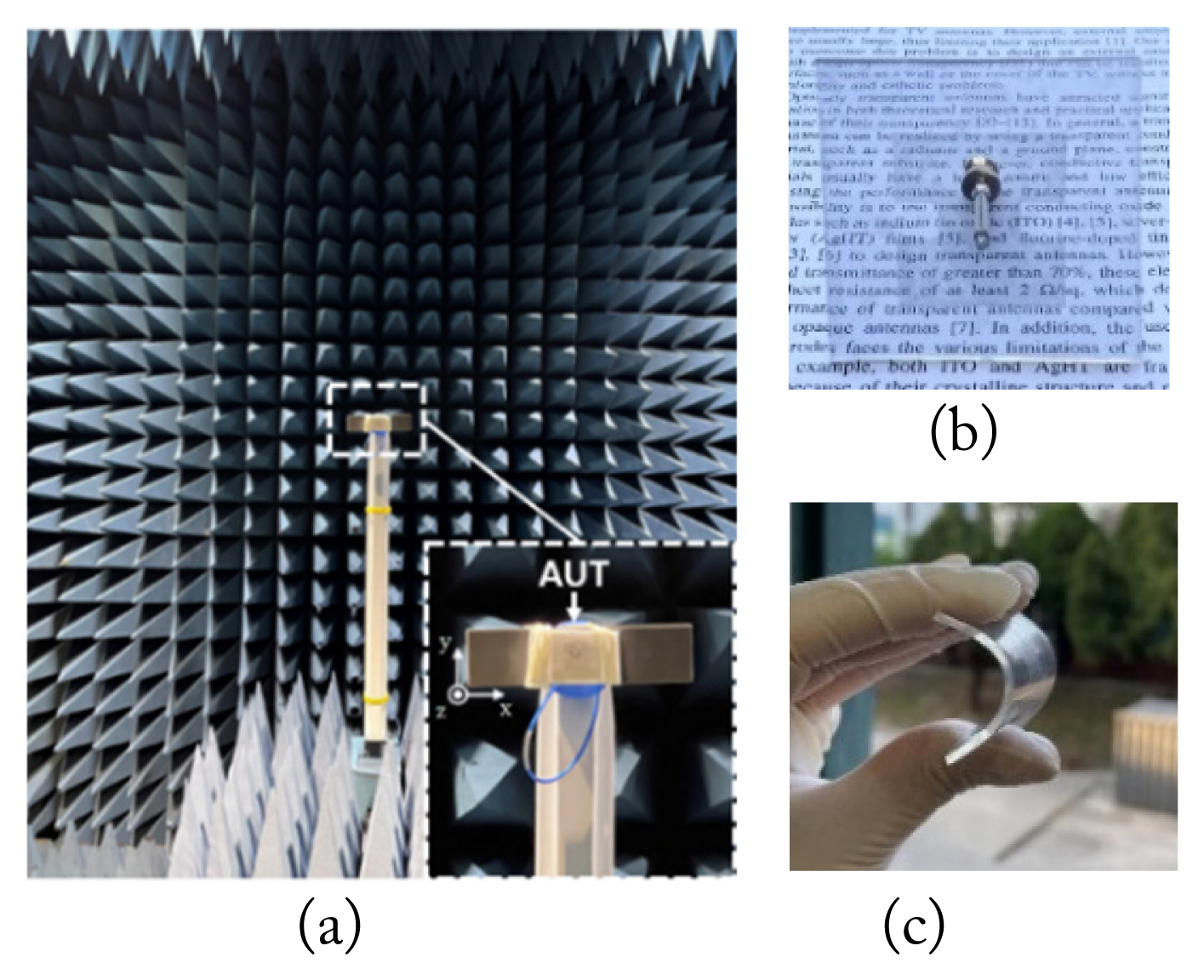
(a) Measurement setup inside an anechoic chamber, (b) fabricated patch antennas over text, and (c) a flexible antenna based on the transparent thermoplastic polymer with a PVC substrate.
The far-field pattern measurement method was used to calculate the gain and total efficiency of the antenna under test (AUT) [25]. The AUT was placed at one end of the chamber acting as a receiving antenna, the source antenna was placed at the other end as a transmitting antenna. Then, the results were analyzed via vector network analysis. In Fig. 7(b), the fabricated antenna shows transparency over text. Because of the onset temperature of MMF melting at approximately 150°C, we used a silver paste liquid (Elcoat P-100) to connect the probe feed to the feed point of the proposed antenna. As shown in Fig. 7(b), the OTav of the antenna slightly de creased (OTav ≈ 42.8%) when looking through the radiator as compared to its outer part (OTav ≈ 62%). Fig. 7(c) outlines the bending conditions of the antenna, indicating that it is flexible.
IV. Flexible Antenna Analysis
1. Changing curvature
Bending tests are applied to ensure practical operability, given that the antenna is anticipated to be bent and rolled when incorporated into flexible electronic devices. The antenna under test (AUT) was conformed to foam (ɛr=1) with two radii, R1 = 25 mm and R2 = 40 mm, to test its performance under different states of bending, as shown in Fig. 8. In Fig. 8, the measured reflection coefficient remains below −6 dB in the Wi-Fi 6E frequency range. The bandwidths of the AUT in the R1 configuration are 2.4–2.51 GHz (at 0.11 GHz, 4.5%) and 6.02–7.02 GHz (at 1 GHz, 15.3%), while the resonant band of the R2 configuration is much better, from 2.39–2.52 GHz (at 0.13 GHz, 5.2%) and 5.91–7 GHz (at 1.09 GHz, 16.8%). These results show that the resonant frequency characteristics of the AUTs tend to move slightly to the right side compared to the planar condition, and the bandwidth becomes smaller because of bending.
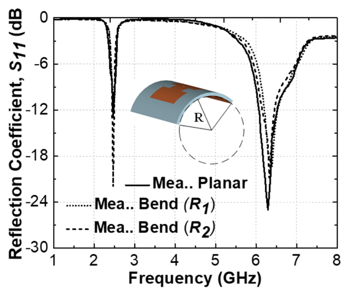
Compare the measurements of S11 bent on foam.
Figs. 9(a) and 9(b) reveal the impact of bending on the radiation pattern at the center frequencies of 2.45 GHz and 6.5 GHz. Overall, the AUT maintained its directional radiation pattern while conforming to the foam. The measurement gains achieved with bent conditions R1 and R2 at 2.45 GHz were 4.3 dBi and 3.3 dBi, while at 6.5 GHz they were 5.3 dBi and 5.5 dBi, respectively. In addition, at 2.45 GHz, the measuring total efficiency with bending conditions R1 and R2 were 65% and 60%, respectively, whereas at 6.5 GHz, they were 67.2% and 68.2%, respectively. Due to the bending effect, the AUTs had slightly decreased gain compared to the planar condition. The antenna bending on foam with R1 was impacted most by the highest bending level of 25 mm. In low frequency, this makes the antenna more directional; therefore, the gain of bending with R1 increases than R2, as shown in Fig. 9(a). The measured radiation efficiency of the antenna showed slight differences between bending with R1 and R2. This effect can be attributed to additional radiation loss caused by imperfections in measurement and fabrication.
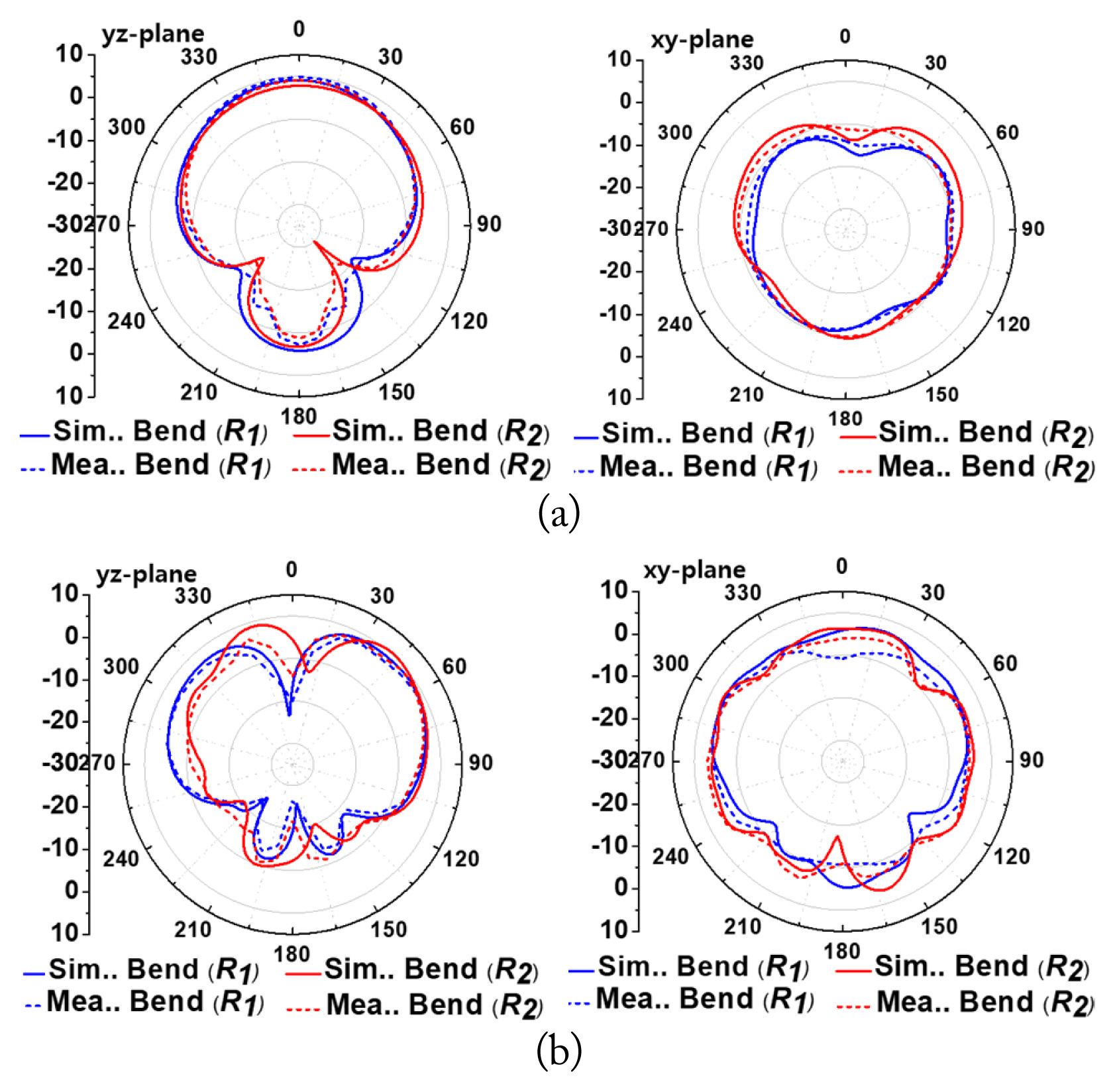
Simulated and measured 2D radiation patterns under bending on foam on the yz- and xy-planes: (a) f = 2.45 GHz, (b) f = 6.5 GHz.
2. Conformal antenna applications for the lamp
The AUT was conformed to a lamp as an example to assess its applicability in smart home applications, as shown in Fig. 10, in which the lamp is bent by nylon (ɛr=4.5), showing a radius of R3 = 75 mm. The measured fundamental frequency is maintained at 2.39–2.5 GHz. In the high-frequency range (6.15–7.15 GHz), the measured bandwidth moved slightly to the right side compared to the planar condition. This can be explained by the bending and dielectric effects of the lamp. The external material (nylon) is placed very close to the antenna. Furthermore, the electric field lines of the antenna can be influenced by the material, leading to additional capacitance or inductance, which can affect the impedance of the antenna. The flexibility test setup and measurement result (S11) for the dual-band antenna conformed to a lamp is shown in Fig. 10(b).
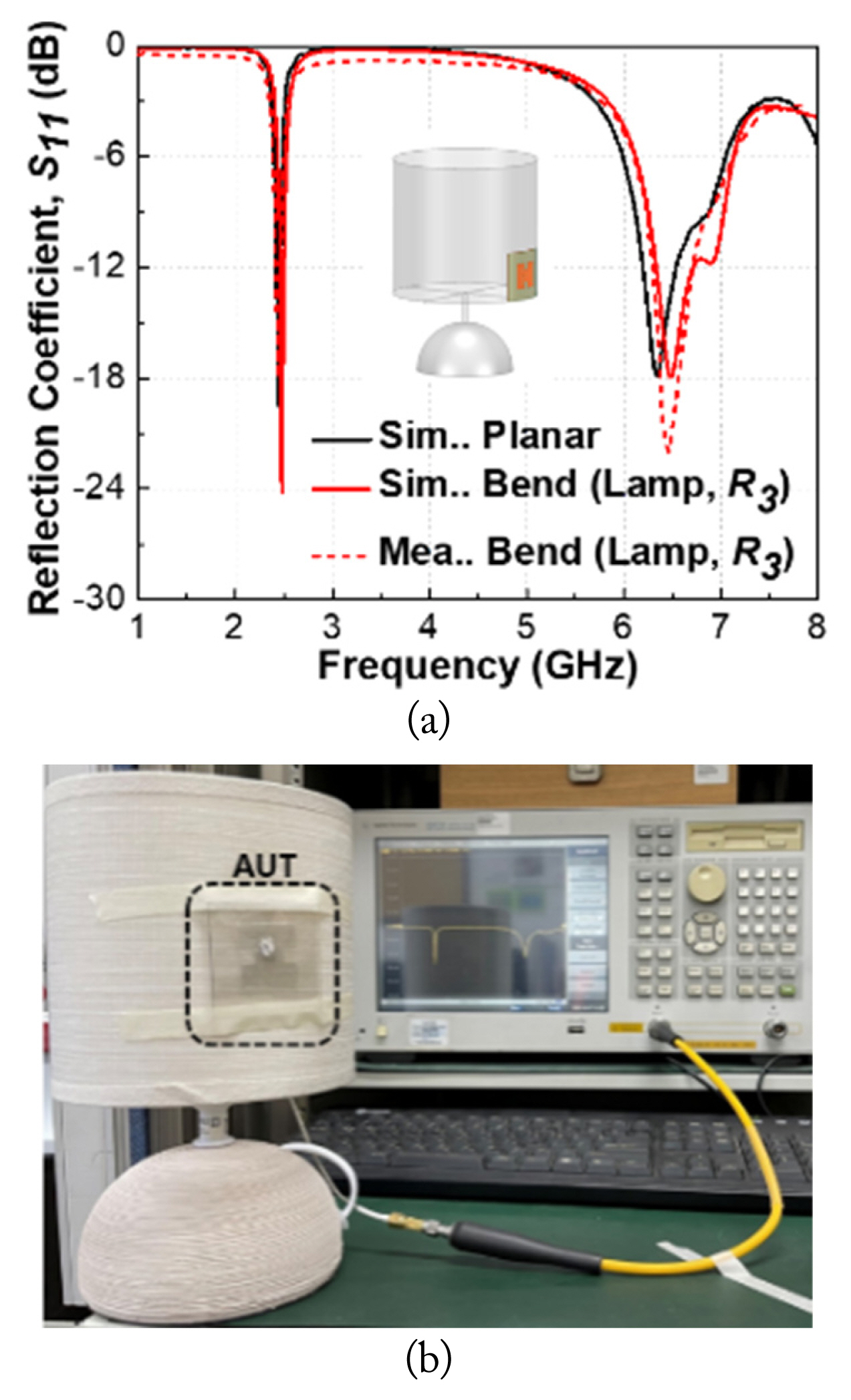
(a) Comparison of the simulations and measurements of S11 bent on a lamp; (b) measurement results of S11 bent on a lamp.
Figs. 11(a) and 11(b) show the simulated 3D radiation patterns of the proposed antenna at 2.45 GHz and 6.5 GHz, respectively. In this case, the simulated results for the AUT show a peak gain of more than 3.9 dBi, corresponding to a radiation efficiency of approximately 63% at a low frequency. Over the entire high-frequency band, the highest gain of 5.4 dBi provides a radiation efficiency of more than 68%. The radiation efficiencies show slight differences when compared to the planar condition (in low and high frequencies, the differences are less than 4% and 2%, respectively). It makes the AUT suitable for applications that require highly directional antennas.
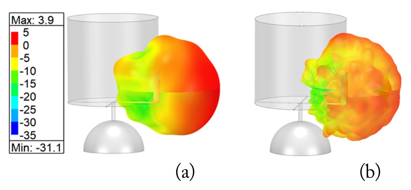
Simulated 3-D radiation pattern of the proposed antenna with a lamp: (a) 2.45 GHz, (b) 6.5 GHz.
Table 2 shows the performance comparison of the planar and flexible conditions of the proposed antenna. The lamp is made of nylon and affects the radiated efficiency of the antenna due to the interaction of the radiation field with the material. However, the thickness of the nylon is relatively thin since it is not significantly affected when compared to the bend on foam. These results show that the proposed antenna has acceptable performance and has the potential to be used in flexible IoT applications.

Performance comparison of the planar and flexible conditions of the proposed antenna.
Table 3 provides a performance comparison between the proposed antenna and existing state-of-the-art T&F patch antenna structures. From this comparison, the proposed antenna was optimized for gain and efficiency compared to previous reports. In addition, the possibility of integrating antennas into glass, plastic, wood, or other common home surfaces is also examined in terms of IoT applications. This problem will be carefully investigated in future work.

Performance comparison between the proposed antenna and existing T&F patch antenna structures.
V. Conclusion
In this article, a dual-band T&F patch antenna for the next generation of Wi-Fi technology applications, including the 2.4–2.5 GHz and 5.925–7.125 GHz (Wi-Fi 6E) bands, is presented for the first time. The proposed antenna is based on a transparent conductor film and a PVC substrate, which are known for their flexibility, low dielectric loss, and mechanical robustness. The antenna was carefully studied under planar and bending conditions to confirm its feasibility for use in flexible antenna applications. The AUT results of the bending analysis demonstrated that the performance slightly decreased compared to the same analysis under planar conditions because of bending. In addition, when increasing the extent of bending, the reflection coefficients tended to move slightly to the right side. Meanwhile, the reflection coefficients maintained good impedance matching when changing the bending and substrates (i.e., from foam to lamp). These results show that the proposed antenna can be a potential candidate for the integration and connection of wireless devices with high aesthetic antennas for use in smart-home applications.
Acknowledgments
This study was supported by the National Research Foundation of Korea funded by the Korean Government under Grant 2016R1D1A1B02012957.
References
Biography

Tien Dat Nguyen received his B.S. degree in electrical and electronics engineering from the Hanoi University of Science & Technology (HUST), Ha Noi City, Viet Nam, in 2020 and his M.S. degree from the Department of Graduate School of Nano IT Design Fusion at Seoul National University of Science and Technology, Seoul, South Korea. He is currently pursuing a Ph.D. degree with Department of Semiconductor Engineering at Seoul National University of Science and Technology, Seoul, South Korea. His research interests include EMI/EMC, RF filter, frequency selective surface (FSS) and transparent antennas.

YongKeun Lee (Member, IEEE) received his B.S. degree in material engineering from Iowa State University, Ames, IA, USA, in 1991, his M.S. degree in material science from Columbia University, New York City, NY, USA, in 1993, and his Ph.D. degree in materials engineering from the Rensselaer Polytechnic Institute, Troy, NY, USA, in 1996.
He was an Assistant Professor with the Nanyang Technological University, Singapore, and was a Principal Engineer with Samsung Electronics LCD Business, Giheung, South Korea. Since 2007, he has been the Dean of the Graduate School of Nano IT Design Fusion, Seoul National University of Science and Technology, Seoul, South Korea, where he is currently a Professor of the Nano IT Fusion Program.

Chang Won Jung (S’02-M’06) received his B.S. degree in radio science and engineering from Kwangwoon University, Seoul, South Korea, in 1997, his M.S. degree in electrical engineering from the University of Southern California, Los Angeles, CA, USA, in 2001, and his Ph.D. degree in electrical engineering and computer science from the University of California at Irvine, Irvine, CA, USA, in 2005.
He was a Research Engineer with the Wireless Communication Department, LG Information and Telecommunication, Seoul, South Korea, from 1997 to 1999. From 2005 to 2008, he was a Senior Research Engineer with the Communication Laboratory, Samsung Advanced Institute of Technology, Suwon, South Korea. Since 2008, he has been a Professor with the Graduate School of Nano-IT Design Technology, Seoul National University of Science and Technology, Seoul, Korea. He has authored over 120 papers in refereed journals and conference proceedings, one book, and more than 50 international patents. His current research interests include antennas for multi-mode multi-band communication systems, multifunctional reconfigurable antennas, electromagnetic interference/electromagnetic compatibility, millimeter-wave applications, and wireless power transfers for energy harvesting.