Gain and Frequency-Selectivity Enhancement of Dual-Polarized Filtering IBFD Antenna Using PRS
Article information
Abstract
A dual-polarized filtering Fabry–Perot antenna (FPA) with high selectivity and high isolation is proposed for in-band full-duplex (IBFD) applications. The proposed antenna utilizes a square patch as the feeding element, which is fed by a double differential-fed scheme for dual-polarized radiation with high isolation. The patch is loaded with a symmetrical cross-slot and four shorting pins for a broad passband filtering feature. To enhance broadside gain across a wide frequency range, the patch is incorporated with a partially reflecting surface (PRS), which is composed of two complementary cross-slot and patch arrays. Moreover, the frequency selectivity of PRS is exploited to improve the filtering characteristic. The double differential feeds are realized based on out-of-phase power dividers, which are combined with simple low-pass filters to further improve the out-of-band suppression. The final design was fabricated and measured. The measurement results show excellent results with a 10-dB return loss bandwidth of 21.5% (4.91–6.09 GHz), isolation of greater than 40 dB, peak gain of 13.7 dBi, out-of-band suppression level of better than 27 dB, and a cross-polarization level of less than −27 dB.
I. Introduction
Recently, dual-polarized antennas have regained significant interest from antenna researchers with the aim of achieving extremely high isolation. This high isolation (more than 40 dB), if achieved, will greatly assist in the interference reduction between the transmitter and receiver, which enables in-band full-duplex (IBFD) technology where the spectral efficiency can be doubled [1]. Obtaining this required high isolation is challenging. While several unconventional or specialized techniques, such as wavetraps [2], couplers [3], auxiliary ports [4], and decoupling structures [5], have been proposed, the mainstream method is still the use of differential-fed schemes [6–10]. This is not a surprising trend since differential feeds provide a simple means to cancel out the coupling. The basic configuration of this antenna type, which could consist of either single or double differential feeds, is illustrated in Figure 1. For the schematic in Figure 1(a), using the differential-fed scheme for Ports 2+ and 2−, named Port d, its S-parameters are calculated as follows [10]:
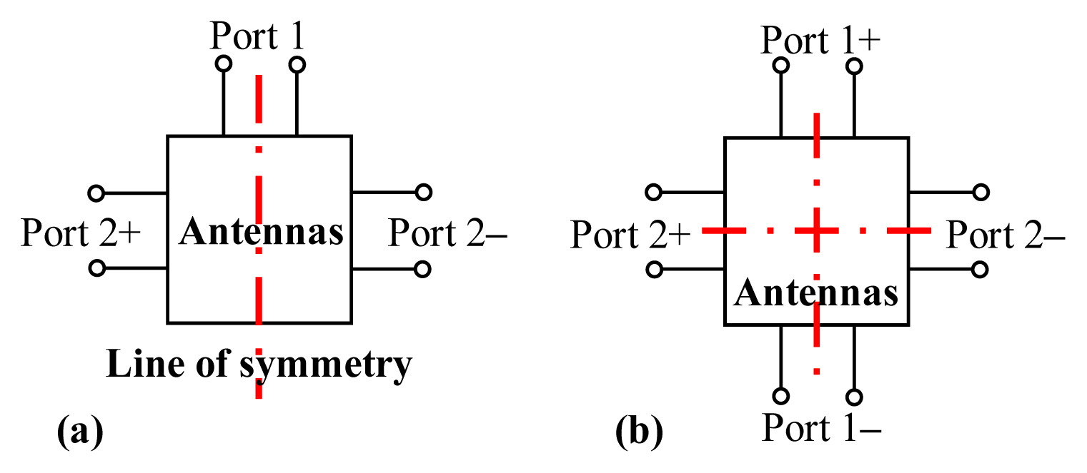
Schematic of the dual-polarized IBFD antenna using (a) single and (b) double differential-fed schemes
To obtain an infinite isolation (S1d = 0), the antenna needs to be perfectly symmetrical across Ports 2+ and 2−, that is, S2+1 = S2-1. For the double differential-fed antenna shown in Figure 1(b), the isolation among differential ports is calculated as follows:
In this case, the antenna needs to be perfectly symmetrical across two planes: S2+1+ = S2+1−, and S2–1− = S2–1+. As clearly seen in (1b) and (2), differential feeds and symmetry can be utilized together to achieve theoretically infinite isolation.
Due to the fast-increasing requirements of wireless communication systems, multifunctional antennas have become more demanding. Filtering antennas [11], which realize both antennas and filter functions in a single structure, have been considered a powerful solution for reducing the losses, size, and cost in a wireless communication system. Thus, it is expected that many differential-fed dual-polarized filtering antennas [12–16] will be proposed. For filtering purposes, various approaches have been applied, including using multilayer structures, slots, and parasitic elements. To increase the gain, filtering elements are commonly arrayed, such as [15, 16]. This method increases complexity in both the antenna and feeding configurations.
This paper provides a new design for a differential-fed dual-polarized filtering antenna with a significant improvement in performance, in terms of isolation, gain, and filtering characteristics, compared to the literature. The high gain is achieved with a simple structure of the Fabry–Perot antenna (FPA), which is also optimized to enhance filtering performance. For feeding, a cross-slot and four shorting pins are inserted into a square patch to not only broaden the bandwidth but also achieve the filtering feature. Although there have been some existing dual-polarized FPAs, such as [17–21], their performances in terms of isolation and gain filtering are quite limited. This will be discussed in Section III.
II. Antenna Design
1. Antenna Configuration
Figure 2 shows an overview of the proposed FPA with detailed geometries of the feeding patch and the partial reflecting surface (PRS). The patch is built on the top side of Sub. 1, with dimensions of 70 × 70 mm2, which is suspended on the ground (GND) at an airgap of Ha. It is loaded with a modified cross-shaped slot and fourshorting pins to achieve a broad passband filtering characteristic. The Fabry–Perot cavity is formed by the PRS suspended over the GND at a height of Hc. The PRS consists of 9 × 9 unit-cells printed on Sub. 2. As shown in Figure 2(c), each PRS unit cell is a complementary structure with a cross-slot on the bottom side and a plus-shaped patch on the top side, which allows broadband operation. Roger RT/Duroid 5880 sheets (ɛr = 2.2 and tanδ = 0.0009) are chosen for Sub. 1 and Sub. 2. The FPA is characterized by using the ANSYS Electronics Desktop for broadband, dual-polarization, high-isolation, high-gain, and band-pass filtering at a center frequency of 5.5 GHz. In the simulations, the double differential feed is modeled using four single-ended ports (P1+, P1−, P2+, and P2−) with a characteristic impedance of 50-Ω [Fig. 2(a)]. Its optimized parameters are as follows: df = 5, dv = 0.51, s = 0.2, Ls1 = 5.4, Ls2 = 7, Ls3 = 1.75, dp = 17.4, Wp = 26, u1 = 12, v1 = 7, u2 = 10, v2 = 4, P = 13, h1 = h2 = 0.7874, Ha = 2.4, Hc = 28 (unit in mm).

Geometry of the proposed antenna: (a) side-view, (b) topview of the feed antenna, and (c) PRS unit-cell.
2. Properties of the PRS Structure
The bandwidth of the FPA is determined by the reflection phase of the PRS, while the directivity increment is related to the reflection magnitude of the PRS [20]. Accordingly, a complementary structure with cross-slots and plus-shaped patches is chosen for the PRS to allow broadband and high directivity. To illustrate this feature, the PRS unit cell is simulated with periodic boundary condition (PBC) and Flotquet ports, as shown in Figure 3(a). Its reflection properties are given in Figure 3(b), showing a positive-gradient reflection phase in the band ranging from 5.2 GHz to 5.8 GHz. In this range, the resonance condition of the FPA [17], [18], [20], and [21] is satisfied, resulting in a gain improvement across a wide bandwidth. It is noted that since the resonance condition does not satisfy the range of 5.2–5.8 GHz, the PRS will contribute to the filtering performance, as will be shown in the next section.
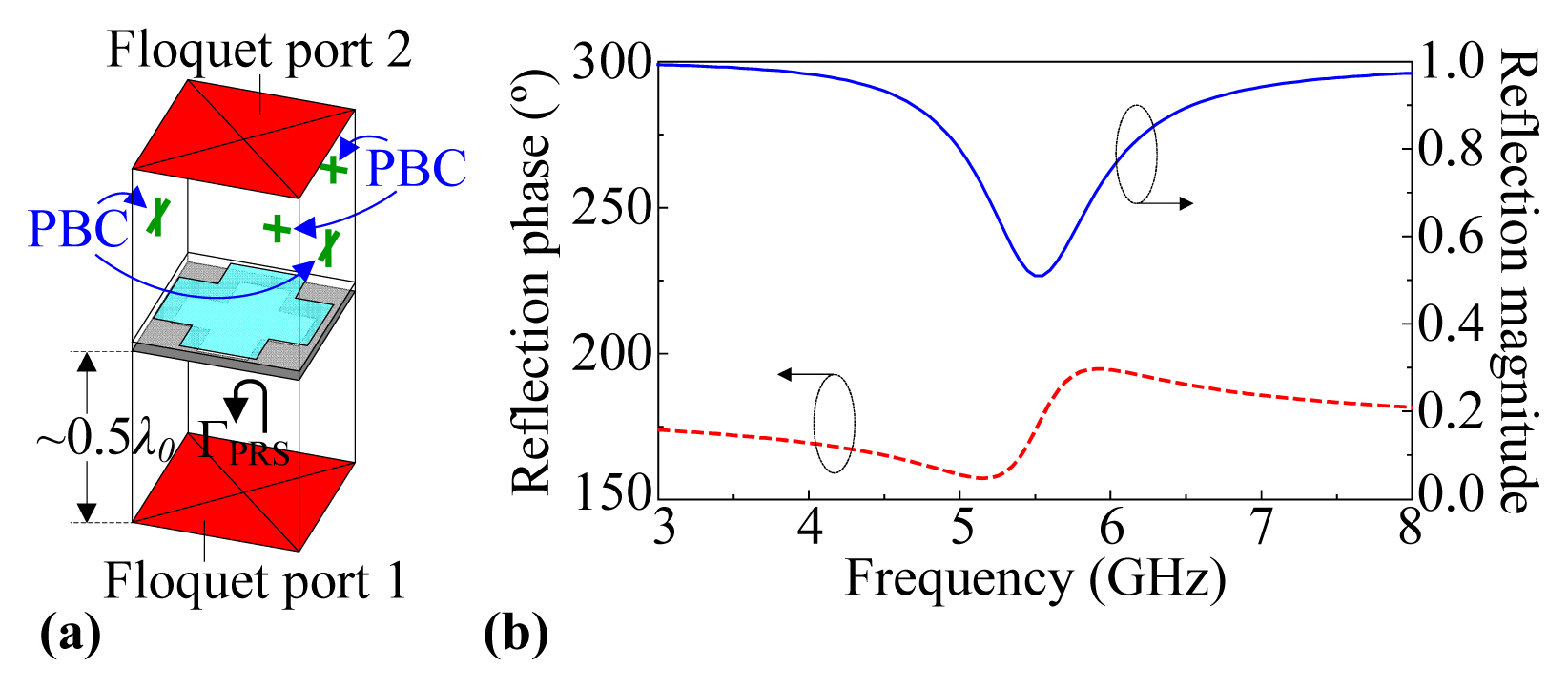
(a) PRS unit-cell modeling in the ANSYS Electronics Desktop and (b) its reflection characteristics.
3. Filtering Mechanism
To illustrate the working mechanism, we examine and compare the performances of the four configurations in Figure 4. It is noted that Ants. 1–3 are just patches alone while the proposed design includes Ant. 3 and the optimized PRS. For the sake of comparison, Ants. 1–3 have the same parameters as the proposed antenna. The S-parameters of the differential feed are calculated as in (1a). As shown in Figure 5(a), the conventional patch (Ant. 1) yields a narrow impedance bandwidth (i.e., 4.42–4.67 GHz [4.5%] for a −10-dB reflection coefficient) with only one resonance. The patch with a cross-slot generates extra resonance in the high-frequency region, that is, Ant. 2 achieves two resonances at 4.4 GHz and 6.0 GHz. To further investigate the radiation mechanism of Ant. 2, the surface current distributions are simulated at the two resonances, as shown in Figure 5(b). At the lower resonance frequency, the currents on the entire patch follow the fundamental TM10 mode of a conventional patch. At the higher resonance frequency, the dominant currents are on the cross-slot, which indicates that the extra resonance is caused by this slot. In Figure 5(a), by the insertion of the four shorting pins (Ant. 3), the dominant TM10 mode resonance is shifted toward the higher frequency, that is, around 5.2 GHz, while the slot-mode resonance hardly changed, that is, around 6 GHz. This is demonstrated by the current distributions of Ant. 3, as shown in Figure 5(c). Since Ants. 2 and 3 have not been fully optimized, their impedance matchings are not very good. By adding the PRS structure, the impedance matching is improved; that is, the proposed antenna achieves a bandwidth of 4.91–6.11 GHz (21.8%) for a −10-dB reflection coefficient. Due to the symmetric structure, the double differential-fed antennas theoretically achieve infinite isolation [see (2)]; therefore, Sdd21 is not shown here.
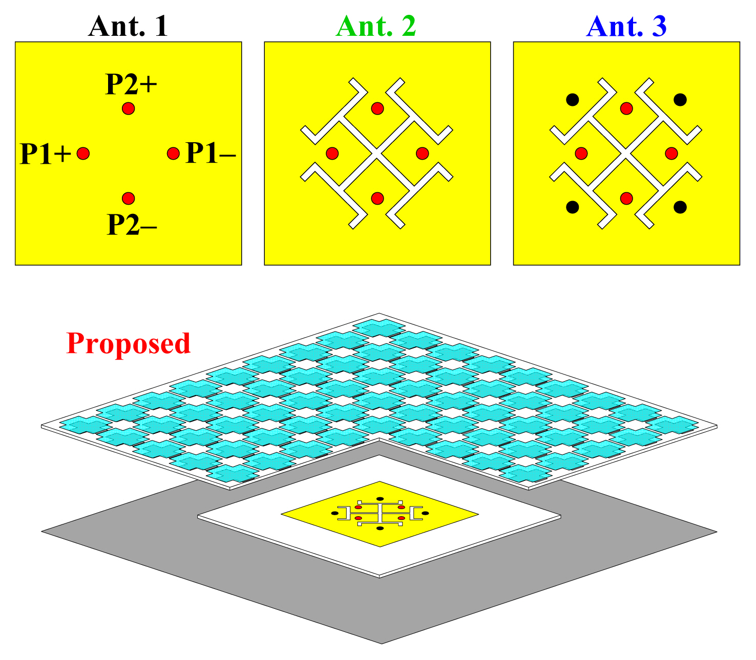
Design evolution of the proposed antenna. Ants. 1–3 are patches alone while the proposed design includes Ant. 3 and the wideband PRS.
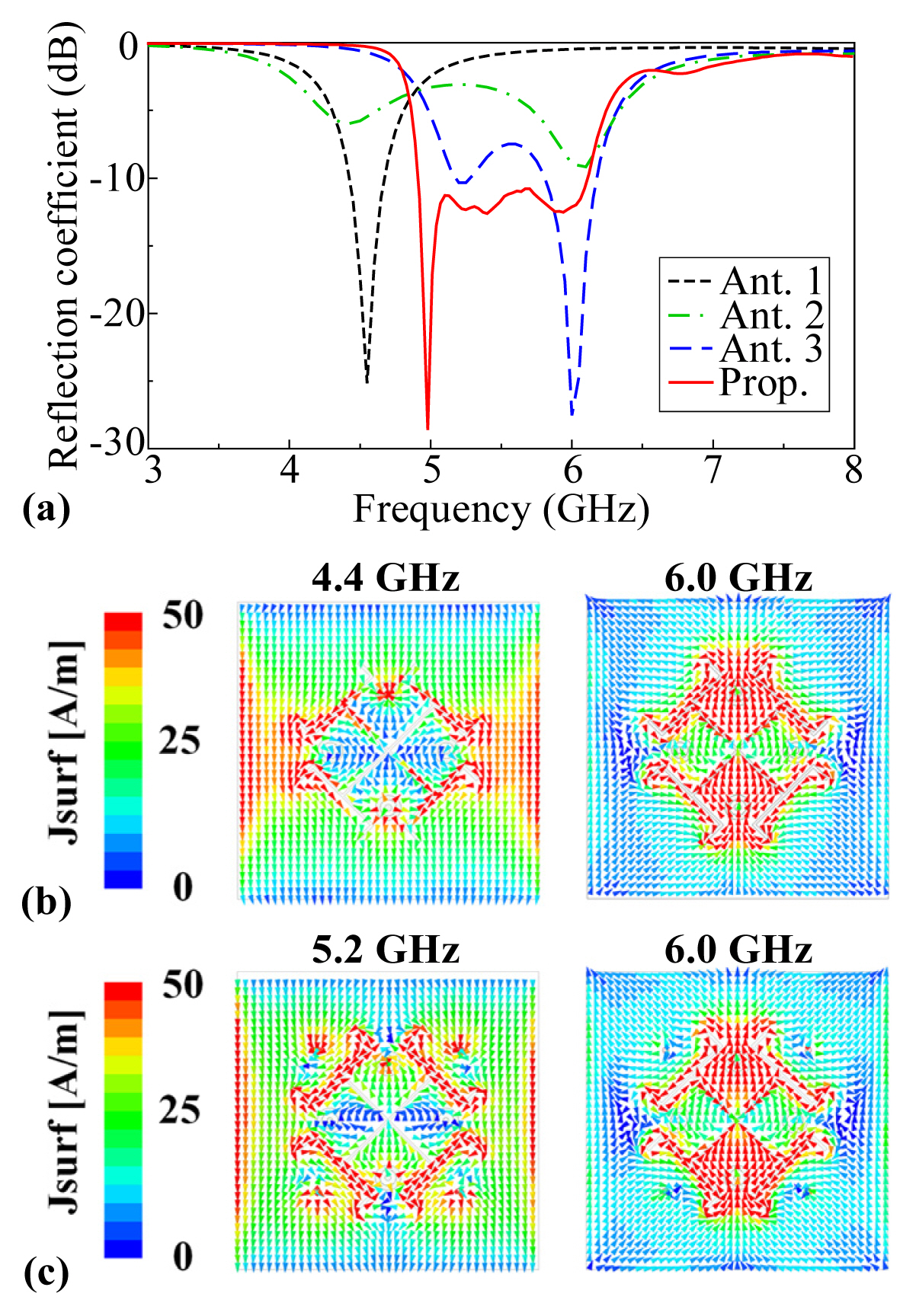
(a) Reflection coefficient of differential antennas; Current distributions on (b) Ant. 2, and (c) Ant. 3 at their resonant frequencies when the pair of P1+ and P1− are excited.
Figure 6 shows the broadside realized gains for the different configurations. The conventional patch (Ant. 1) suffers a narrow gain bandwidth with a peak value of 9.4 dBi and does not yield any out-of-band suppression. By adding cross-slot and shorting pins, the gain bandwidth is broadened in Ants. 2 and 3, which also exhibit out-of-band suppression, but their roll-off rates (RoRs) are not very sharp. In the proposed design, the presence of PRS enhances the broadside gain of ~5 dB and improves the filtering feature significantly; that is, its out-of-band suppression levels are 48 dB and 14 dB for the lower and upper stopbands, respectively.
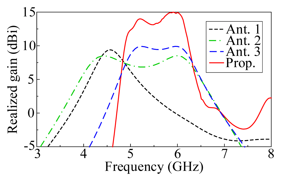
To further evaluate the filtering performance, the RoRs of the different antennas are calculated at the lower and upper band edges using the following equation [22]:
where f3dB denotes the frequency with 3-dB reduction in average realized gain and f20dB denotes the frequency where the average realized gain drops 20 dB. Ant. 2 yields an RoR of 8.3 and 8.0 dB/GHz at the lower and upper band edges, while the corresponding RoR values of Ant. 3 are 16.0 and 11.0 dB/GHz. The RoRs of the proposed design are 42.8 dB/GHz and 23.4 dB/GHz, which are significantly higher than those of the other designs.
4. Effects of the PRS Size
The PRS size needs to be large enough to provide sufficient gain enhancement. However, if it is too large, there can be a local minimum in gain due to the lower reflection coefficient of the PRS at the center frequency [Fig. 3(b)]. This is illustrated in Figure 7 (see the gain for 11×11-cell PRS). According to this result, the 9×9-cell configuration offers the smallest gain variation and the widest 3-dB gain bandwidth; therefore, it is chosen for the final design.
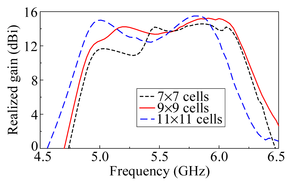
Broadside gain of the proposed FPA with different PRS sizes.
III. Realization and Measurement
1. Feeding Network
The double differential feeds of the proposed FPA are realized based on an out-of-phase power divider [23], as illustrated in Figure 8(a). Each differential feed consists of a Wilkinson power divider and a 180° phase shifter, which is compensated for by the Roger RO4003 substrate (ɛr = 3.38, tanδ = 0.0027, and thickness of 0.508 mm) and the center frequency of 5.5 GHz. To further improve the stopband in the high-frequency region, four simple low-pass filters (LPFs) with stepped impedance resonators [24] are added to the output microstrip lines. The positions of the LPFs should be optimized to ensure the symmetry of the structure. Due to the compact and simple configuration, the LPFs do not increase the complexity of the feeding network. The performances of the feeding network are shown in Figure 8(b). It is observed that the feeding network yields nearly perfect differential signals at the outputs and good LPF features with the cut-off frequency at 6.0 GHz. The reflection coefficients (|S11| and |S22|) are < −15 dB at 4.8–5.8 GHz. Within this frequency range, the divided powers at the outputs are nearly equal and phase differences are 180º ± 1.5º.
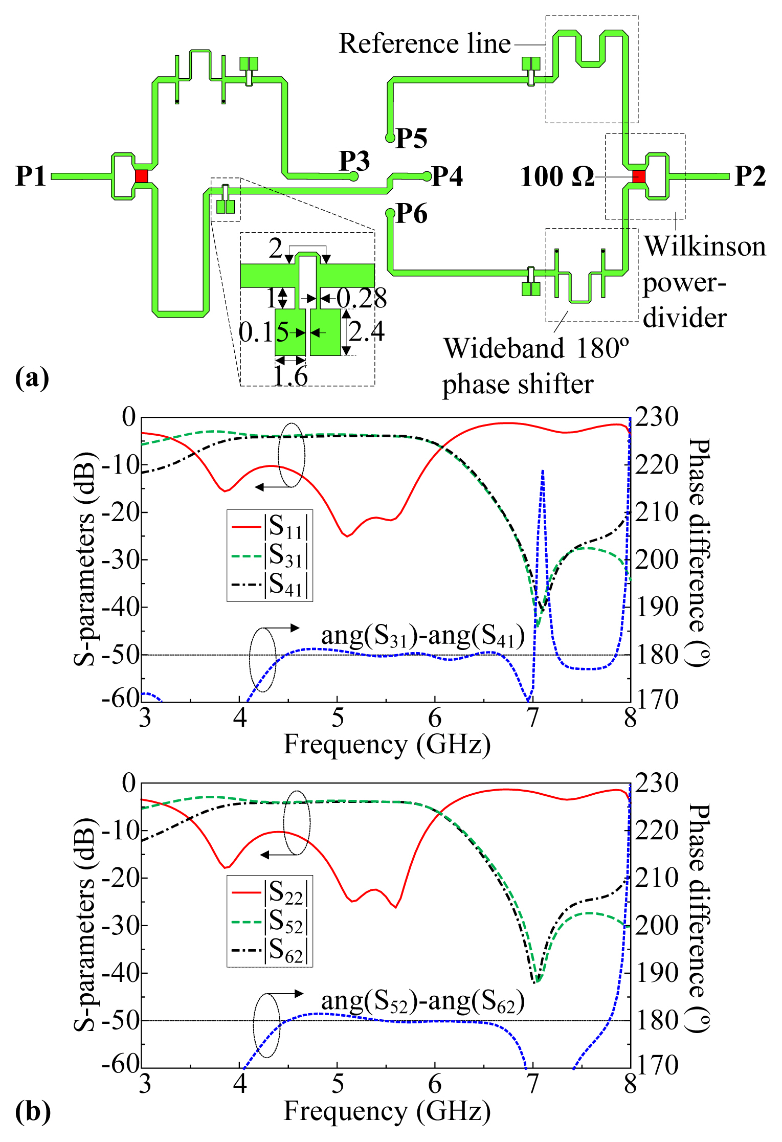
(a) Realization of differential-fed (units: mm) and (b) their performances.
2. Results
For verification, the final FPA, including the feeding network, is fabricated and measured. The feeding network, patch, and PRS are fabricated using printed circuit board (PCB) technology. Plastic posts and screws are used to construct the final prototype, as shown in Figure 9. The protype has an overall dimension of 120 × 120 × 29.3 mm3 (1.96λmin × 1.96λmin × 0.48λmin), where λmin is the free-space wavelength referring to the lowest operation frequency.
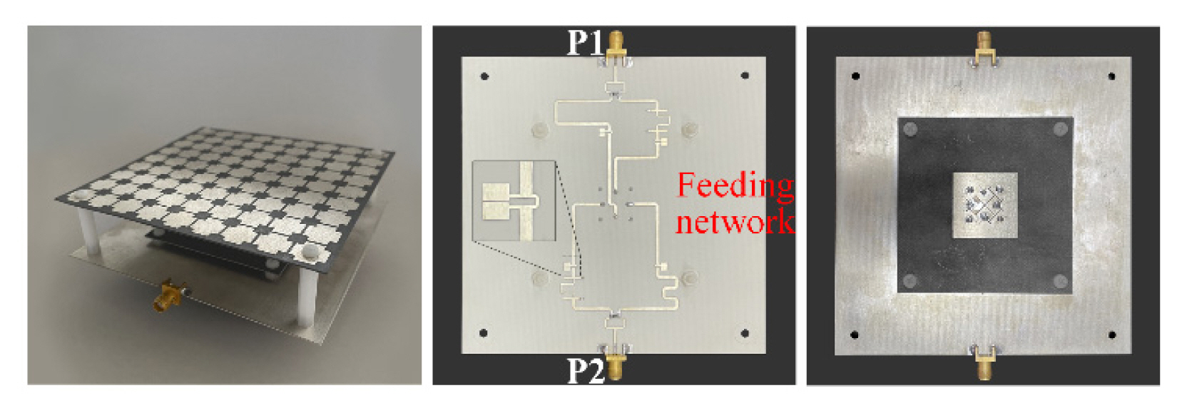
Fabricated prototype of the proposed antenna
Figure 10(a) illustrates the simulated and measured S-parameters of the antenna prototype. A good agreement between the simulation and measurement results is observed. The measurements show an overlapped bandwidth of 21.5% (4.91–6.09 GHz) for 10-dB return loss, whereas the simulated value is 20.9% (4.87–6.02 GHz). Also, across the impedance bandwidth, the measured isolation among two ports is better than 40 dB as compared with the simulated result of > 45 dB.
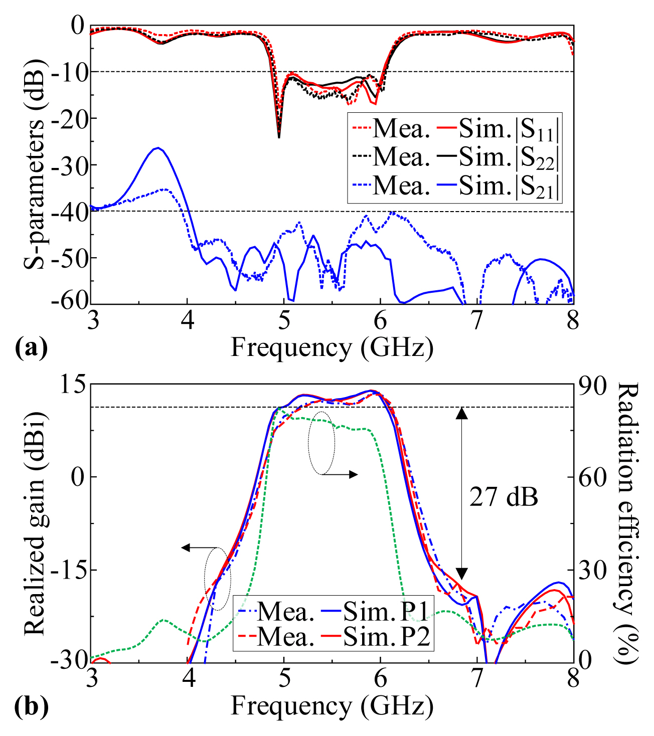
Simulation and measurement results of the antenna prototype: (a) S-parameters and (b) broadside realized gain
The realized gain of the antenna is shown in Figure 10(b). Again, the measurements agree well with the simulation, and both indicate that the proposed antenna yields high broadside gains and high frequency selectivity for the two ports. The measurements result in a 3-dB gain bandwidth of 18% (5.11–6.12 GHz), with a peak value of 13.7 dBi, whereas the simulated 3-dB gain bandwidth is 20.5% (4.94–6.07 GHz), with a peak value of 13.9 dBi. Moreover, both simulation and measurement indicate that the antenna yields a good band-pass filter function; that is, its out-of-band suppression is ≥ 27 dB. Due to the limitations of the chamber, the measured radiation efficiency (RE) is not available. Nevertheless, the simulated RE is better than 75% within the passband. Good agreement between the measured and the simulated gains also indicates an actual RE of around this value.
Figures 11 and 12 illustrate the normalized radiation patterns of the antenna prototype when ports 1 and 2 are excited, respectively. Both the measurement and the simulation indicate that the proposed FPA achieves excellent dual-polarized radiation. The measured cross-polarization levels are higher than the simulation values, which are attributed to realization tolerance, the effects of the tapers and racking in the far-field measurement setup, and the quality of the chamber. Nevertheless, the measurements result in a cross-polarization level <−27 dB, side-lobe level <−18 dB, and front-to-back ratio (F-B) > 25 dB.
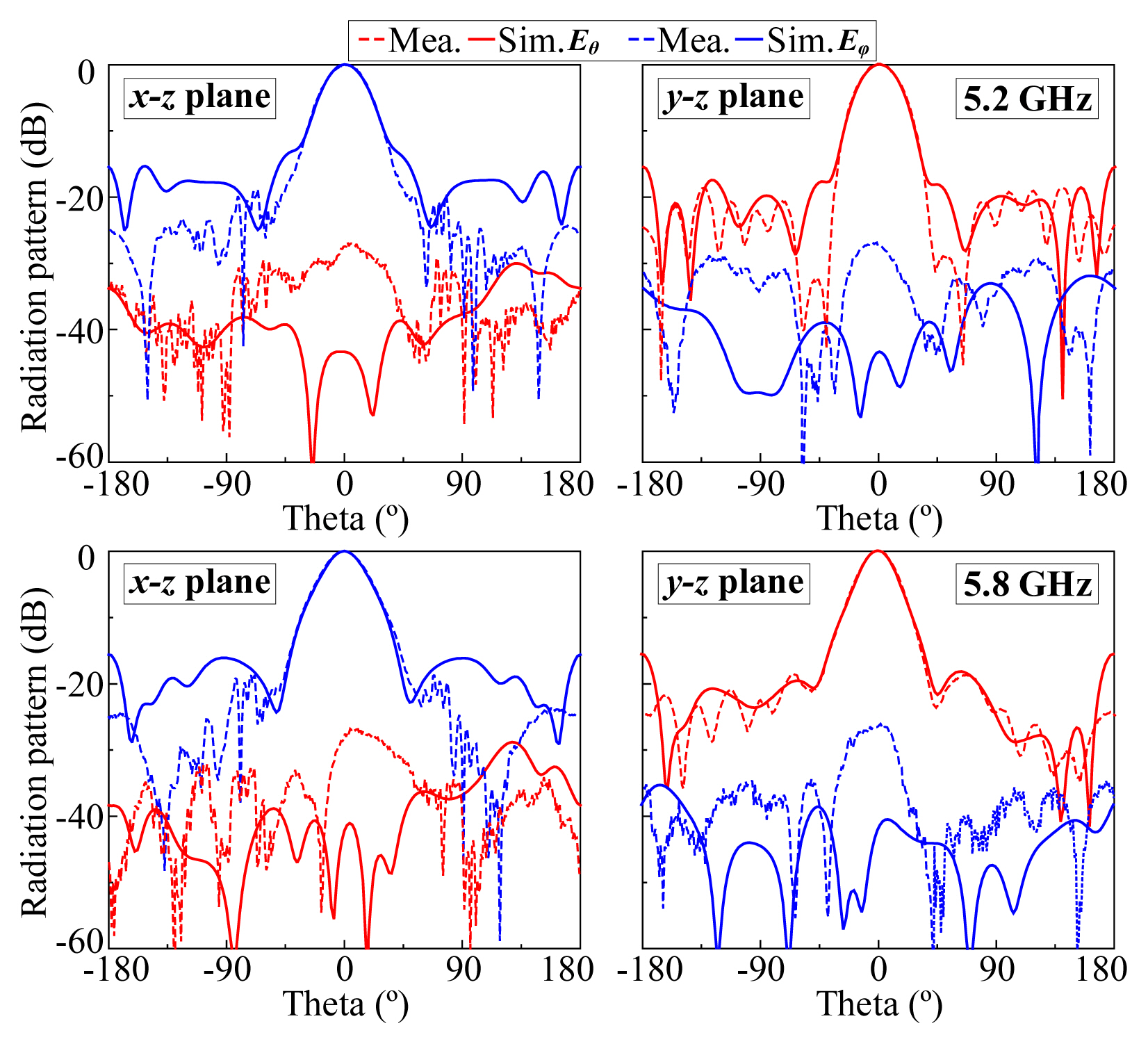
Radiation patterns of the FPA prototype when the Port 1 is excited

Radiation patterns of the FPA prototype when Port 2 is excited
3. Comparison
A comparison between the proposed design and the reference antennas is made in Table 1. Compared with previous differential- fed dual-polarized filtering antenna arrays [15, 16], this work offers a simpler configuration, higher isolation, and a higher out-of-band suppression level. Relative to dual-polarized FPAs [17–19], the proposed antenna yields the advantages of a small size, wider bandwidth, and higher isolation, and especially, a passband filtering feature. Compared with the recent filtering FPA [21], thanks to the patch with slot and shorting pins and the filtering feeding network, the proposed FPA achieves a much better filtering characteristic, that is, a higher out-of-band suppression level, sharper RoR, and higher gain.

Comparison of the proposed antenna and recent related works
IV. Conclusion
A dual-polarized filtering antenna with high-gain and high-frequency selectivity has been described. The proposed design takes advantage of a double differential-fed patch antenna with an etched cross-slot and is loaded with shorting pins to realize broadband operation and filtering features. To enhance the broadside gain and frequency selectivity, the patch is incorporated with the broadband PRS structure. Two out-of-phase power dividers are integrated with simple LPFs to realize double differential feeds and further improve suppression at high frequency. The final prototype with an overall size of 1.96λmin × 1.96λmin × 0.48λmin achieves a 10-dB return loss bandwidth of 21.5% (4.91–6.09 GHz), an isolation of ≥ 40 dB, a 3-dB gain bandwidth of 5.11–6.12 GHz, a peak gain of 13.7 dBi, a cross-polarization level of ≤ −27 dB, and an out-of-band suppression level of ≥ 27 dB. These features make the proposed FPA a good candidate for IBFD applications as well as other wireless communication systems.
Acknowledgments
This research is funded by the Vietnam National Foundation for Science and Technology Development (NAFOSTED) under grant number 102.04-2021.06.
References
Biography

Ngoc Tien Le received a B.Sc. (Eng.) in electronics and telecommunication from Hanoi University of Science and Technology, Hanoi, Vietnam, in 2021, where he is currently pursuing a master’s degree in the electromagnetic field and microwave technology at the Communication R&D Laboratory. His research interests include microstrip patch antennas, Fabry–Perot antennas, and in-band full-duplex antennas.

Truong Le-Huu received an engineering degree in electronics and telecommunications from Hanoi University of Science and Technology, Vietnam, in July 2006, and a Master of Engineering degree in electronic engineering from Dongguk University, Korea, in February 2009. From March 2009 to November 2018, he worked for the Viettel Group, where he was appointed Vice Director of Engineering of Radar Institute in 2012. From November 2018 to April 2021, he worked as a technical sales engineer for Richardson RFPD Inc., and he became a Ph.D. candidate in June 2020 at Hanoi University of Science and Technology. Since April 2021, he has been Director of the Electronic Platform Center, Viettel Aerospace Institute, Viettel Group. His research interests include antennas, RF transceivers, RF power amplifier systems, radar, and electronic warfare.

An Ngoc Nguyen was born in Hanoi, Vietnam, in December 1988. He received a B.E. in telecommunication engineering from Hanoi University of Science and Technology in 2011 and an M.E. and a Ph.D. in electrical, electronic and communication engineering from Chuo University, Japan, in 2014 and 2017, respectively. Since April 2017, he has been with the University of Engineering and Technology-VNU, Hanoi, where he is currently a Lecturer. His current research interests include smart sensors, antennas, and material characterization using free-space techniques.

Son Xuat Ta received a B.Sc. (Eng.) in electronics and telecommunications from Hanoi University of Science and Technology, Vietnam, in August 2008 and received a Ph.D. in electrical engineering from Ajou University, Korea, in February 2016. From March 2016 to February 2017, he was a postdoctoral research fellow in the Department of Electrical and Computer Engineering, Ajou University. From March 2017 to August 2017, he was with the Division of Computational Physics, Institute for Computational Science, and the Faculty of Electrical and Electronics Engineering, Ton Duc Thang University, Ho Chi Minh City, Vietnam. From September 2017 to the present, he works as a Lecturer at the School of Electronics and Telecommunication, Hanoi University of Science and Technology, Vietnam. His research interests include electromagnetic, antennas, metamaterials, metasurfaces, metamaterial-based antennas, metasurface-inspired antennas, multiple polarized antennas, and millimeter-wave antennas. He has authored and coauthored over 100 technical journal and conference papers. He has served as a reviewer for over 15 scientific journals. He has been selected as a Top Reviewer for IEEE TRANSACTIONS ON ANTENNAS AND PROPAGATION in 2020 and 2021.

Khac Kiem Nguyen was born in Hanoi, Vietnam, in 1978. He received a B. Eng., M.Sc., and Ph.D. in 2001, 2003, and 2017, respectively, from the School of Electronics and Telecommunication (SET), Hanoi University of Science and Technology (HUST), Vietnam. From 2001 to now, he has worked as a Lecturer at SET, HUST, and Researcher at CRD LAB, HUST. His research interests include the design of microstrip antennas for next-generation mobile communication systems as well as passive RF components.

Nghia Nguyen-Trong (Member, IEEE) (Member, IEEE) received a Ph.D. (doctoral research medal) in electrical engineering from The University of Adelaide, Adelaide, SA, Australia, in 2017.
He is currently a Lecturer at The University of Adelaide. His main research interests include microwave circuits, advanced materials, absorbers, and various types of antennas.
Dr. Nguyen-Trong was one of the recipients of the Best Student Paper Award at the 2014 IWAT, the 2015 IEEE MTT-S NEMO, and the 2017 ASA Conferences and the Best Paper Award at the 2018 and 2020 AMS Conference. He has been continuously selected as a Top Reviewer for IEEE Transactions on Antennas and Propagation in 2018, 2019, 2020, and 2021, and IEEE Antenna Wireless and Propagation Letters in 2018 and 2021. He serves as a Technical Co-chair for the 2020 Australian Microwave Symposium (AMS) and 2022 IEEE International Symposium on Antennas and Propagation. He was listed among Australia’s Top 40 Early Career Researchers by The Australian in November 2021.