I. Introduction
Due to fast-growing wireless communication technologies, fifth-generation (5G) mobile communication systems have been widely rolled out and used in several different applications in recent times. Compared to 4G systems, 5G promises to provide seamless connectivity with higher data rates and lower latency [1]. Two main frequency groups have been adopted in this context—sub-6 GHz and millimeter-wave (mm-wave) bands. Due to their longer wavelength, sub-6 GHz bands have stronger penetration and travel longer distances; as a result, they receive a lot of attention in relation to 5G communication systems.
The ever-increasing data capacity requirements and miniaturization trend of wireless communication devices pose a significant challenge to antenna design in terms of achieving a compact size with high data rate handling capability. An effective way to solve this problem is to adopt multiple-input-multiple-output (MIMO) antenna technology, which improves both spectrum efficiency and data rates [2–4].
For the successful implementation of spatial diversity in a MIMO antenna system, strategies to decrease mutual coupling and improve isolation between the antenna elements are crucial. Many studies have focused on enhancing the isolation of MIMO antennas. Some MIMO antennas achieve good isolation by maintaining an appropriate distance between the antenna elements. In one study [5], mirror-imaged placement of the antenna elements and insertion of a chip inductor between closely spaced antennas were able to improve isolation. Apart from this, grounding branches can generate new coupling and affect isolation [6, 7]. The application of grounded branches can improve isolation in the lower frequency band and provide better impedance matching for the antenna [6]. Furthermore, a neutral line is often employed to weaken mutual coupling [8–10]. Connecting adjacent orthogonal pairs of antennas with a short neutral line leads to high isolation [10].
Additionally, defected ground structures (DGS) can improve isolation by affecting the circuit substrate’s effective dielectric constant distribution—this has become a commonly used technology for overcoming undesired coupling in MIMO antenna designs [11–14]. Some MIMO antennas use unique decoupling structures to improve isolation, such as the multi-slot decoupling structure [15], the generic decoupling structure composed of an array of H-shaped parasitic structures [16], and the rectangular microstrip stub [17].
Meanwhile, the antenna proposed in another study [18] used ungrounded full-wavelength strip resonators, which effectively enhanced the isolation between the antenna elements at the cost of reducing the impedance bandwidth. Meta-surface [19, 20] and electromagnetic band gap (EBG) structures [21–23] are also effective methods for improving isolation, although they are too complex to be used in miniaturized antennas. To sum up, the design methodology for achieving good isolation in a small-size MIMO antenna system continues to be a critical issue.
This paper presents a novel decoupling structure that utilizes a DGS to achieve high isolation of more than 23 dB. The DGS includes a rectangular slot with 42 circular slots located on each side. The antenna has a compact size of 28 mm × 28 mm × 0.8 mm, which is suitable for the miniaturization of sub-6 GHz 5G terminals. The proposed MIMO antenna covers both the 3.5 GHz (3.4–3.6 GHz) and 4.9 GHz (4.8–5.0 GHz) frequency bands. Furthermore, the measured total efficiencies at 3.5 GHz and 4.9 GHz are 76.65% and 71.93%, respectively. The calculated envelope correlation coefficients (ECC) is less than 0.00328 in both the desired frequency bands. Moreover, the simulated specific absorption ratio (SAR) values are all observed to be less than 1.4 in the dual bands, thus conforming to the standard for terminal equipment.
II. Antenna Structure
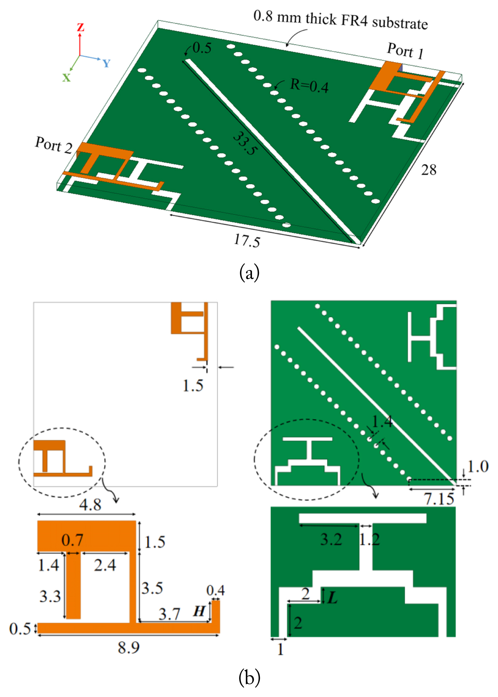
The configuration of the proposed antenna is illustrated in Fig. 1. The antenna elements are etched on an FR4 substrate with ɛr = 4.4 and tanδ = 0.02, with the size of the substrate being 28 mm × 28 mm × 0.8 mm. The antenna element comprises an inverted L-shaped radiation strip and an F-shaped feeding strip. These two antenna elements are distributed diagonally symmetric to the substrate. Furthermore, each antenna element is fed with a 50-Ω microstrip feedline. The DGS contributes to weakening mutual coupling and enhancing isolation. The detailed dimensions of the antenna element are illustrated in Fig. 1(b).
III. Antenna Analysis
1. Design Evolution
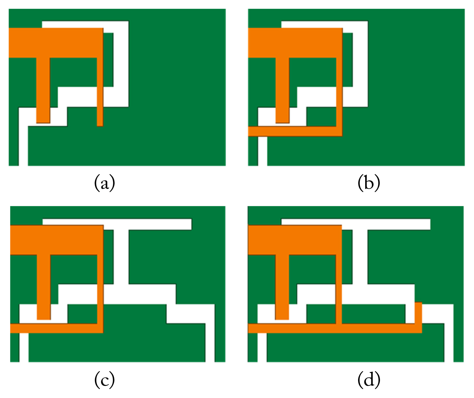
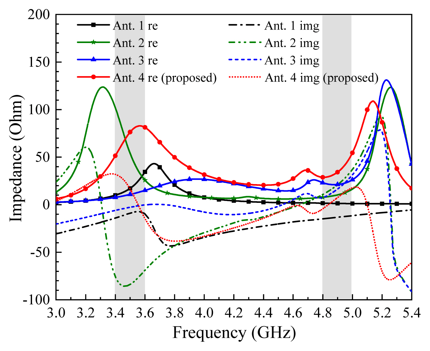
Fig. 2 depicts the methodology for the design evolution of a single MIMO antenna element. As shown in Fig. 3, the F-shaped structure of Ant-1 generates resonance in the lower frequency band. Ant-2, which is obtained by adding a rectangular patch to Ant-1, can excite two modified resonate modes. Meanwhile, Ant-3 modifies the etched slots of the ground plane and generates a symmetrical ground slot structure, which can change the antenna element’s distribution parameters—reducing its distributed capacitance and resistance. Therefore, although Ant-3 enhances the resonance of the two bands, it has a negative effect on impedance matching. In Ant-4, however, the addition of the inverted L-shaped radiation strip improves the performance, enabling it to achieve qualified performance in both the desired frequency bands, which are 3.4–3.6 GHz and 4.8–5 GHz. The impedance of the different antenna structures, as shown in Fig. 4, shows the L-shaped radiation strip of Ant-4 increases resistance and achieves better impedance matching within the desired frequency bands.
2. Dimension Optimization
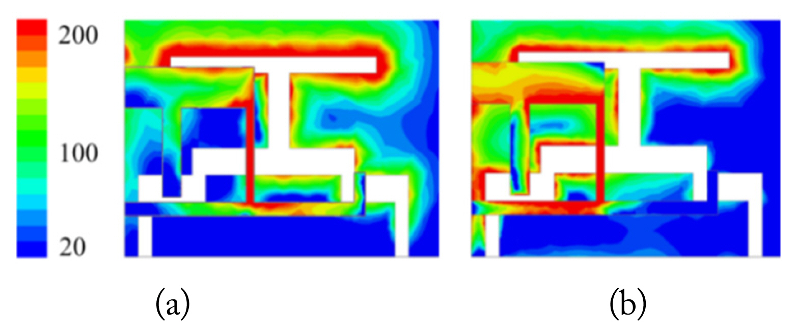
The surface current distributions of a single antenna element are depicted in Fig. 5. The surface current of 3.5 GHz is concentrated on the L-shaped radiation strip; hence, the resonance of the 3.5 GHz band can be effectively adjusted by changing the length of the L-shaped radiation strip. Meanwhile, Fig. 5(b) depicts that the current at 4.9 GHz is concentrated on the F-shaped feed strip and its corresponding ground slot structure. Therefore, modifying the structure of the slot at the corresponding position can significantly affect the performance of the antenna in the higher frequency band.
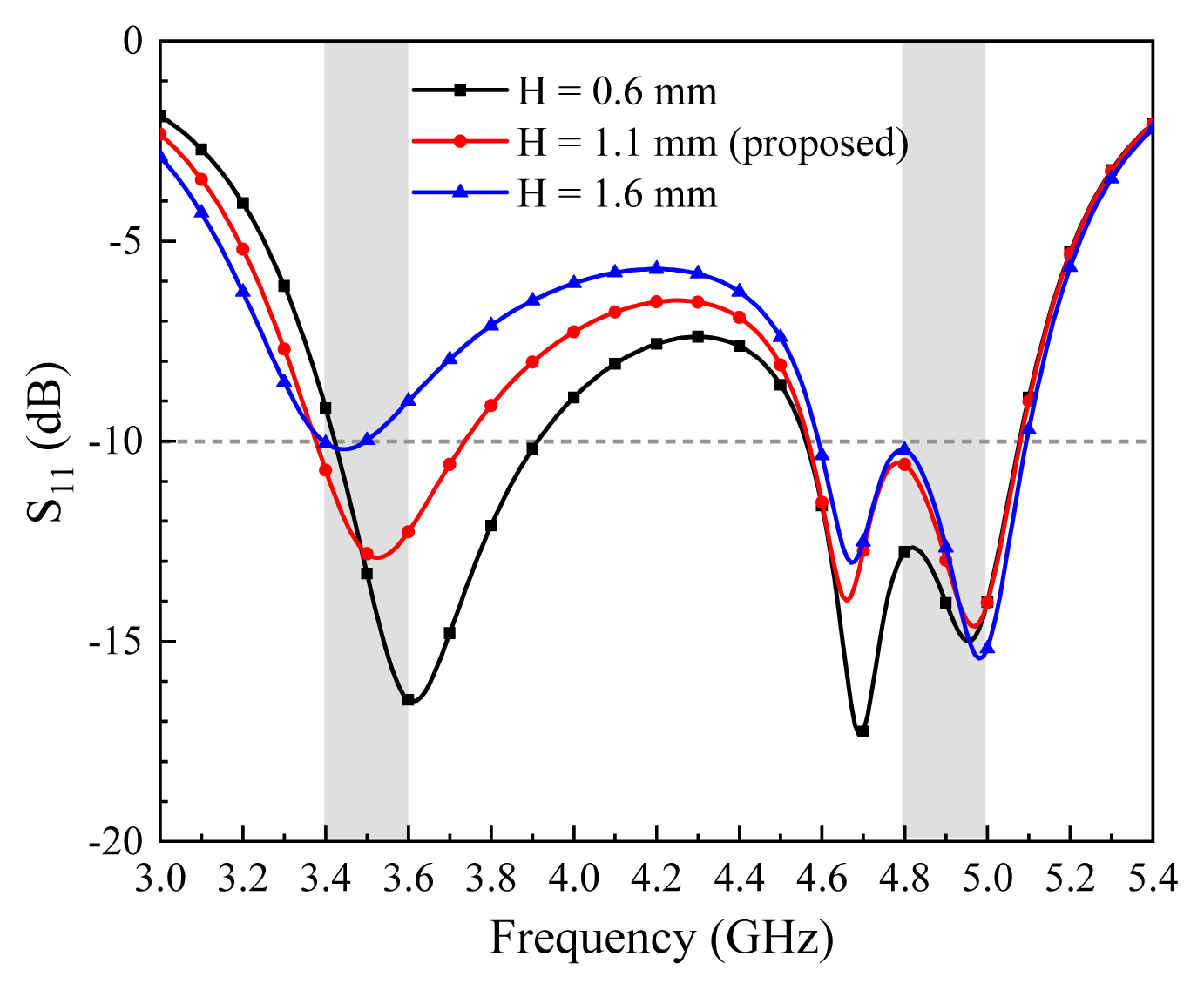
The simulated S11 parameters of different values of H and L (as shown in Fig. 1) are depicted in Figs. 6 and 7—verifying the above analysis derived from the surface current distributions. By increasing the length H of the L-shaped radiation strip, the lower resonant frequency of the antenna can be moved to higher frequencies. Meanwhile, when adjusting the value of L, the distribution parameters of the antenna elements will also change accordingly, effectively widening the operating band in the 4.9 GHz band. It is evident that when L = 1.0 mm and H = 1.1 mm, the desired frequency bands will be sufficiently covered.
3. Isolation Optimization
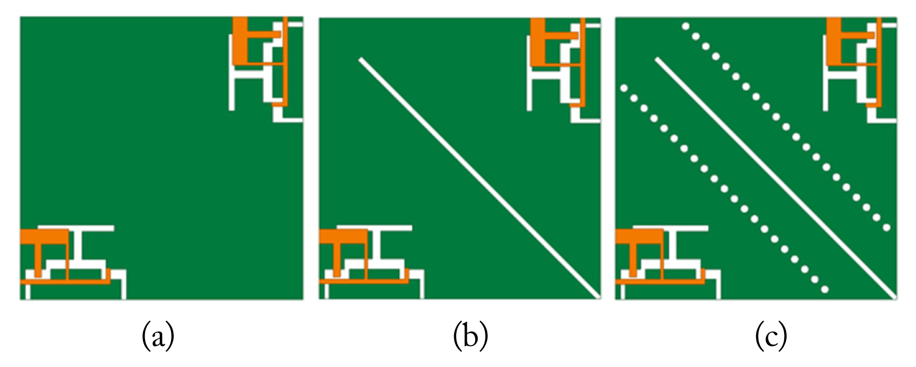
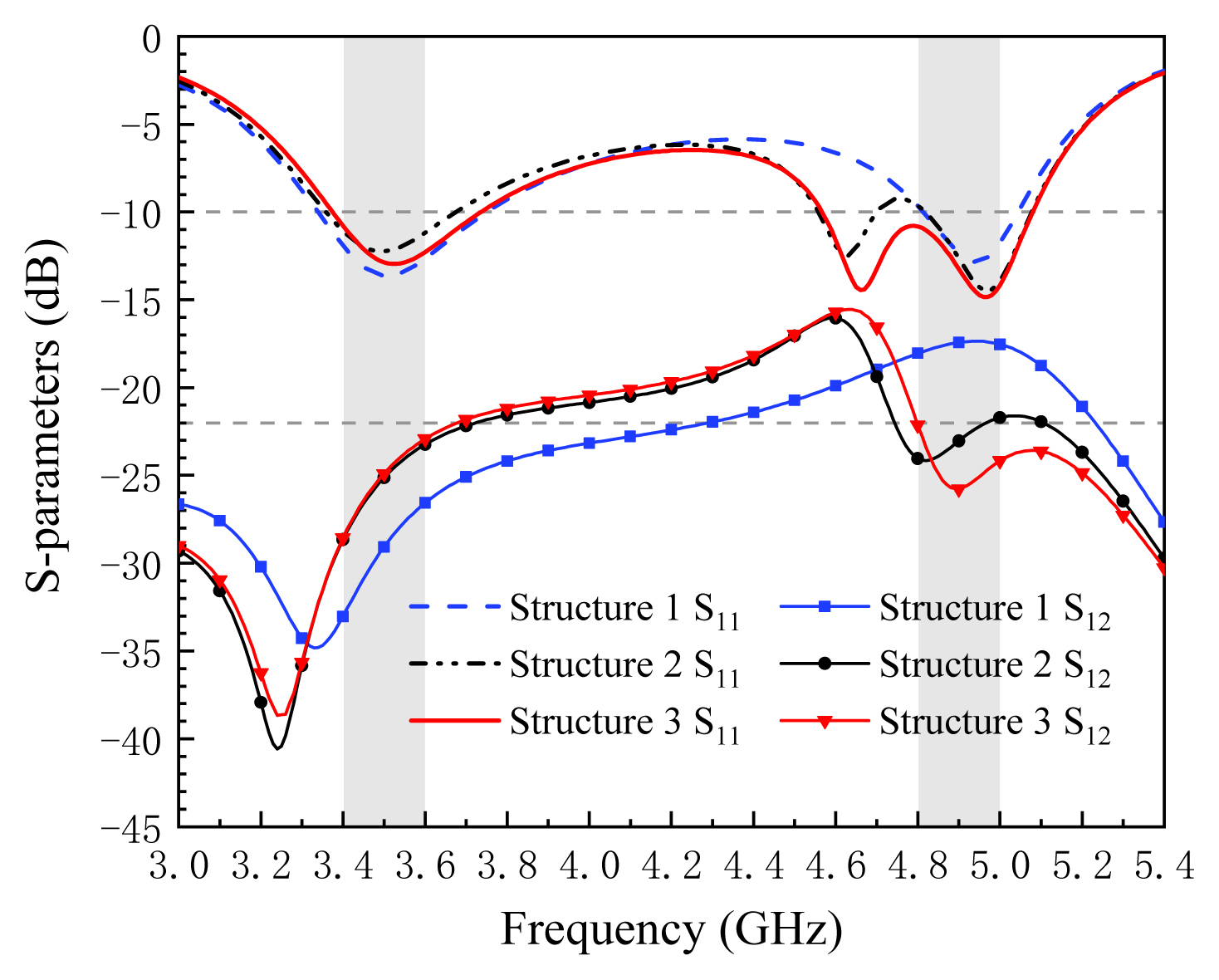
As depicted in Fig. 8, this study proposes different isolation structures—Structure 1, Structure 2, and Structure 3—to achieve better isolation performance. Compared to Structure 1, Structure 2 adds a diagonal rectangular slot, which improves antenna isolation to be more than −20 at the higher frequency band. Twenty-one circular slots are evenly distributed on both sides of the diagonal rectangular slot in Structure 3. The circular slots in the ground can improve high-frequency isolation while also broadening the bandwidth of the antenna in the higher frequency band. The slotted-dot lines broaden the −10 dB band-width from 4.8–5.07 GHz to 4.57–5.07 GHz, enabling the antenna to exhibit a more stable performance in the required 4.8–5.0 GHz band. The simulated S-parameters of the three isolation structures are shown in Fig. 9. Notably, the isolation of the proposed antenna is more than 22 dB in both the desired frequency bands.
4. 3D Radiation Pattern
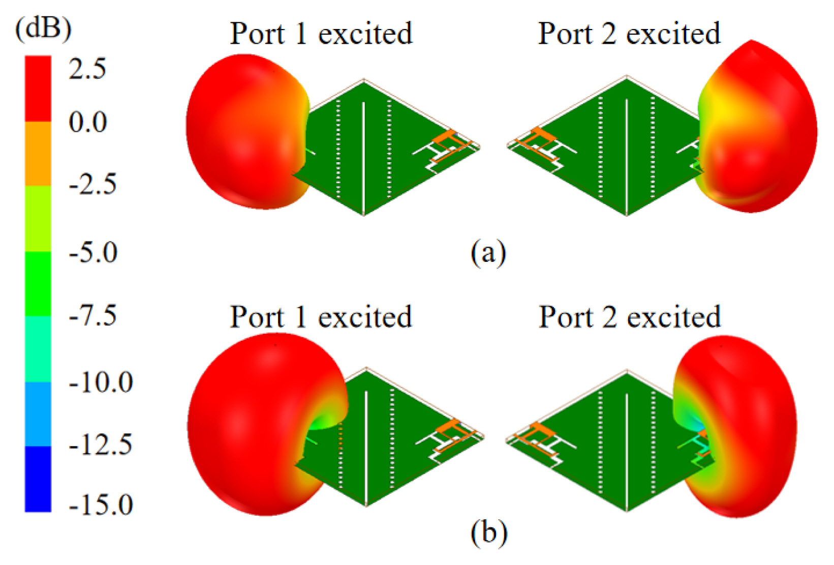
Fig. 10 presents the 3D radiation pattern of a single antenna element by inducing excitation at one port while keeping the other port terminated using a matching load. The simulated 3D radiation patterns show that the proposed antenna achieves a maximum gain of 1.99 dB at 3.5 GHz and 2.12 dB at 4.9 GHz.
IV. Experimental Analysis
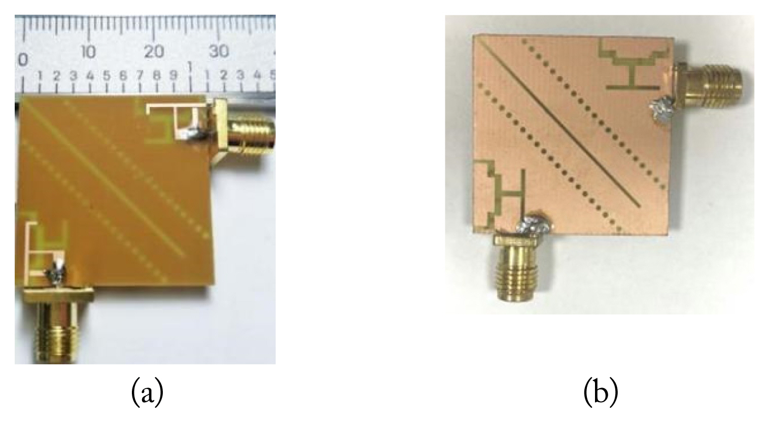
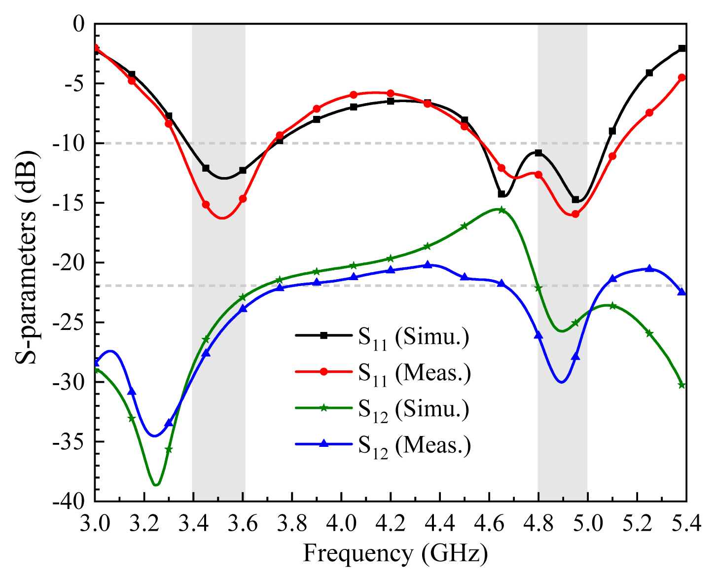
Following the design process, the antenna prototype was manufactured, the photograph of which is illustrated in Fig. 11. Fig. 12 shows the specific circumstances of the measured and simulated S-parameters of the proposed antenna. The measured −10 dB impedance bandwidths are 380 MHz (3.34–3.72 GHz) and 560 MHz (4.57–5.13 GHz), which can sufficiently cover the 3.5 GHz (3.4–3.6 GHz) and 4.9 GHz (4.8–5 GHz) frequency bands. Furthermore, the measured and simulated isolation is also more than 23 dB and 22 dB, respectively.
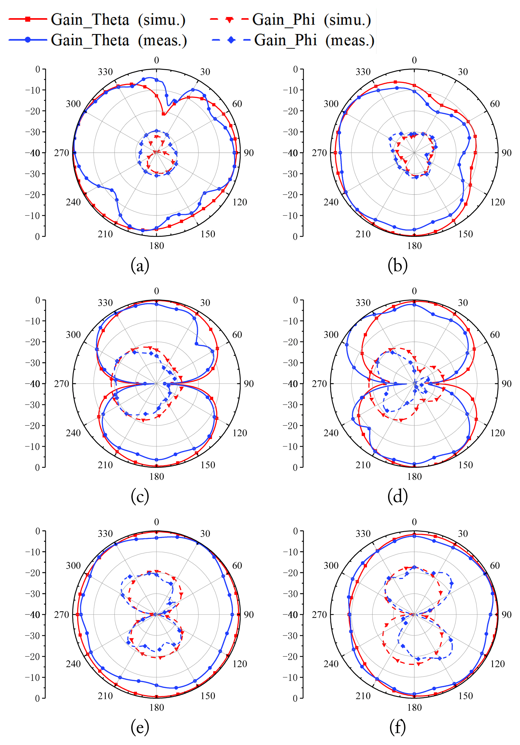
The measured and simulated radiation patterns at both 3.5 GHz and 4.9 GHz are demonstrated in Fig. 13, where Port 1 is excited while Port 2 is terminated by a 50-Ω matching load. The overall trend of the measured and simulated results is similar, while reasonable discrepancy is observed to be caused by the manufacturing process and proximity effect of the test setup (e.g., connectors, cables, and positioners).
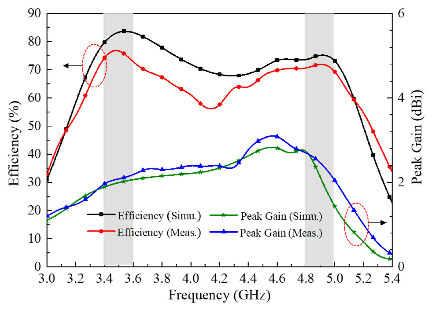
Fig. 14 illustrates the simulated and measured peak gains and total radiation efficiencies. The measured peak gains at 3.5 GHz and 4.9 GHz are 2 dBi and 2.46 dBi, respectively. Meanwhile, the total efficiencies at 3.5 GHz and 4.9 GHz are 76.65% and 71.93%, respectively. The results, therefore, exhibit good consistency between the simulated and measured peak gains and total efficiencies.
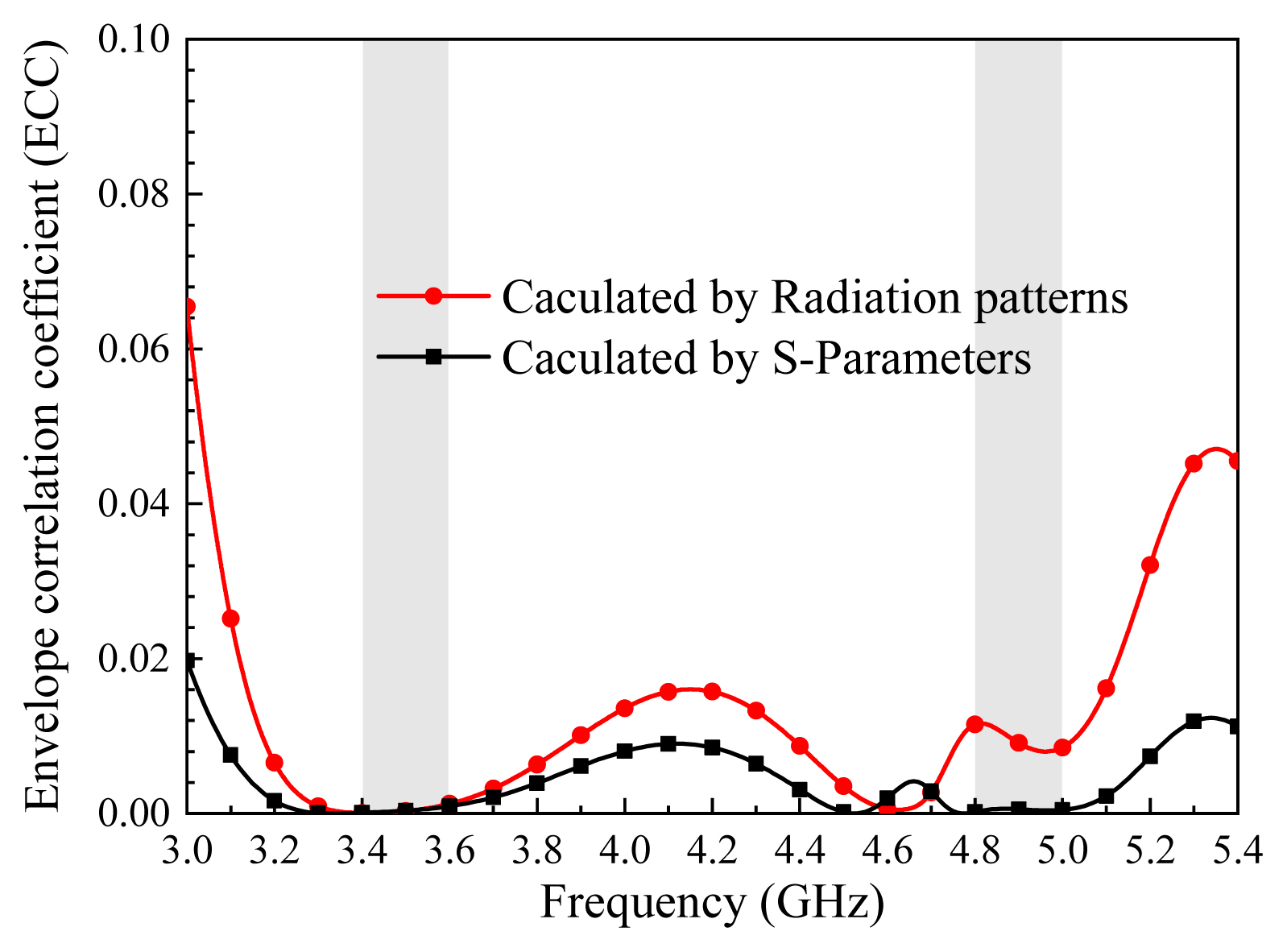
To further investigate the antenna performance, the ECC is calculated according to the far-field radiation patterns—expressed by Eq. (1).
where Fi(θ, ϕ) represents the radiation pattern when port i is excited, and Ω represents the solid angle.
The ECC calculation method using the S-parameters—a widely used process—is obtained from Eq. (2):
where S* represents the imaginary part of the S-parameters, while S′ represents their real part.
The calculated ECC is presented in Fig. 15. Since Eq. (2) considers only the isolation between the antenna input ports and does not take the coupling between the radiation fields into account, the obtained result is not as accurate as Eq. (1). The ECC calculated by the radiation patterns turns out to be less than 0.00125 and 0.01164 at the 3.5 GHz and 4.9 GHz bands, respectively. The calculated ECC is far smaller than the acceptable threshold of 0.3, meaning that the antenna system exhibits good diversity performance.
V. Effect on Users and SAR Investigation
In the case of a 5G terminal antenna, it is necessary to consider the effects of the human body on the antenna. Hence, this section simulates the working conditions of the antenna on the human wrist, as shown in Fig. 16.
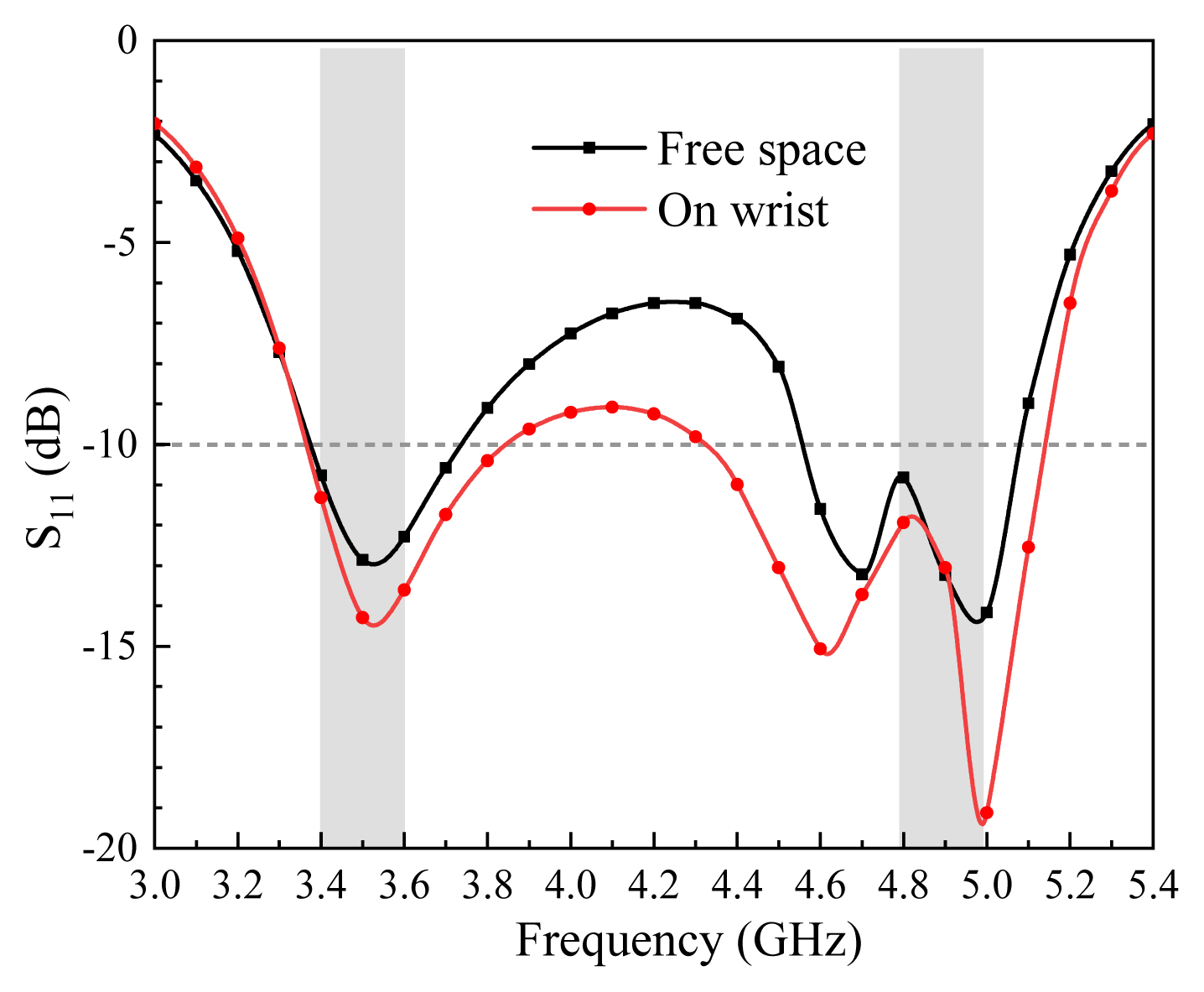
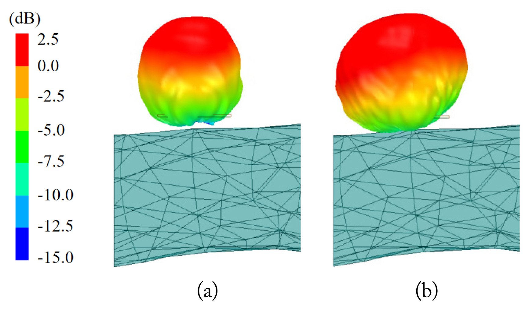
The simulated S11 values of the proposed antenna on the wrist are illustrated in Fig. 17. Although there are a few changes in the reflectance coefficients in the 3.5 GHz and 4.9 GHz bands, they still meet the requirements of the two bands. The overall trend in free space and the wrists is consistent due to the ground at the bottom. Fig. 18 shows the 3D radiation patterns of the proposed MIMO system on the wrist. The proposed MIMO antenna retains an adequate gain and a good radiation pattern.
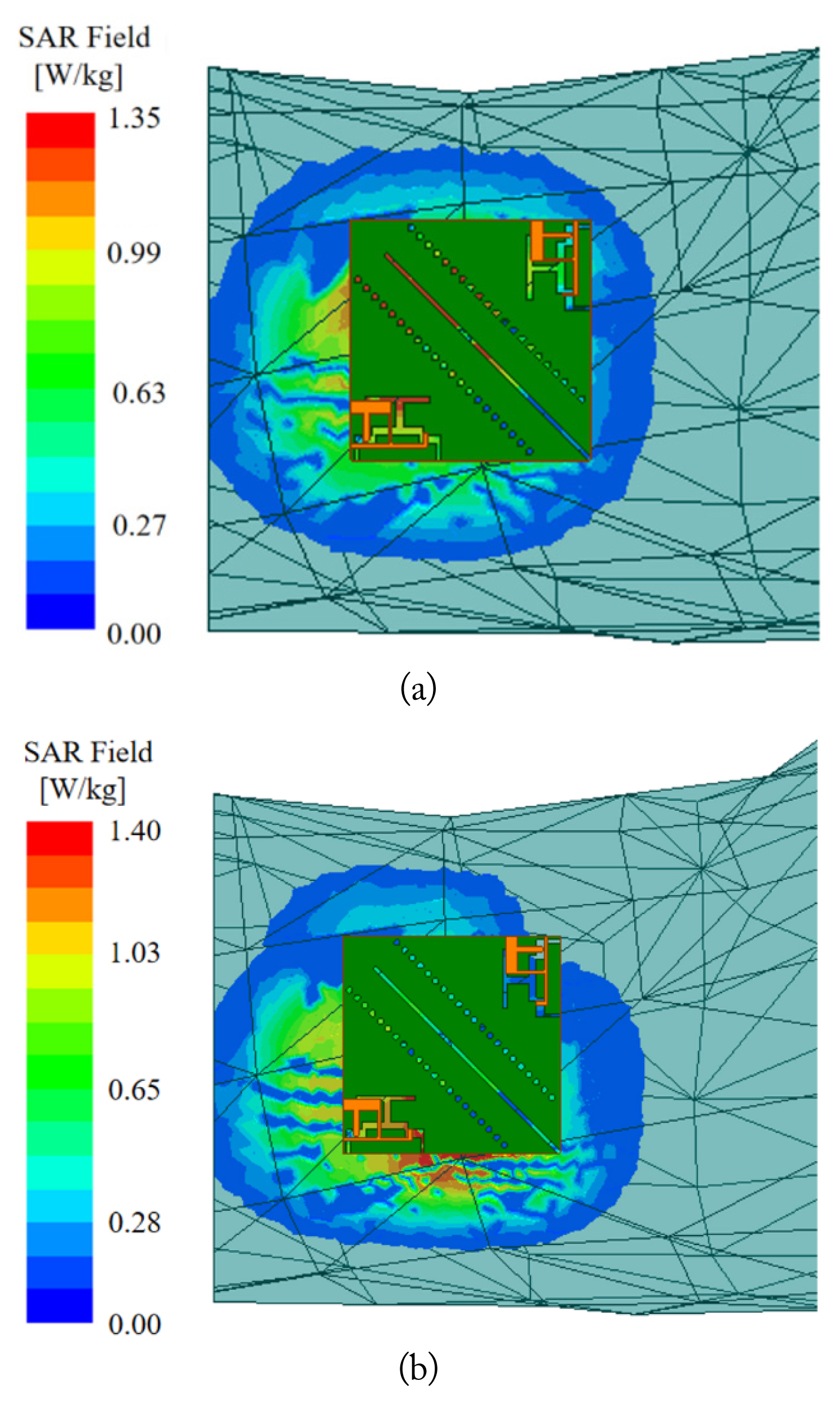
The SAR indicates the impact of device radiation on the human body, with a low SAR value demonstrating weak absorption of radiation by the human body. Fig. 19 shows a SAR simulation of the antenna on the wrist at 3.5 GHz and 4.9 GHz. The distance between the antenna and the wrist in this simulation is less than 4 mm. The results show that the 1 g average SAR values are less than 1.34 W/kg and 1.4 W/kg at 3.5 GHz and 4.9 GHz, respectively. Thus, the SAR level of the proposed antenna meets the standards of 1.6 W/kg per 1 g tissue in the United States.
Table 1 depicts a performance comparison of the proposed MIMO antenna and other reported antennas, highlighting the good isolation and compact structure of the former.
VI. Conclusion
A dual-band MIMO antenna operating in the 3.5 GHz band (3.4–3.6 GHz) and 4.9 GHz band (4.8–5 GHz) is presented in this study. The design evolution and dimension optimization of the single antenna element are analyzed to optimize antenna performance. The measured isolation of the antenna is observed to be more than 23 dB. The total efficiencies at 3.5 GHz and 4.9 GHz are about 76.65% and 71.93%, respectively. The results of the SAR analysis, simulated for the proposed terminal antenna, also meet the standard for terminal devices. Moreover, the measurement results are consistent with the simulation. Therefore, it can be concluded that the proposed MIMO antenna is a good candidate for use in 5G wireless communication systems.