Free-Space Unknown Thru Measurement Using Planar Offset Short for Material Characterization
Article information
Abstract
Material characterization requires the proper calibration of a material measurement system. This paper describes a free-space unknown thru measurement method using three independent planar metal offset shorts for calibrating a free-space material measurement system. This method is validated by comparing the measurement results with those of the TRL (thru-reflect-line) measurement method for two glass plates of 2.780 mm and 4.775 mm thickness in W-band (75–110 GHz). This can be an affordable and effective alternative to conventional free-space material measurement methods because the precision fabrication of a planar offset short is more feasible and inexpensive than building a precise positioning system in a free-space material measurement system. One can use this measurement method up to a high-frequency range that the fabrication accuracy of a planar offset short is acceptable.
I. Introduction
Recently, the application and use of electromagnetic (EM) materials, devices, and systems have become more prevalent in the natural and applied science fields, which need electrical parameters of EM materials, such as permittivity [1], permeability [2], and reflectivity [3], for analyzing and designing EM devices and systems.
The transmission/reflection (T/R) material measurement method [4–6], which is based on the properties of the transmission line—such as a closed guided-wave structure (e.g., coaxial line and waveguide) and an open guided-wave structure (e.g., free space)—is widely used for material parameter measurements. The closed guided-wave T/R material measurement method measures the scattering parameters of an MUT (material under test) located inside a closed guided-wave structure. This material measurement method is usually used in a low-frequency range, where precise machining for inserting the MUT into the guided-wave structure is available. On the other hand, the open guided-wave T/R material measurement method measures the scattering parameters of an MUT placed between two antennas in free space, as shown in Fig. 1. This material measurement method is suitable for non-destructive testing of an MUT without prior machining and physical contact at varying temperatures in a high-frequency range using the antennas with a manageable size. Meanwhile, the coaxial line T/R material measurement method [4, 7] can provide a broadband material parameter since the coaxial line supports the propagation of a TEM mode. In contrast, waveguide [5, 6] and free-space [8–11] T/R material measurement methods can only provide a frequency-banded material parameter due to limits on the operating frequency of the waveguide and antenna.
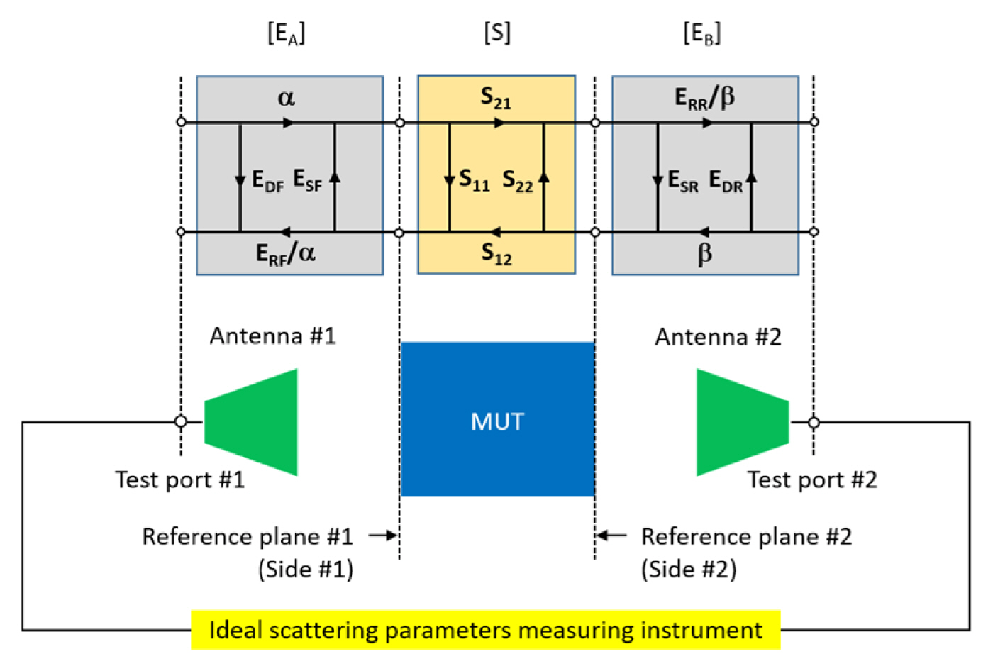
Two-port eight-term error model of a free-space T/R material measurement.
Usually, EM material measurements exhibit a discrepancy between the measured material parameter of an MUT and its real material parameter due to measurement errors in the measured parameter. From a metrological point of view, the measurement error consists of a systematic error, a random error, and a drift error. Systematic error, which is attributed to imperfections in a measurement system, is the most dominant among measurement error components. Systematic errors can be assumed to be time-invariant, modeled, and mathematically characterized during the calibration of a measurement system [12, 13].
In general, a free-space T/R material measurement consists of the following steps [8–11]:
Step 1. Calibrating a material measurement system including a scattering parameter measuring instrument, such as a vector network analyzer (VNA), to determine the reference planes (#1 and #2) of the measurement system for both sides (#1 and #2) of an MUT between two antennas, as shown in Fig. 1;
Step 2. Measuring the scattering parameters of the MUT using the calibrated material measurement system; and
Step 3. Extracting the material parameters of the MUT from the measured scattering parameters using EM theory.
Accurate and precise measurement of an MUT’s scattering parameters is essential to improving the measurement uncertainty of parameters extracted from a T/R material measurement. Notably, measurement uncertainty depends on the characteristics of the impedance standards and the method used to calibrate a material measurement system.
Free-space calibration methods, such as the TRL (thru-reflect-line), TRM (thru-reflect-match), and GRL (gated-reflect-line) methods, are widely used for T/R material measurement. The TRL method [8, 9] requires a precise positioning system to adjust the separation distance between an antenna and an MUT in free space. This method is susceptible to measurement errors due to the movement of the RF cable that is used to connect the antenna to the scattering parameters measuring instrument. Meanwhile, the TRM method [14], as a variant of the TRL method, may be used in a low-frequency range where a well-matched broadband EM absorber is available. The GRL method [15] requires a time-gating measurement and a planar metal plate that is as thick as an MUT during calibration, as well as a de-embedding process to compensate for the effect of the difference in thickness of the planar metal plate and the MUT during measurement. Effectively, the TRM and GRL methods can be applied to cases where both the MUT and antenna are fixed and avoid the movement of RF cable.
On the other hand, the unknown thru calibration method [16, 17], also called the SOLR (short-open-load-reciprocal thru) calibration method, is used for measuring the scattering parameters of non-insertable two-port DUTs (devices under test) whose connectors cannot mate together, such as a coaxial to waveguide adapter. The unknown thru calibration method is composed of (i) one-port calibration at each reference plane of a measurement system, where it needs at least three reflect standards (e.g., short, open, and load for a coaxial case; short, offset short, and load for a waveguide case), and (ii) an additional unknown thru measurement of a reciprocal two-port device.
Three independent reflect standards are essential to perform an unknown thru calibration. If a free-space material measurement system can change the separation distance between an antenna and a reflect standard using a precise positioning system [18], it would be easy to realize the reflect standards of the different properties by varying the separation distance. If not, it would be difficult to apply the unknown thru calibration method to a free-space material measurement because discovering independent reflect standards is rather difficult.
Recently, a free-space unknown thru calibration method [19] that uses planar offset shorts as the free-space reflect standard [20, 21] was applied to demonstrate its feasibility in calibrating a free-space material measurement system without a precise positioning system. This paper extends this test of feasibility by adding a detailed description of the calibration procedure and measurement system and analyzing the measurement results. To the best of our knowledge, this study is the first to deal with the realization of the unknown thru calibration method for free-space material measurement.
Section II of this paper briefly describes the use of a planar offset short as a free-space calculable reflect standard and its significance. Section III describes the free-space unknown thru measurement method using planar offset short and its advantages. In Section IV, the free-space unknown thru method is validated by comparing the measurement results with those of the TRL method for two MUTs (glass plates of 2.780 mm and 4.775 mm thickness) using a quasi-optic-based free-space material measurement system in W-band (75–110 GHz). Finally, Section V summarizes this paper.
II. Free-Space Calculable Reflect Standard
Assume that a Gaussian beam, as a localized plane wave, is incident upon the central area of a square metal plate whose size (D) is kept at least three times larger than the waist (d) of the Gaussian beam in order to avoid the edge diffraction effect by the metal plate in quasi-optic-based free-space measurements [22], as shown in Fig. 2 (left). If the central area recedes by an offset (l) (i.e., if the offset short plane is located at a distance from the reference plane, as shown in Fig. 2 (right)), the reflection coefficient of the planar offset short at the reference plane may be expressed by [23]:
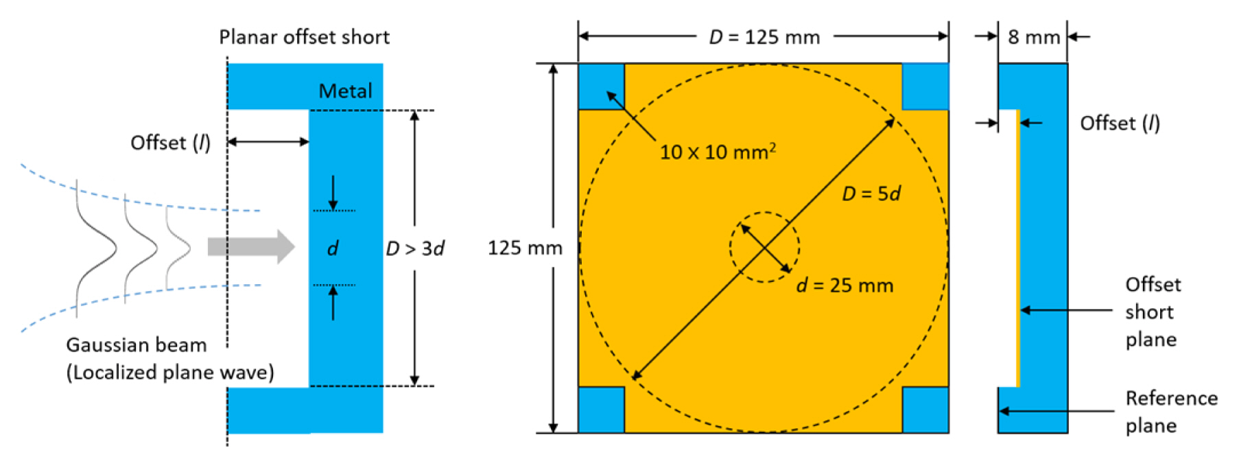
where j and k denote the imaginary unit and wavenumber, respectively. Eq. (1) suggests that the planar metal offset short is suitable for utilizing as a free-space calculable reflect standard with the following reflection properties: (i) the magnitude of the reflection coefficient is unity, regardless of the offset and signal frequency, and (ii) its phase is linearly proportional to the offset and frequency.
This paper uses a planar offset short of 125 mm × 125 mm mm2 and 8 mm thickness, as shown in Fig. 2 (right), where the size (D = 125 mm) of its central area is five times larger than the waist (d = 25 mm) of the Gaussian beam incident upon the central area in a W-band free-space material measurement system [20, 21].
III. Free-Space Unknown Thru Measurement
A free-space unknown thru measurement method uses the same calibration theory as a closed guided-wave unknown thru measurement method [16, 17]. However, there are some differences between the two measurement methods in terms of their actual measurements.
1. Two-Port Eight-Term Error Modeling and Its Cascade Matrix Representation
A free-space T/R material measurement system may be represented as a two-port eight-term error model, as shown in Fig. 1. It is composed of the following parts:
- An MUT is placed at the middle of two antennas (#1 and #2) in free space, where both sides (#1 and #2) of the MUT are assigned to the reference planes (#1 and #2) of the material measurement system;
- An ideal scattering parameter measuring instrument for measuring the scattering parameters of the MUT, where the test ports (#1 and #2) of the measuring instrument are connected to the two antennas (#1 and #2); and
- Two error adapters (EA and EB) describing the non-ideal parts between the reference plane (#1 and #2) and the test port (#1 and #2), modeled as four systematic errors at each side (#1 and #2) of the MUT, where (EDF,ESF,ERF) and (EDR,ESR,ERR) denote the one-port systematic error corresponding to directivity, port match, and reflection tracking, respectively, on each error adapter, while α and β are the systematic errors related to transmission tracking on each error adapter. Effectively, eight systematic errors can be determined during the calibration of the material measurement system.
The eight-term error model may be expressed in the cascade matrix by:
where [Tm] and [T] denote the cascade matrices of the measured scattering matrix [Sm] and the real scattering matrix [S] of an MUT, respectively, while [A] and [B] represent the cascade matrices of the scattering matrix of error adapters EA and EB, respectively. [Tm], [A], and [B] in Eq. (2) can, therefore, be expressed as:
where Sij,m denotes the element of [Sm], ΔS,m= −det [Sm], ΔA= −det[EA], and ΔB= −det[EB]. Substituting Eqs. (4) and (5) in Eq. (2) leads to [Tm] being expressed in only seven unknowns—(EDF,ESF,ERF), (EDR,ESR,ERR), and β/α—which can be denoted as:
From Eq. (6), [T] may be expressed as:
The two one-port systematic errors—(EDF, ESF, ERF ) and (EDR,ESR,ERR)—can be determined by performing the one-port calibration at each reference plane (#1 and #2) of the material measurement system. From Eq. (6), the remaining unknown α/β may be expressed as:
by using the property that the determinant of the cascade matrix of a reciprocal two-port device is equal to unity. The sign ambiguity in Eq. (8) can be solved by comparing the calculated and measured transmission coefficients of the reciprocal two-port device.
According to the unknown thru calibration theory [16, 17], an unknown thru standard (i.e., a reciprocal two-port device) used for determining α/β does not need to be known or perfect. However, the unknown thru standard must be reciprocal, must be aware of the phase within a quarter wavelength, and is additionally recommended to have a transmission loss less than 40 dB for accurate determination of α/β during calibration. If a DUT meets these requirements, it can be considered the unknown thru standard.
2. Procedure of Free-Space Unknown Thru Calibration and Measurement
The steps to conduct a free-space unknown thru calibration and measurement are as follows:
Step 1. Determining the one-port systematic error (EDF,ESF,ERF) at reference plane #1 by performing the one-port calibration with three free-space reflect standards;
Step 2. Repeating Step 1 to determine the other one-port systematic error (EDR, ESR, ERR ) at reference plane #2, which is situated away from reference plane #1 due to the thickness of an MUT; and
Step 3. Determining the remaining unknown α/β by performing an unknown thru measurement. If the MUT, which is placed between the two reference planes (#1 and #2), meets the requirements of the unknown thru standard, it is used as the unknown thru standard in the calibration. Otherwise, an air gap with the same thickness as the MUT is used as the unknown thru standard.
Step 4. If an MUT meets the requirements of the unknown thru standard, its scattering parameters are measured using the calibrated free-space material measurement system without changing the calibration setup. Otherwise, the scattering parameters of the MUT are measured by replacing the air gap with the MUT.
IV. Free-Space Unknown Thru Measurement Results
The scattering parameters of two reciprocal MUTs (glass plates of 2.780 mm and 4.775 mm thickness) are measured by using a quasi-optic-based free-space material measurement system [18], as shown in Fig. 3, which is calibrated by the free-space unknown thru and TRL methods for 500 Hz IF bandwidth and 801 frequency sweep points in W-band.
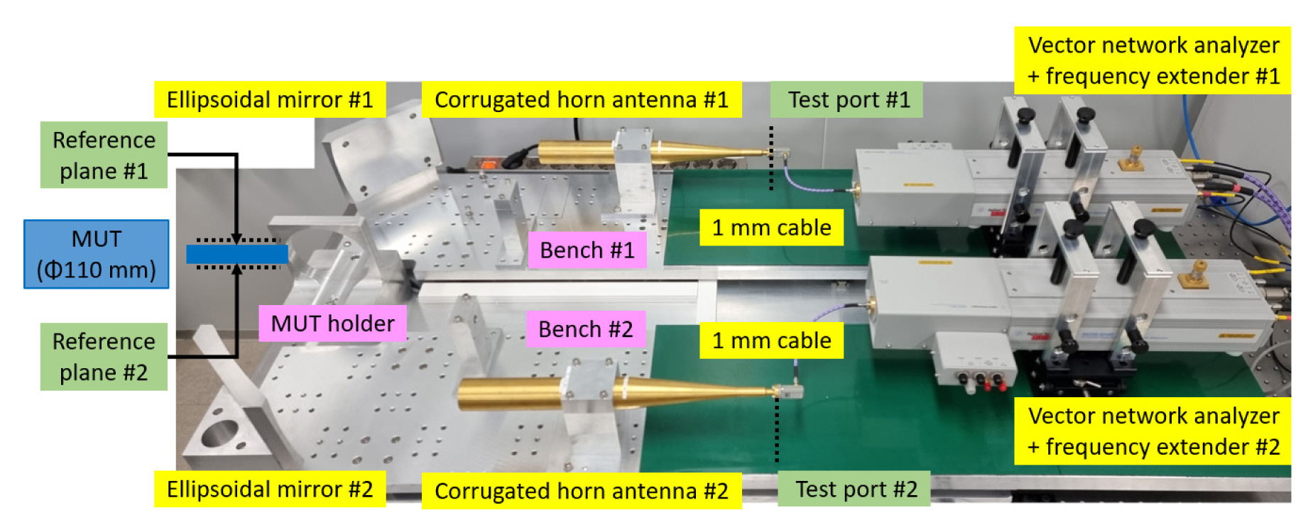
Quasi-optic-based free-space material measurement system in W-band.
The quasi-optic-based free-space material measurement system is composed of the following parts:
- A millimeter-wave scattering parameters measuring instrument consisting of a VNA and two frequency extenders; and
- A quasi-optic-based free-space instrument composed of two linearly movable benches with an MUT holder between them, where each bench has a Gaussian beam forming corrugated horn antenna and an ellipsoidal refocusing mirror and is capable of independently changing the separation distance between the bench and the MUT holder for supporting TRL calibration.
The free-space unknown thru and TRL calibrations are performed as follows:
- Free-space unknown thru calibration is carried out by measuring: (i) the one-port calibration at the reference planes corresponding to both sides of the MUT using three planar offset “Shorts” (l = 0 mm, 0.550 mm (λ/6), 1.100 mm (2λ/6)), generating a phase difference of 120° between the reflection coefficients of the planar shorts at the center frequency of the W-band [21], and (ii) the “unknown Thru” after inserting an MUT between the two reference planes. Since the two reference planes (#1 and #2) of the measurement system are fixed during the calibration, movement of the RF cable can be avoided. Meanwhile, the reflection coefficients of the three reflect standards used in the one-port calibration should not be equal to each other, and should be distributed as far as possible from each other on the complex reflection plane in the operating frequency range. The theoretical magnitude of the reflection coefficient of the three planar offset shorts (0 mm, 0.550 mm, and 1.100 mm) is unity, regardless of the offset and signal frequency. The theoretical phase of the planar flush (0 mm offset) is −180°, irrespective of the signal frequency, while that of the two planar offset shorts is changed from 80.96° to 34.75° for the 0.550 mm offset, and from −18.07° to −110.51° for the 1.100 mm offset in the W-band [21]. Therefore, the three planar offset shorts can be used as independent reflect standards in the one-port calibration; and
- TRL calibration is carried out by measuring: (i) the zero-length “Thru” by directly connecting the reference planes (#1 and #2), (ii) the “Reflect” using a metal plate (4.671 mm thickness) inserted between the two reference planes, which are consequently separated by the plate thickness, and (iii) the “Line” of a quarter-wavelength delay (0.82 mm length) in the air, which separates the reference planes. Since reference plane #1 of the measurement system is fixed during the calibration, movement of the RF cable is inevitable.
The scattering parameters of a glass plate of 2.780 mm thickness are measured five times to compare the repeatability of the measured results obtained from the free-space unknown thru (solid symbol) and TRL (open symbol) calibration methods, as shown in Fig. 4. The average and standard deviation of the measured magnitude and phase data exhibit some peaks in the measured data due to multiple reflections between the MUT and antennas as well as within the MUT itself, which is inherent in a free-space material measurement.
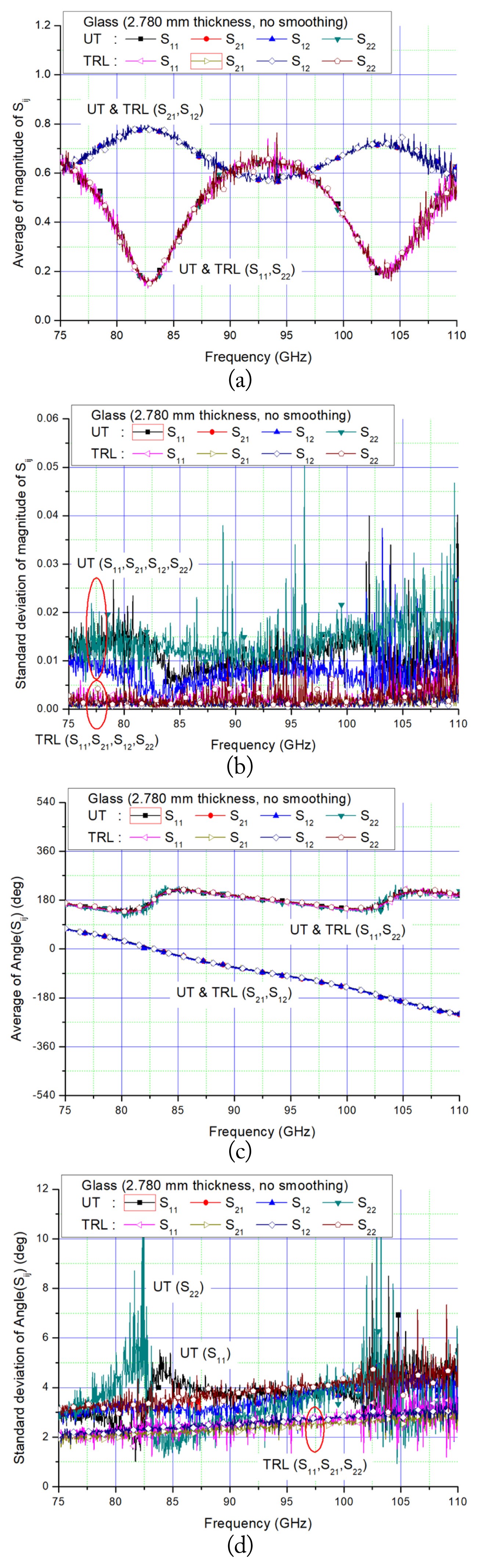
Average and standard deviation of the magnitude and phase of the scattering parameters, measured five times, of a glass of 2.780 mm thickness obtained from free-space unknown thru (UT, solid symbol) and TRL (open symbol) calibration methods without any smoothing process: (a) average of the magnitude, (b) standard deviation of the magnitude, (c) average of the phase, and (d) standard deviation of the phase.
Usually, these multiple reflections can be removed by implementing smoothing (i.e., moving average) and time-gating of the measured data as post-signal processing. The application of 10-point smoothing to the measured data, as depicted in Fig. 4, reveals that (i) the effects of the multiple reflections on the magnitude and phase data are drastically reduced, (ii) the averages of the magnitude and phase obtained from the two calibration methods agree with each other, as shown in Fig. 5(a) and 5(c), which validates the free-space unknown thru calibration method, and (iii) the standard deviations of the magnitude and phase obtained from the TRL calibration method are more favorable than those obtained from the unknown thru method, as shown in Fig. 5(b) and 5(d).
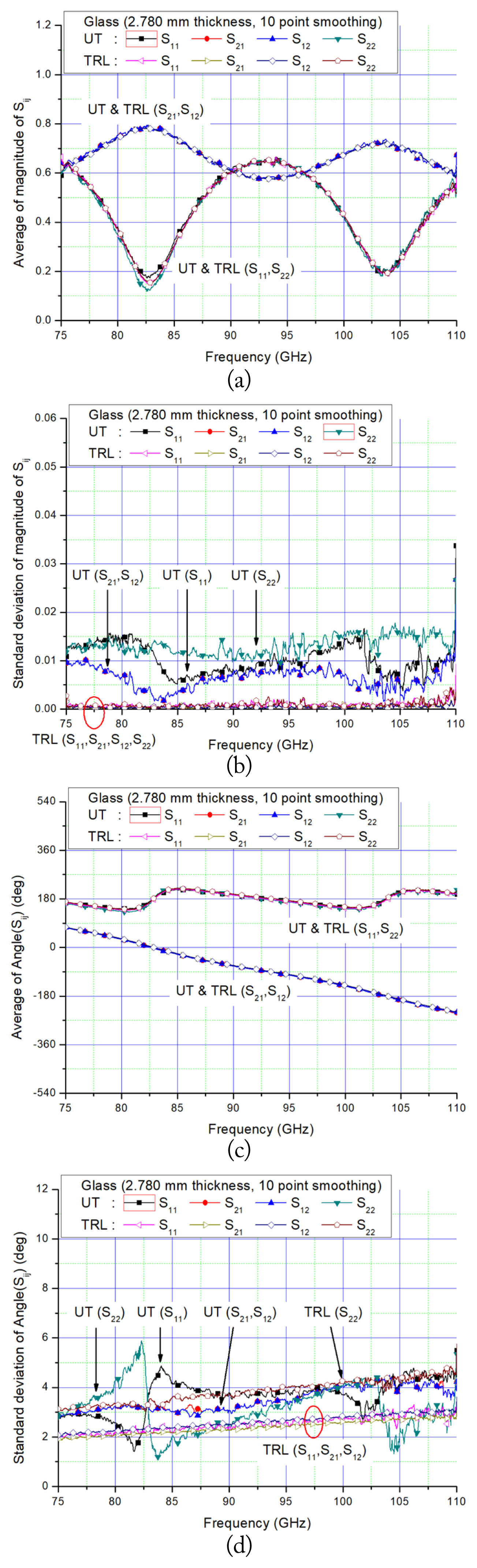
Average and standard deviation of the magnitude and phase of the scattering parameters, measured five times, of a glass of 2.780 mm thickness obtained from free-space unknown thru (UT, solid symbol) and TRL (open symbol) calibration methods with a 10-point smoothing process: (a) average of the magnitude, (b) standard deviation of the magnitude, (c) average of the phase, and (d) standard deviation of the phase.
Increasing the thickness of the glass plate from 2.780 mm to 4.775 mm results in a reduction of the multiple reflections on the measured data, a shorter period of the magnitude of reflection and transmission coefficients, and a steeper phase slope of the transmission coefficient, as shown in Fig. 6.
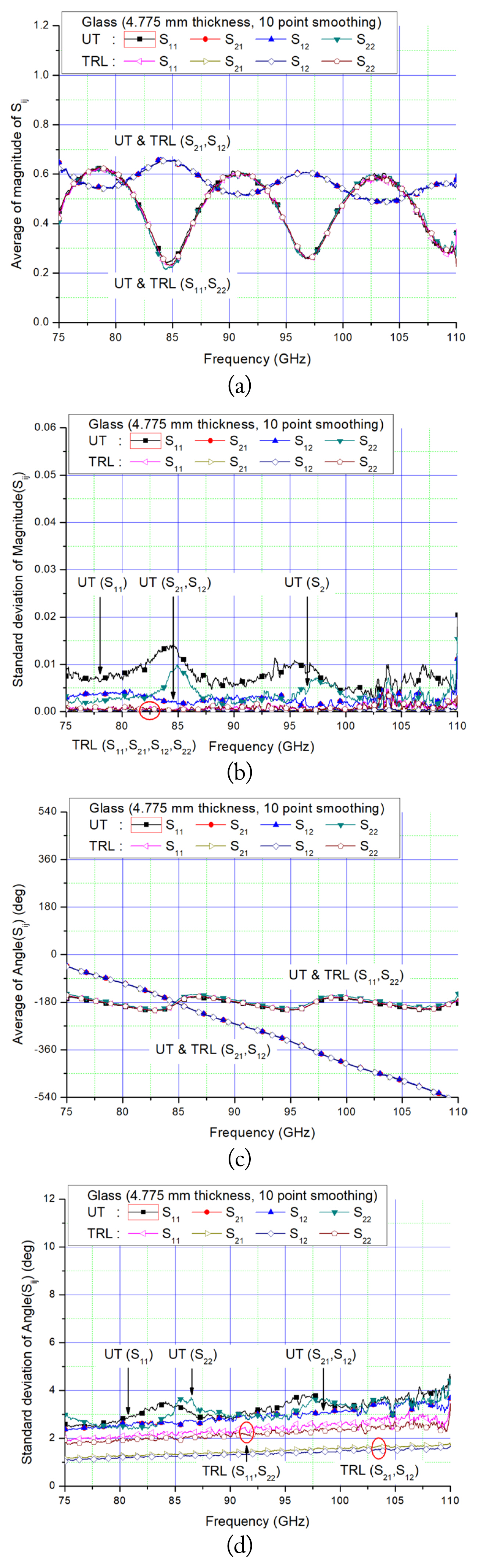
Average and standard deviation of the magnitude and phase of the scattering parameters, measured five times, of a glass of 4.775 mm thickness obtained from free-space unknown thru (UT, solid symbol) and TRL (open symbol) calibration methods with a 10-point smoothing process: (a) average of the magnitude, (b) standard deviation of the magnitude, (c) average of the phase, and (d) standard deviation of the phase.
The measurement results suggest that the TRL calibration method has better reproducibility (i.e., standard deviation) than the unknown thru calibration method, which involves complicated measurement procedures compared to the TRL calibration method, as shown in Figs. 5 and 6. However, discrepancies between the measured results can be improved by the accurate alignment and placement of the reflect standard and the MUT in the material measurement.
Compared to conventional free-space measurement methods, such as the TRL, TRM, and GRL methods, the free-space unknown thru measurement method using plane offset shorts has the advantages of not using the followings:
- A precise positioning system and movement of RF cables in the TRL method.
- A well-matched broadband EM absorber in the TRM method.
- A time-gating measurement and a planar metal plate that is as thick as a MUT during calibration and a de-embedding process to compensate for the effect of the difference in thickness of the planar metal plate and the MUT in the GRL measurement method.
V. Conclusion
Material characterization requires the proper calibration of a material measurement system. This study describes a free-space unknown thru measurement method using three independent planar metal offset shorts for calibrating a free-space material measurement system.
The scattering parameters of two glass plates, with 2.780 mm and 4.775 mm thickness, obtained from conducting the free-space unknown thru and TRL measurement methods, agree with each other in W-band. This implies that the free-space unknown thru measurement method using planar offset shorts can be considered an affordable and effective alternative to conventional free-space material measurement methods.
This study further highlights that the precision fabrication of a planar metal offset short is more feasible and inexpensive than building a precision positioning system in a free-space material measurement system. This measurement method can be used even for a high-frequency range that the fabrication accuracy of a planar metal offset short finds acceptable. This method can be helpful for microwave, millimeter-wave, and sub-millimeter-wave material measurements.
Acknowledgments
This study is supported by the Technology Innovation Program (No. 20016225, Development and Dissemination on National Standard Reference Data) funded by the Ministry of Trade, Industry & Energy, Republic of Korea, and the Korea Research Institute of Standards and Science (No. KRISS-2021-21011008) under the project “Development of safety measurement technology for major infrastructures.”
References
Biography

Jin-Seob Kang received his B.S. degree in Electronic Engineering from Hanyang Unversity, Seoul, Korea, in 1987, and his M.S. and Ph.D. degrees in Electrical and Electronic Engineering from Korea Advanced Institute of Science and Technology (KAIST), Daejeon, Korea, in 1989 and 1994, respectively. He was a postdoctoral research associate with the Department of Electrical and Computer Engineering, University of Illinois at Urbana-Champaign in 1995, and an assistant professor with the School of Electrical and Electronic Engineering, Chungbuk National University, Korea, from 1996 to 1997. He joined the Korea Research Institute of Standards and Science (KRISS), Daejeon, in 1998 and currently serves as a principal research scientist. He has been working on electromagnetic (EM) measurement standards, material measurements, material parameter reference standards, (sub-)mm-wave EM measurements, and non-destructive testing.