Wireless Power Transfer-Based Microrobot with Magnetic Force Propulsion Considering Power Transfer Efficiency
Article information
Abstract
A microrobot that could continuously receive both electrical energy and propulsion force from a wireless power transfer system would offer tremendous benefits. However, wireless powering systems produce a time-varying magnetic field that can be harmful if the generated magnetic field needed for microrobot movement is large. To limit exposure, power transfer efficiency must be enhanced. This paper derived and analyzed the magnetic force applied to a microrobot from a wireless power transfer system. Unlike previously introduced Lorentz force-based microrobot propulsion, the proposed method is independent of a wireless power transfer system’s frequency. Therefore, this frequency can be determined considering maximum power transfer efficiency. The theoretical analysis and simulation by numerical analysis were compared, and results were verified though actual fabrication and measurement. Analyses of the transmitting and receiving coils were conducted. The optimum force, with less than 9% discrepancy, was determined while achieving a 3.6% improvement in power transfer efficiency.
I. Introduction
Microrobots have recently been investigated for use as implantable medical devices because their various features offer tremendous benefits [1, 2]. To enable their practical implementation as implantable medical devices, the size of the microrobot should be small enough to insert it into a blood vessel. The microrobot should also be capable of moving from one position to another intended position. For this reason, microrobot propulsion systems are one of the most significant areas of research in the field. Microrobot sizes can range from nanometers to millimeters, and various propulsion methods have been considered based on their size and likely operating environments [3–8]. To power the active circuits of the microrobot, a battery system has been developed [9]. However, the battery is not yet small enough for an implantable microrobot. Since the capacity of a battery is determined by its volume, reducing the battery’s size also limits its operating time.
To address this power issue, wireless power transfer (WPT) systems have been widely studied for use in microrobots [10–13]. The WPT systems transfer electrical energy wirelessly and continuously, which means that a WPT-supplied microrobot has unlimited operating time as long as the power continues to be supplied from outside. Some researchers have adopted a motor-based propulsion system to provide movement [12, 13], but the miniaturization of these kinds of motor systems is not easy. To address this issue, a microrobot with combined propulsion and a WPT system was recently introduced [14–20]. This microrobot propulsion method is based on Lorentz force. The authors used a time-varying magnetic field formed by the transmitting of a WPT system, and induced current as the source of Lorentz force. To generate the Lorentz force, it was necessary to avoid the inductor-capacitor (LC) resonance frequency, which can decrease power transfer efficiency [14–17]. In addition, as the size of the microrobot is reduced, the generated Lorentz force decreases, as the length that is affected by the time-varying magnetic field is reduced.
To overcome this phenomenon, a novel microrobot propulsion method that uses the WPT system, as inspired by the magnetophoretic force, was developed [18–24]. In this approach, a bar-type magnetic material is used to produce a magnetic force, using the time-varying incident magnetic field inherently generated by the WPT system [20]. This allows the magnetic force to be used as the microbot’s source of propulsion.
As is well known, the magnetic force on a magnetic material is proportional to the magnitude of an incident magnetic field. However, overly time-varying magnetic fields can be potentially harmful to the human body. Therefore, estimating the magnetic force of the microrobot is important. Fortunately, increasing the efficiency of the microrobot WPT will result in a lower incident magnetic field at the same time.
In this study, we derived and analyzed the instantaneous magnetic force generated on a magnetic material embedded in the microrobot at the center of the transmitting coil. Since the relative permeability of a magnetic material is affected by magnetic force, the effect of relative permeability was analyzed theoretically and verified by simulation. The results showed that the discrepancy between the derived magnetic force and the simulated force was less than 9%. Additionally, various transmitting coils and receiving coils were fabricated and analyzed to obtain high power transfer efficiency. The resulting power transfer efficiency was derived using Q-factors and the coupling coefficient (k). As a result, it was possible to achieve a 3.5% power transfer efficiency in a 2 mm × 2 mm × 4 mm microrobot at 220 kHz.
II. Derivation of Magnetic Force Applied to Magnetic Material
1. Magnetic Force Applied to a Magnetic Material Exposed to a Static Magnetic Field
The magnetic force on a magnetic particle under a static magnetic field can be obtained as (1) [18, 21, 22]:
where r, rp, μp, μm, and H represent the distance from the center of the coil to the magnetic material, the radius of the particle, the relative permeability of the particle, the relative permeability of the media, and the magnetic field vector, respectively.
Since this research deals with implantable microrobots, it is reasonable to set μm as 1 since the media is assumed to be a blood vessel, while μp is in the range of 100–3,200, depending on the synthesis method and procedures used for the magnetic materials [25, 26]. As can be expected, according to Eq. (1), when the μp is higher than the relative permeability of the media, the term (μp − μm)/(μp + 2μm) is negligible since it approaches the value of 1.
To validate this phenomenon, a simple simulation setup was established, as shown in Fig. 1. In this research, we used the finite element method solver ANSYS Electronics. A constant current of 0.25 mA was excited in the coil to generate a magnetic field. The coil size was set at 2 μm by referring to a previous study [18]. A spherically shaped magnetic particle with a radius of 1/30 μm was located along the center of the coil and y-axis. The simulation was performed by changing the location of the magnetic particle from −6 μm to 10 μm in steps of 0.5 μm with various values of μp. Depending on the magnetic particle’s position or the distance between the magnetic particle and the coil, the applied magnetic force was changed.
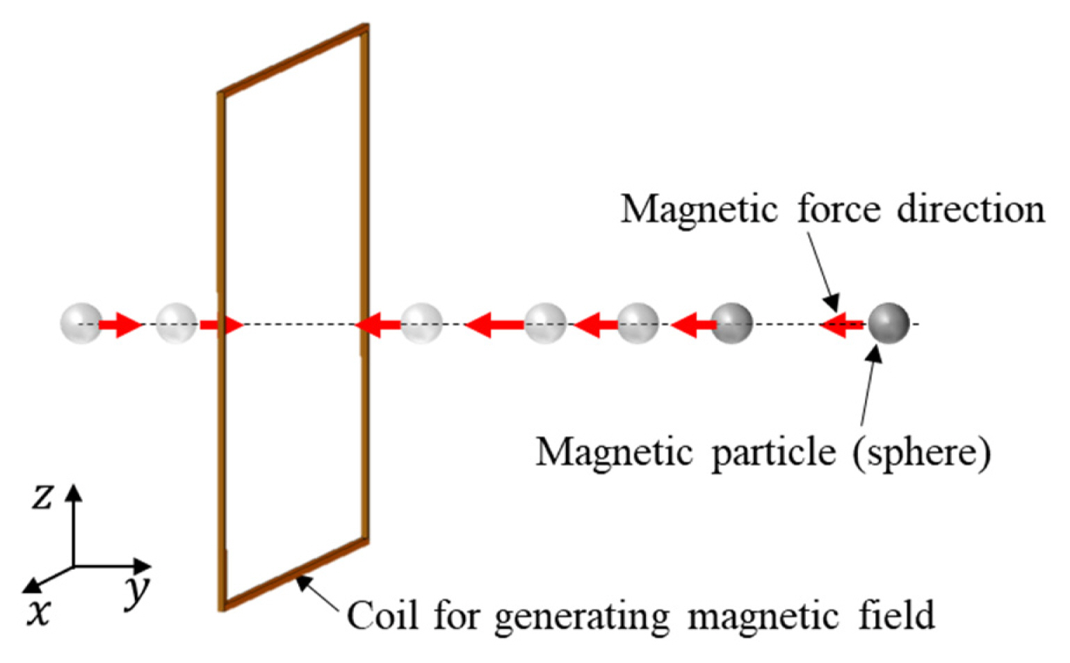
Simulation setup used to extract the magnetic force applied to the magnetic material, which was generated by an incident magnetic field.
To determine the permeability of the magnetic material, we changed the ferrite’s permeability to 10, 50, 150, and 3,000. As shown in Fig. 2, as the μp becomes larger, the magnetic force on the magnetic particle converges to a solid line, since the (μp − μm)/(μp + 2μm) term approaches 1.

Magnetic force with different relative permeabilities.
2. Magnetic Force Applied to a Magnetic Material Exposed to a Time-Varying Magnetic Field
Since the WPT system generates a time-varying magnetic field, the static magnetic field term (H) in Eq. (1) can be substituted with (H(r)sin(ωt)2), where ω is the angular frequency. Hence, the magnetic force on a spherically shaped magnetic material can be modified using Eq. (2) [23].
Accordingly, the time-average magnetic force on a magnetic material can be obtained using Eq. (3).
Based on Eq. (3), it is clear that the powering frequency is not affected by the magnetic force, which makes it easier to design the WPT system.
To validate this idea, simulations of instantaneous force and time-average force were conducted. To generate the time-varying magnetic force, a 0.25 mA, 220 kHz sinusoidal current was applied to the coil while the other parameters were maintained.
The calculated and simulated results are compared in Fig. 3, which shows there was less than a 2% discrepancy in terms of the magnitude of magnetic force.
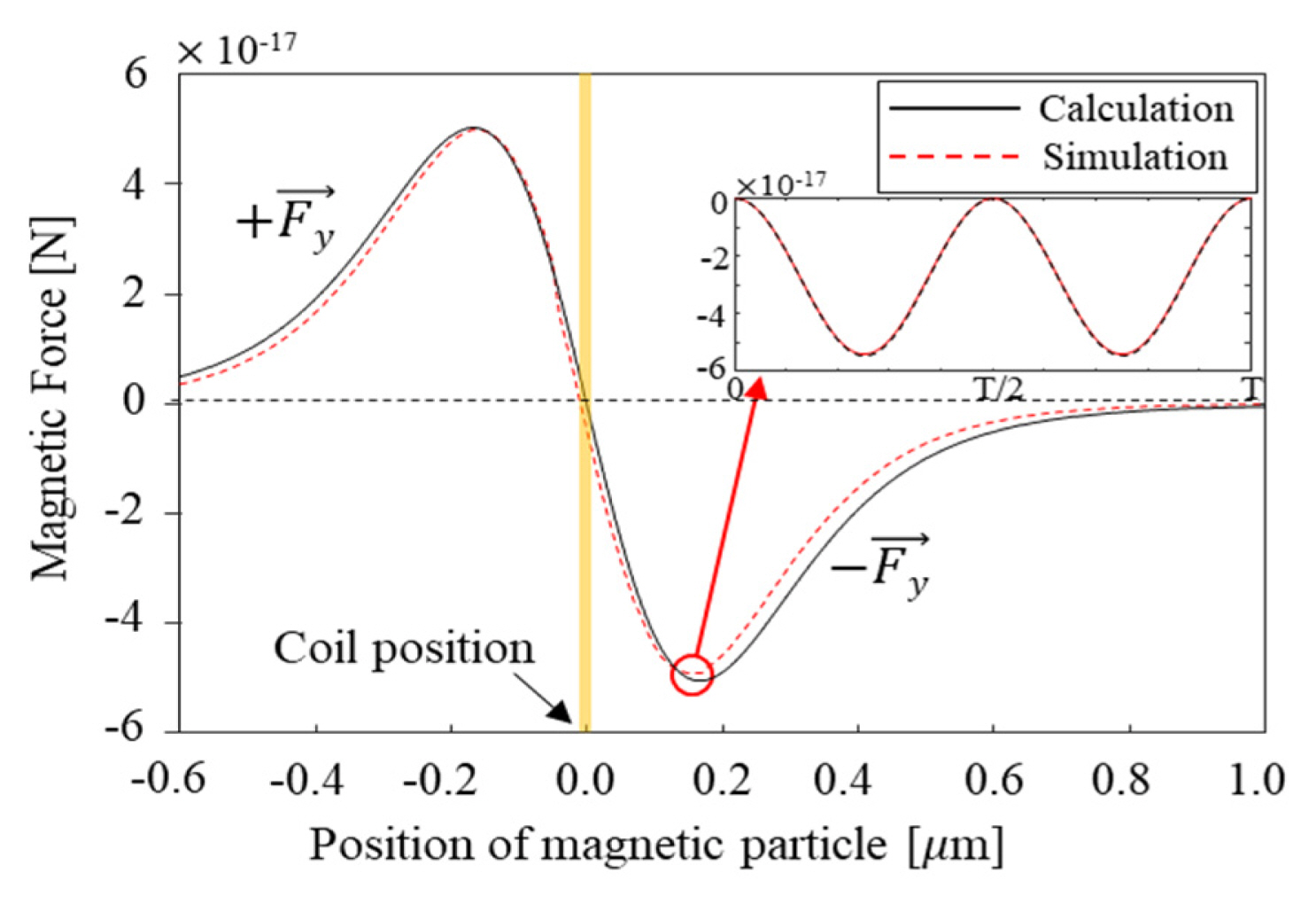
Time-average magnetic force under a time-varying magnetic field.
3. Magnetic Force Applied to a Magnetic Bar Exposed to a Time-Varying Magnetic Field
According to Eq. (3), a higher magnetic field gradient generates a higher magnetic force. In other words, bar-shaped magnetic material has advantages for propulsion since it will be exposed to a higher magnetic field gradient [21]. For this reason, a bar-shaped magnetic material was used in this research. By applying volume integration to Eq. (3), the force on the magnetic bar can be derived as Eq. (4).
To validate this equation, a simulation was conducted, as illustrated in Fig 4(a). A 2 mm × 2 mm × 4 mm magnetic bar was exposed to the time-varying magnetic field and moved from the center of the coil to 50 mm away from the center along the normal direction following the y-axis.
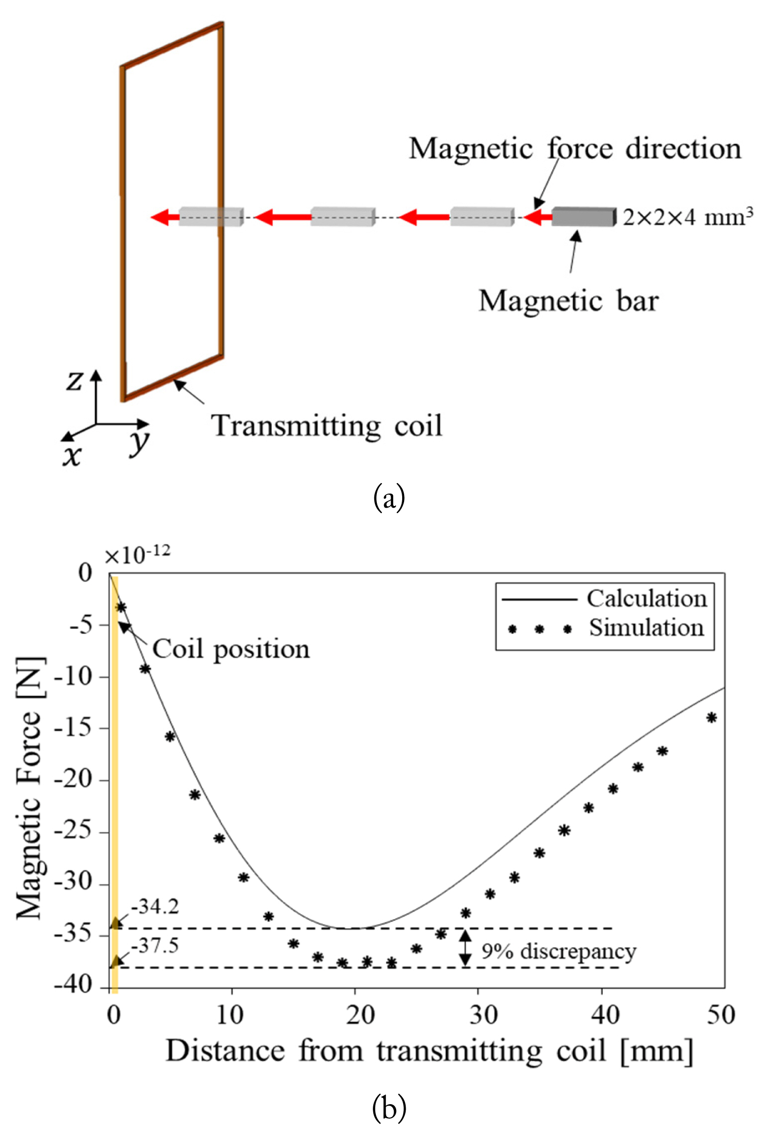
Calculated and simulated time-average magnetic force on a magnetic bar. (a) Simulation setup and (b) obtained force at specific distances from the coil (0 mm to 50 mm).
The tendencies of the calculated and simulated values corresponded highly to each other with less than 9% discrepancy. As a result, we could determine the magnitude of the incident magnetic field and therefore the applied current on a coil.
III. Power Transfer Efficiency Analysis based on Q-Factors and Coupling Coefficient
The magnitude of the incident magnetic field at a certain distance is determined by ampere turns. The size and number of turns in the coil affect the quality factor (Q-factor) and the coupling coefficient (k) between the transmitting coil and the receiving coil, which is directly related to the power transfer efficiency. Accordingly, a Q-factor-based analysis is necessary to determine the proper transmitting coil. According to Eq. (3), the square of magnetic field intensity is proportional to the generated magnetic force. Considering that the magnitude of the magnetic field is proportional to the exciting current on the transmitting coil, the magnitude of the incident magnetic field can be controlled by adjusting the current. Moreover, to generate a sufficient magnetic field, the input impedance should be low so that the current flows freely. For this reason, a series-series (SS) WPT topology system was employed in this research.
Fig. 5 illustrates the general equivalent circuit of the SS topology. In this condition, the resonance frequency and Q-factors of the transmitting and receiving coils are as follows:
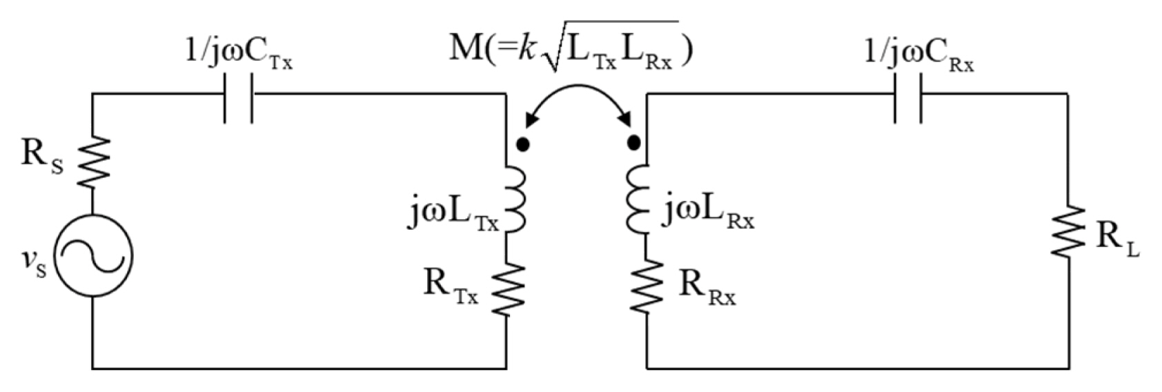
Equivalent circuit of the series-series (S-S) WPT system. The maximum power transfer can be obtained at the LC resonance frequency (ω0).
where, ω0, LTx, LRx, CTx, CRx, QTx, QRx, RTx, and RRx, are the resonance frequency, self-inductance of the transmitting coil, the self-inductance of the receiving coil, the capacitance of the transmitting part, the capacitance of the receiving part, the resistance of the transmitting coil, and the resistance of the receiving coil, respectively. Assuming that the RS, the resistance of the transmitting part, is small enough to be negligible, except for the transmitting coil resistance, the power transfer efficiency (η) of this system can be obtained as Eq. (5):
Therefore, when the Q-factors of the transmitting and receiving coils and the coupling coefficient between the two coils are given, the power transfer efficiency can be easily obtained.
IV. Determining Powering Frequency
To establish the experimental setup, two transmitting coils and three receiving coils were fabricated. Since it is difficult to estimate the resistance of the Litz wire, we measured the Q-factors and coupling coefficient using an Agilent E5071C vector network analyzer (VNA). The measurement was conducted while maintaining a 50-mm distance between the transmitting and receiving coils.
1. Q-Factor and Mutual Inductance Derivation from S-Parameters
The transmitting and receiving coils were connected to ports 1 and 2 of the VNA, respectively, to obtain the S-parameter. The sweeping frequency was set to 10 kHz–2 MHz. From the S-parameter, we derived the Z-parameter referring to Table D.1 [27]. After that, we took the real term of the Z-parameters of the transmitting (Z11) and receiving (Z22) coils to obtain the resistance RTX and RRX. For the inductance, which is mandatory below the self-resonance frequency (SRF), we took the imaginary parts of Z11 and Z22. After that, the self-inductance of each coil was calculated by taking the imaginary parts of Z11 and Z22, divided by the angular frequency. Similarly, to obtain the mutual inductance between the transmitting and receiving coils, the imaginary part of Z12 was divided by angular frequency.
2. Transmitting Coil Analysis
A Litz wire was used for the transmitting coil to minimize AC resistance. The outer dimensions of both transmitting coils were identical, but the wire diameter differed to 2.8 φ and 1.0 φ. Under this condition, it was determined that 25 turns and 225 turns would maintain the outer and inner sizes of each coil, as illustrated in Fig. 6.
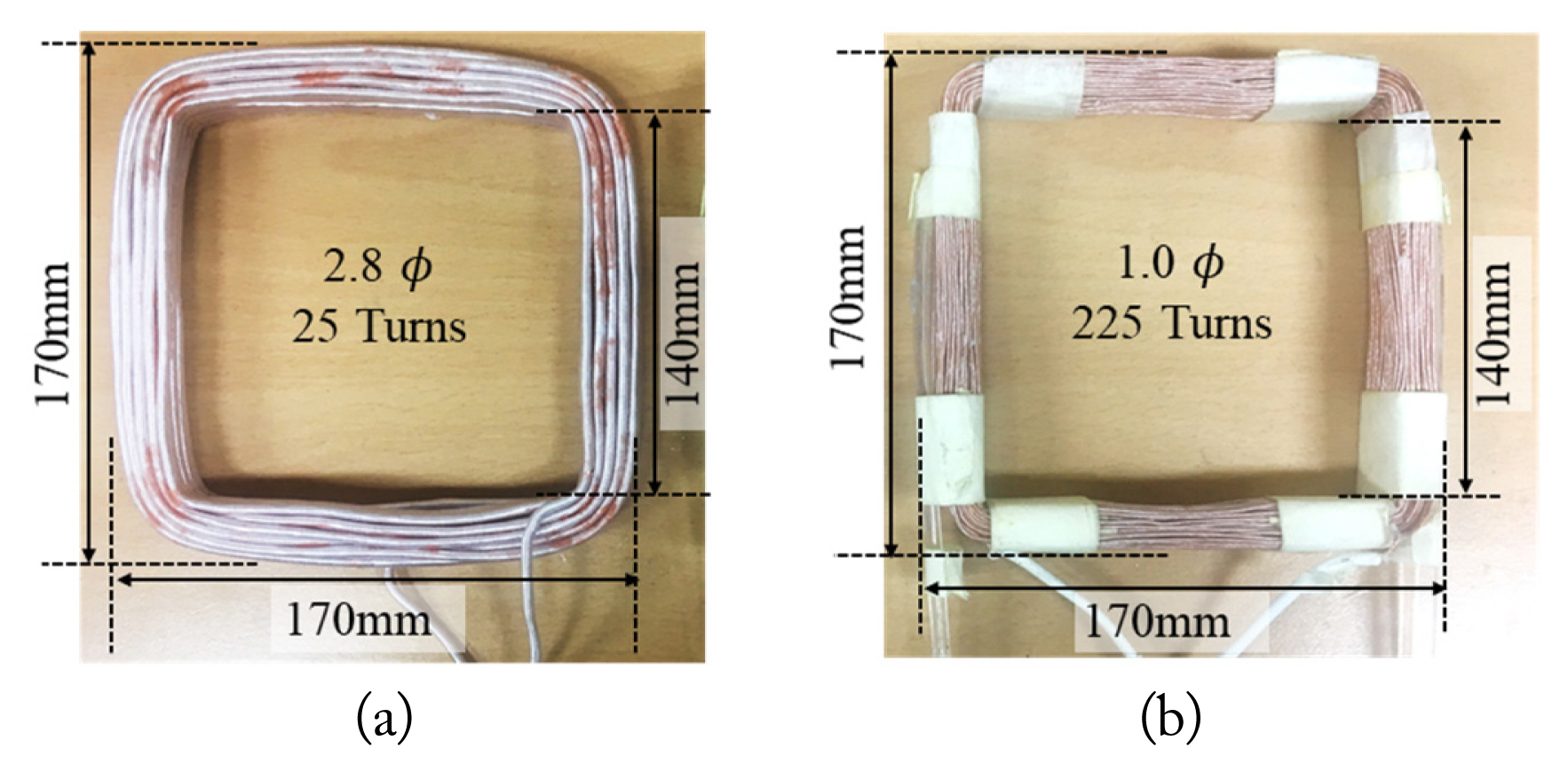
Fabricated transmitting coils. The outer and inner dimensions are restricted to 170 mm, and 140 mm respectively. (a) 2.8 φ-25 turns transmitting coil and (b) 1.0 φ-225 turns transmitting coil.
Fig. 7 describes the Q-factors of the two transmitting coils as measured by the VNA. The 225 turns-1.0 φ coil showed a lower Q-factor while the 25 turns-2.8 φ coil had a higher Q-factor. This is because a high number of turns introduces a proximity effect, increasing self-resistance. Moreover, as the number of turns increased, the parasitic capacitance between the wires also increased. For this reason, the SRF of the 225 turns-1.0 φ coil was observed to be around 220 kHz, and the Q-factor turned to negative above 220 kHz, which means that the electric characteristic of the coil enters the capacitive region.
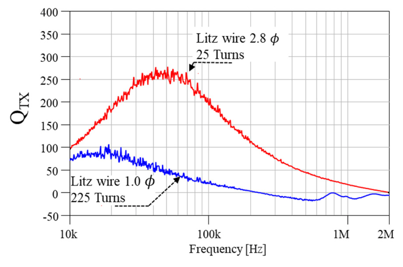
The Q-factors of the two transmitting coils. The measurements ranged from 10 kHz to 2 MHz.
However, the 2.8 φ Litz wire coil had higher Q-factors within the range of 10 kHz to 2 MHz.
3. Receiving Coil Analysis
Two 160 turns-0.1 φ and one 40 turns-0.2 φ receiving coils were fabricated. In the 160 turns coils, one coil was wound along a 2 mm × 2 mm × 4 mm magnetic bar, and the other was wound along a non-magnetic material as a support, producing an identical shape, as illustrated in Fig. 8(a) and 8(b).
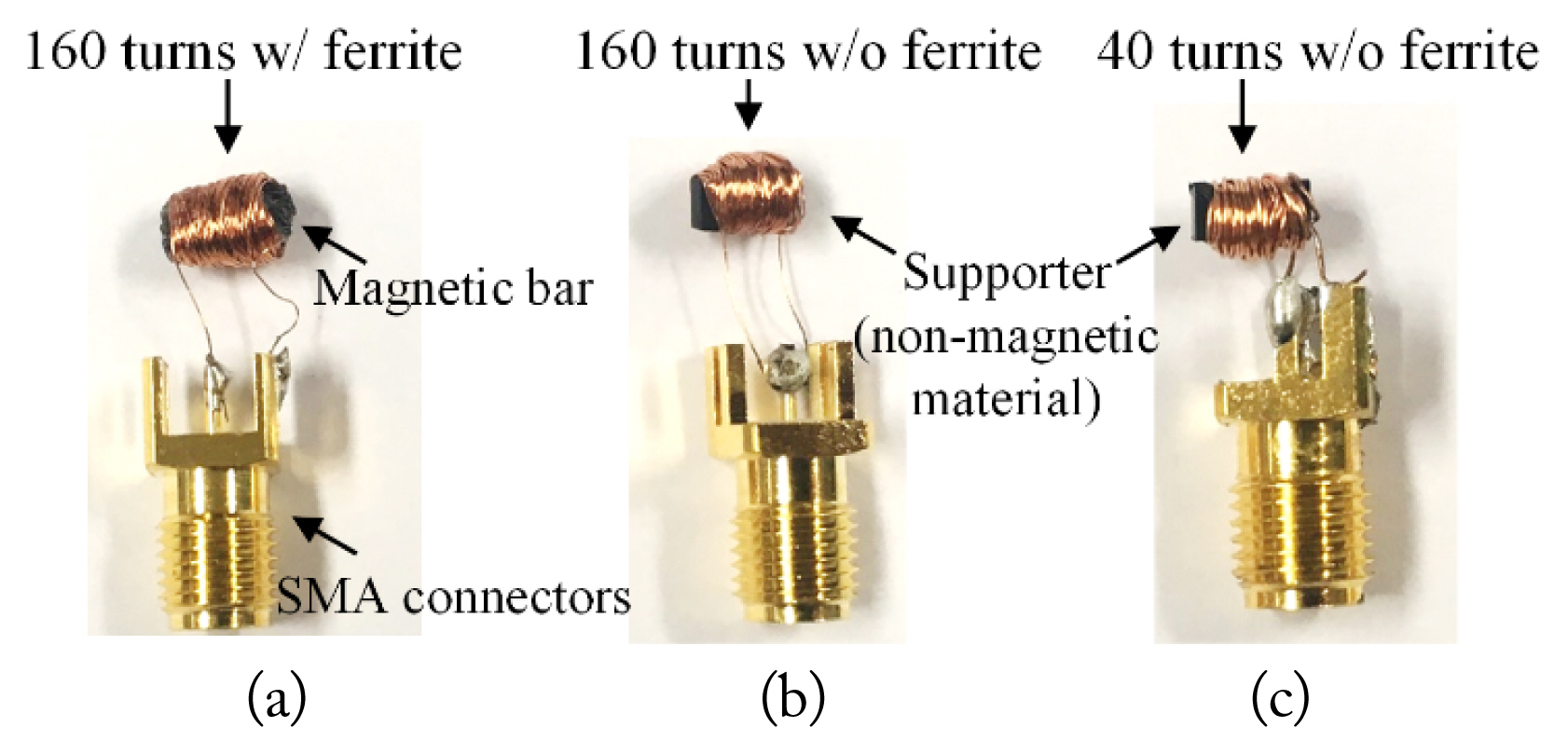
Three different fabricated receiving coils. For (a) and (b) the 160 turns-0.1 φ coil was wound along a 2 mm × 2 mm × 4 mm magnetic bar and a non-magnetic supporter, respectively. (c) The 40 turns-0.2 φ coil was wound along a 2 mm × 2 mm × 4 mm non-magnetic supporter.
The other power receiving coil, wound with 40 turns along a 2 mm × 2 mm × 4 mm supporter with 0.2 φ wire, is shown in Fig. 8(c). Sub-Miniature-version-A (SMA) connectors were applied to easily connect to the VNA. The magnetic bar was composed of multiple ferrite sheets, whose relative permeability was 150 in our frequency range of interest, from 10 kHz to 2 MHz [25, 26]. These ferrite sheets not only generate magnetic force but also concentrate the magnetic field. As a result, their self-inductance was around two times higher than the others. For this reason, the ferrite-embedded receiving coil had a higher Q-factor, as illustrated in Fig. 9.
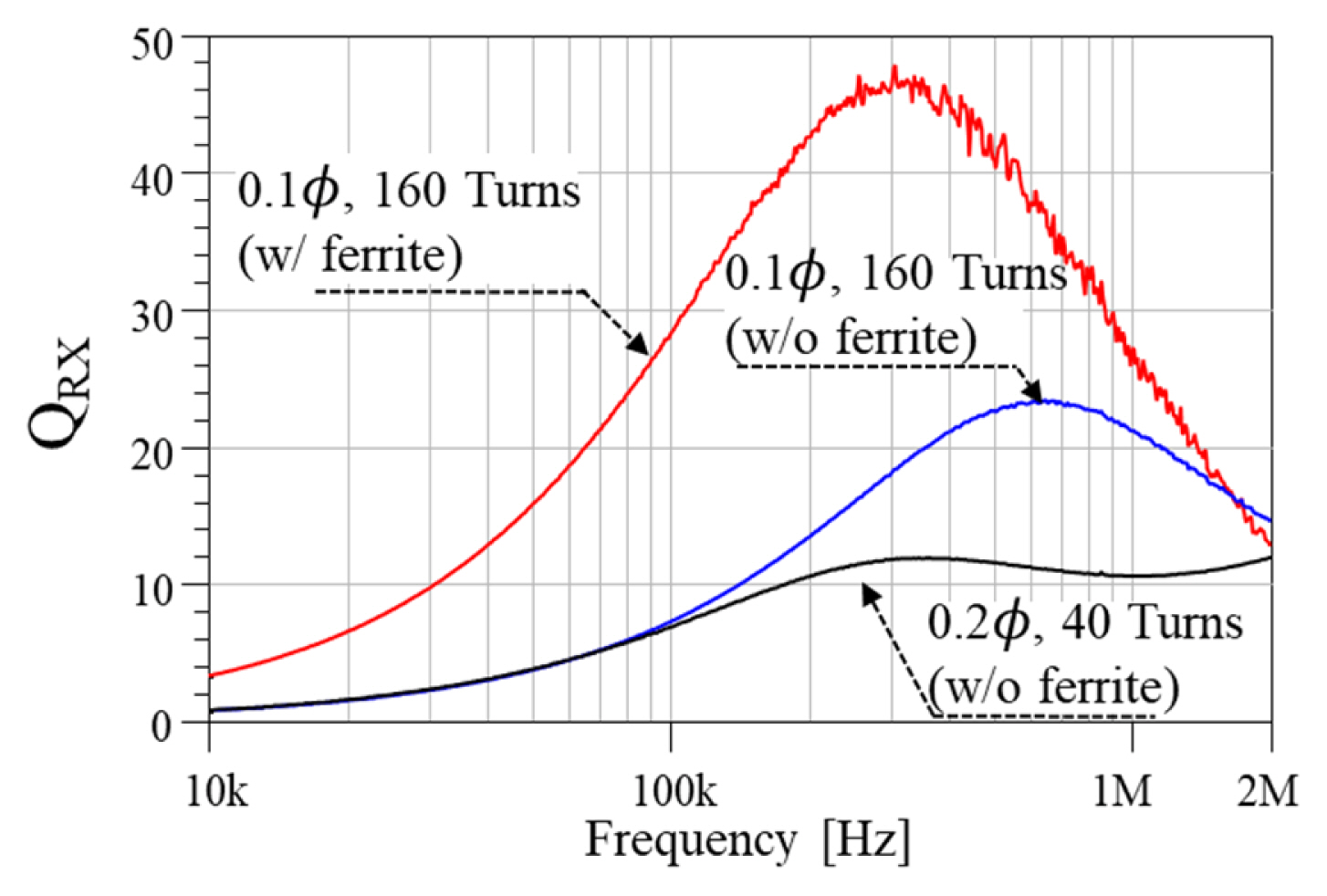
The Q-factor of the receiving coil from 10 kHz to 2 MHz.
4. Determining Powering Frequency
As the coupling coefficient is determined by the structure of the two coils and the magnetic material, a ferrite enclosed coil has values that are two times higher than coils without ferrite, as shown in Fig. 10.
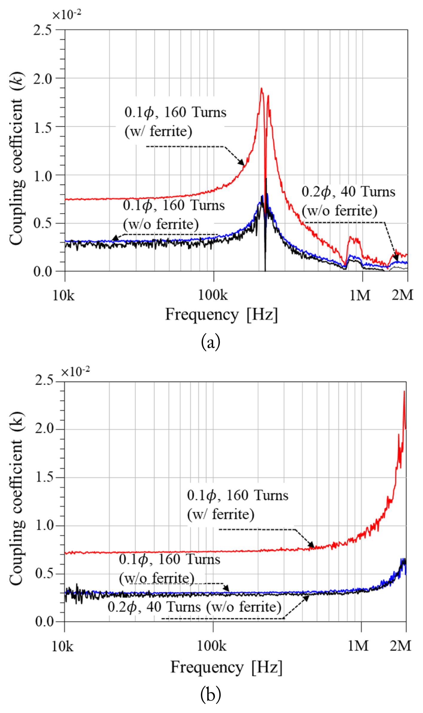
Measured coupling coefficients. (a) Coupling coefficient of 25 turns-2.8 φ coil for three different receiving coils and (b) coupling coefficient of 225 turns-1.0 φ coil with three different receiving coils. The receiving coil with ferrite material inserted showed a higher coupling coefficient.
Below 100 kHz, the coupling coefficient levels of the two coils were not very different, since their outer dimensions were very close to each other. Finally, by combining the Q-factors and coupling coefficient, the power transfer efficiency could be obtained according to Eq. (5) (see Fig. 11). The results indicated that the maximum power transfer that can be achieved was around 3.65% at 220 kHz with the 2.8 φ-25 turns transmitting coil and 160 turns ferrite embedded receiving coil and 0.87% at 100 kHz with 1.0 φ-255 turns. Because the powering frequency and magnetic force are independent, there is no restriction on the powering frequency. Accordingly, we could determine the powering frequency just by considering the power transfer efficiency, which is 220 kHz.
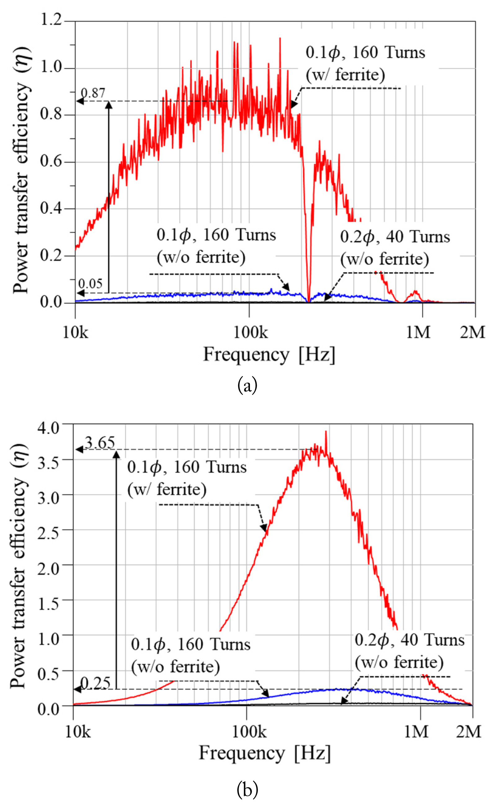
Measured coil to coil efficiency. (a) Efficiency of the transmitting with 1.0 φ-225 turns. (b) Efficiency of the transmitting coil with 2.8 φ-25 turns.
V. Experimental Validation
The feasibility of the proposed system was validated by an experiment. As illustrated in Fig. 12, the receiving coil was 5 cm away from the transmitting coil. To provide AC power, we used a 1 kW frequency-tunable inverter. To observe the power consumption of the coil, differential voltage and current probes were applied to the transmitting coil. Two sets of matching capacitor sets were prepared for the two transmitting coils. As the size of the receiving coil is very small, it was difficult to measure current and voltage. Alternatively, we observed how much power was consumed by the transmitting part to turn on a light-emitting diode (LED) on the receiving coil. To turn on the LED, we applied 30 W and 10 W to the 255- and 25-turn transmitting coils, respectively. This confirmed that the power transfer efficiency of the 25-turn transmitting coil was three times higher than the 225-turn coil. For this reason, a 25-turn transmitting coil was used for the propulsion experiment.
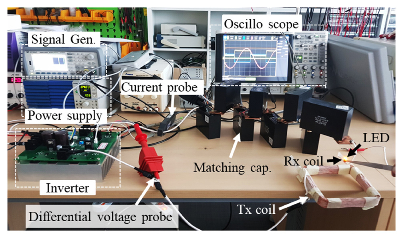
Experimental setup used for WPT verification. The receiving coil was located 5 cm away from the transmitting coil.
The microrobot was enclosed in a capsule and inserted into the oily media, as shown in Fig. 13. It included a receiving coil consisting of a magnetic bar wound with 160 turns. When the inverter was turned on, the microrobot began to move toward the transmitting coil and received the power, which was enough to turn on the LED attached to the microrobot. This occurs because a magnetic force always moves toward a magnetic field source, as described in Eq. (1). Additionally, regardless of powering frequency, the microrobot moved toward the transmitting coil, which supported Eq. (3).
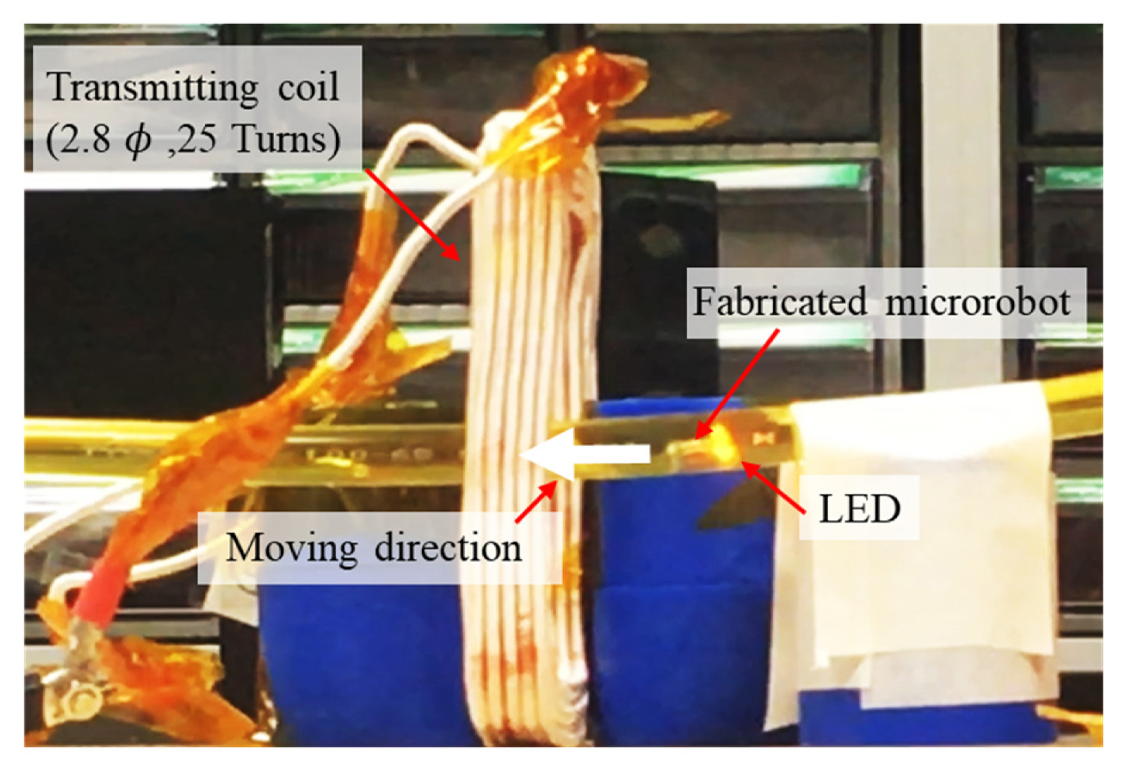
Microrobot propulsion experiment setup. The microrobot moves toward the transmitting coil due to the magnetic force between the transmitting coil and the magnetic bar, which is located in the receiving coil.
VI. Conclusion
This paper introduced a magnetic material-based microrobot propulsion system. To produce propulsion, we derived and analyzed the magnetic force applied to a magnetic bar using a WPT system. The proposed method was verified by a 3D electromagnetic (EM) simulation, and the results had a discrepancy of less than 9%. To achieve high power transfer efficiency, we analyzed the transmitting and receiving coils using Q-factor and coupling coefficient measurements. Using the results, we determined the optimal operating frequency and achieved 3.6% power transfer efficiency.
This work provides a basis for determining the effects of an incident current on a WPT microrobot system and for achieving high power transfer efficiency while reducing magnetic field radiation, which can be harmful to the human body.
Acknowledgments
This research was supported by a National Research Foundation of Korea (NRF) grant funded by the Korea government (No. NRF-2021R1G1A1004926) and partly supported by the Korea Electric Power Corporation (No. R20XO02-35).
References
Biography

Dongwook Kim received a B.Sc. in mechatronics engineering from the Tech University of Korea, Siheung, South Korea, in 2014, and a M.Sc. and Ph.D. from the Korea Advanced Institute of Science and Technology (KAIST), Daejeon, South Korea, in 2016 and 2019, respectively. In 2019 and 2020, he was a postdoctoral researcher with the Department of Mechanical Engineering Research Institute, KAIST, and the Department of Mechanical and Manufacturing Engineering, University of Calgary, AB, Canada. He is currently an assistant professor in the Department of Automotive Engineering, Yeungnam University, Gyeongsan, South Korea. His research interests include wireless power transfer systems in microrobots, implantable devices, and electric vehicles.

Seungyoung Ahn received his B.Sc., M.Sc., and Ph.D. in electrical engineering from the Korea Advanced Institute of Science and Technology (KAIST), Daejeon, South Korea, in 1998, 2000, and 2005, respectively. From 2005 to 2009, he was a Senior Engineer with Samsung Electronics, Suwon, South Korea, where he was in charge of high-speed board design for laptop computer systems. He is currently a professor with the Cho Chun Shik Graduate School of Mobility, KAIST. His research interests include wireless power transfer system design and electromagnetic compatibility design for electric vehicles and high-performance digital systems.