Investigation of an Axial Virtual Cathode Oscillator with an Open-Ended Coaxial Cathode
Article information
Abstract
A cathode with an open-ended coaxial structure is experimentally investigated using an axial virtual cathode oscillator (vircator). To enhance the microwave power output, an open-ended coaxial cathode is installed in the axial vircator. The proposed cathode is designed based on the reciprocating frequency of the vircator. The operation features of an axial vircator with a solid cathode, an annular cathode, and an open-ended coaxial cathode are comparatively analyzed through simulations and experiments. Three cathodes are machined using graphite. A stainless steel mesh with a transparency of 70% is used as an anode. The anode-to-cathode gap is fixed to 6 mm. The vircator is driven using a 10-stage PFN-Marx generator with a characteristic impedance of 31 Ω. The PFN-Marx generator applies −150 kV voltage pulses with a 170–200 ns pulse width into the vircator. The microwave power from the solid and annular cathodes is 11.22 MW and 11.27 MW, respectively. The proposed cathode generates a microwave with a power of 12.65 MW while enhancing the microwave power by 13% compared with the solid and annular cathodes. The proposed cathode shows a frequency shift to 3.4 GHz, which is a much lower frequency than that of the solid cathode at 6.34 GHz.
I. Introduction
As a high-power microwave (HPM) device, many vacuum electronic devices have been studied and analyzed [1, 2]. A virtual cathode oscillator (vircator) is one microwave source for an HPM device [3, 4]. The vircator generates microwaves from the oscillation of the virtual cathode and reciprocating motion of electrons between the cathode and anode. The advantage of using a vircator is its simple construction and capability for high-power and high-voltage operation. A disadvantage is its relatively low efficiency compared with other HPM sources, such as magnetrons or klystrons. Researchers have studied vircators to improve their low efficiency, analyze the modulation characteristics of the output frequency, and enhance the output power. Various types of vircators, such as the axial vircator, reflex triode vircator, and coaxial vircator, have been studied to improve the shortcomings of vircators [5–8]. In addition to studying the various types of vircators, reflectors, resonators, and various cathode structures have been studied by utilizing resonant mechanisms and varying the electron emission to increase vircator efficiency [9–13].
In the current paper, an open-ended coaxial structure, which is the resonant cavity, is applied to the cathode structure and investigated using an axial vircator. A cathode with an open-ended coaxial structure is fabricated to match the structural and operational frequencies of the axial vircator as a way to enhance microwave power. The proposed cathode is experimentally investigated by comparing it with a solid cathode and annular cathode. The modulation features and characteristics are analyzed by comparing the frequency and output power of the microwave signal from the proposed cathode with that of a solid cathode and annular cathode.
II. System Description
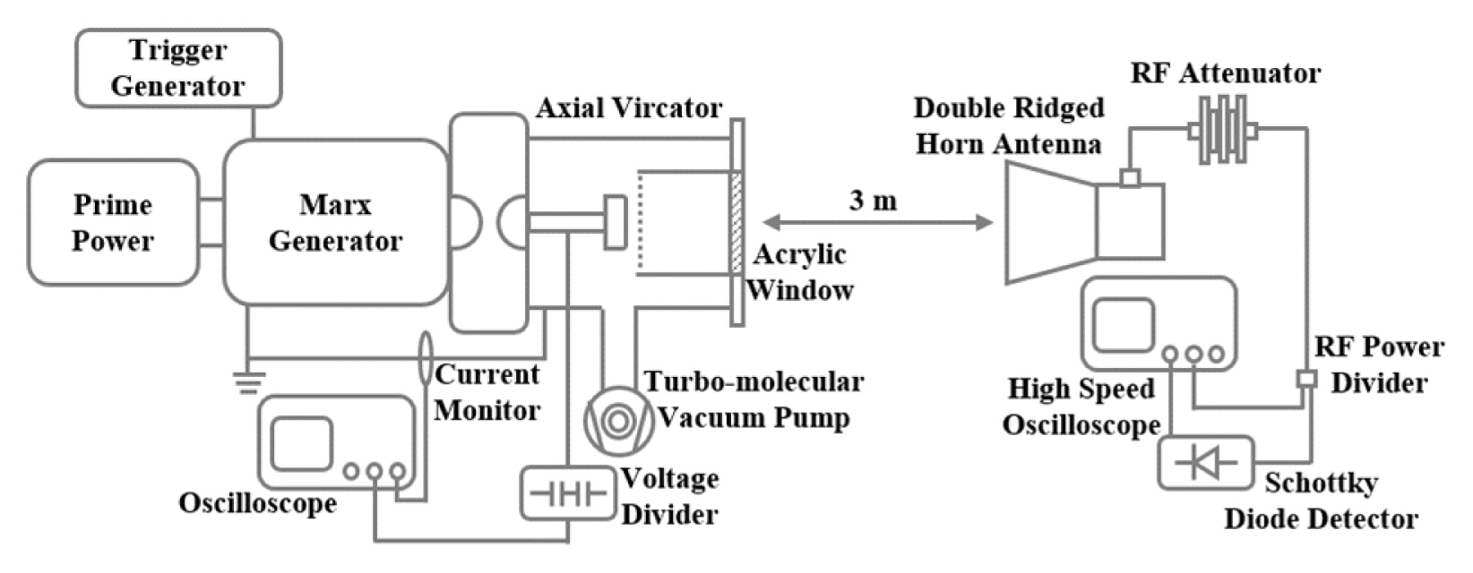
Fig. 1 shows a schematic diagram of the experimental system. The experimental system is composed of three subsystems: a pulsed-power system (PFN-Marx generator), a high-power microwave device (vircator), and a measurement system.
1. Pulsed-Power System
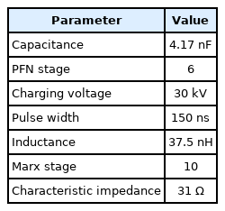
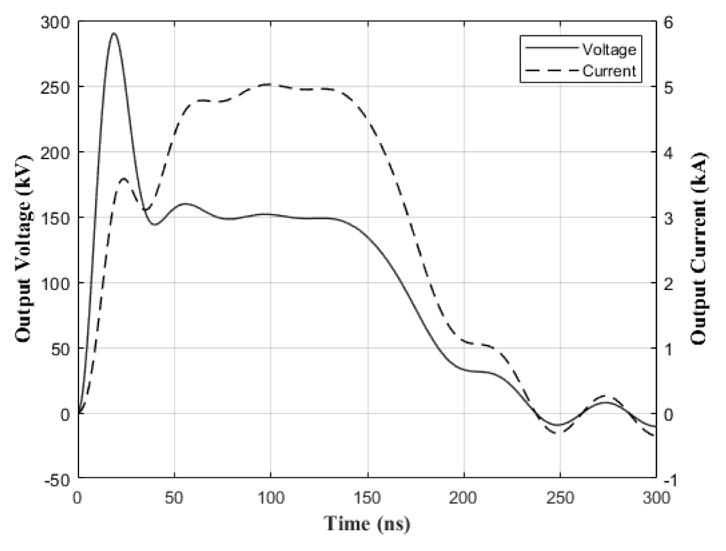
A 10-stage PFN-Marx generator is selected as a compact pulsed-power source. The characteristic impedance and pulse width of the PFN-Marx generator are 31 Ω and 150 ns, respectively. The capacitance and the inductance of the PFN module is 4 nF and 38 nH, respectively. Fig. 2 shows the equivalent circuit of the 10-stage PFN-Marx generator. Each PFN is charged negatively to −30 kV to produce a peak erected voltage of −300 kV on the vircator. The PFN-Marx generator is simulated using MATLAB/Simulink before the experiments. According to the literature, the impedance of the vircator is changed from an infinite value to 20–30 Ω during operation [14]. The equivalent impedance of the vircator is designed to vary from an infinite value to 25 Ω. The inductance and capacitance of the vircator section are 40 nH and 1.5 nF, respectively. The inductor represents the total parasitic inductance of the gap switch. The capacitor represents the capacitance of the vircator diode. The circuit parameters of the PFN-Marx generator are described in Table 1. Fig. 3 shows the voltage and current waveform of the PFN-Marx generator. The plateau voltage is used as a diode voltage in the finite difference time domain particle-in-cell (FDTD-PIC) simulation. In the experiments, the PFN-Marx generator is initiated by triggering a trigatron-type spark gap switch in the first stage.
2. High-Power Microwave Device
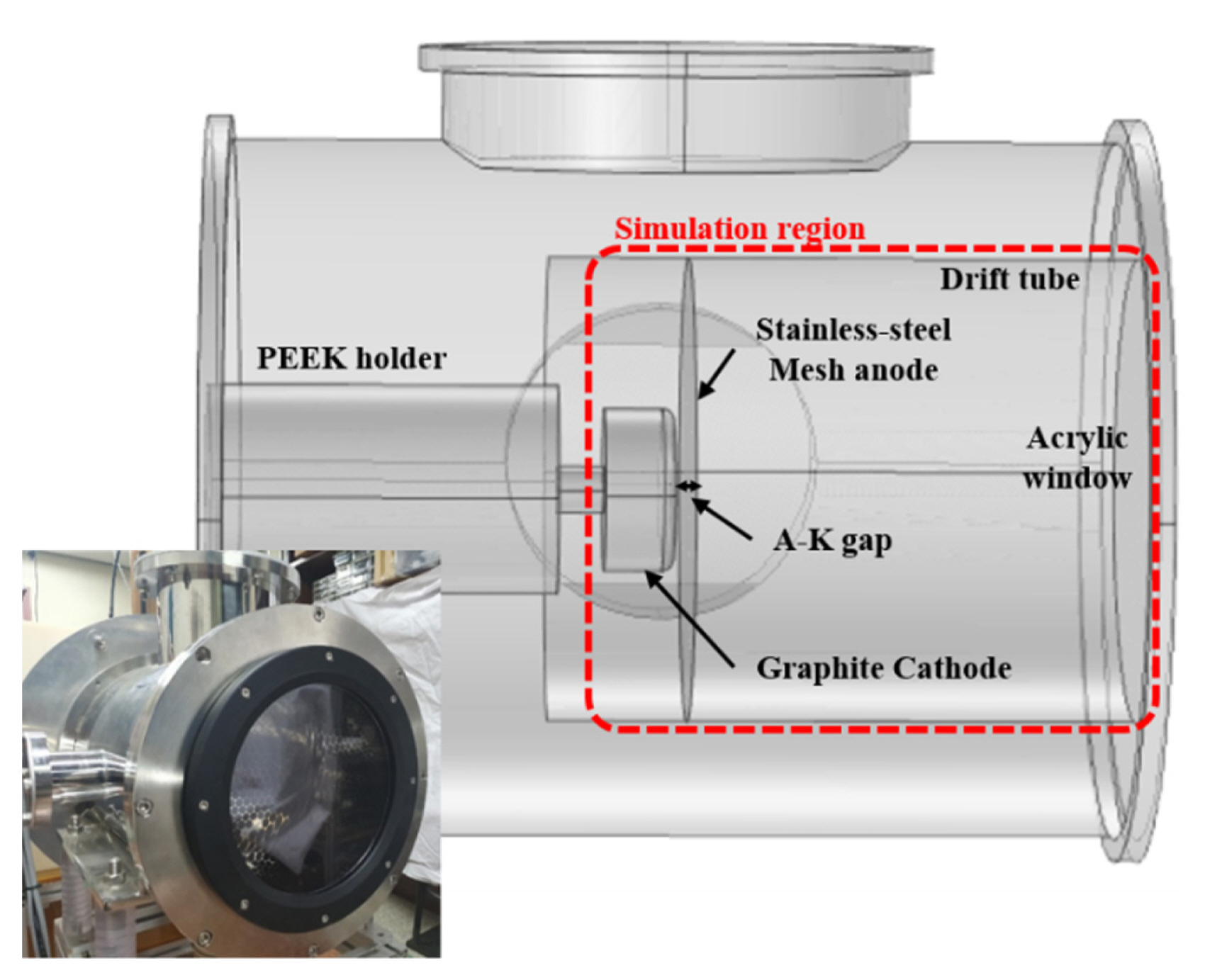
The axial vircator is housed in a stainless steel chamber with a 300-mm diameter and length of 400 mm. A drift tube with a 200-mm diameter is installed in the vircator chamber to attach an anode. The vircator chamber is evacuated using a turbo-molecular pump. The pressure of the chamber is maintained below 3 × 10⁻⁵ torr during the experiments. A poly-ether-ether ketone (PEEK) cathode holder is installed in the chamber to prevent electrical breakdown between the chamber and voltage feeder. The structure of the axial vircator is shown in Fig. 4.
Serving as a vircator diode, a graphite cathode and a stainless steel mesh anode are installed in the vircator chamber. The diameters of the cathode and the anode are 70 mm and 200 mm, respectively. The thickness of the anode is 0.2 mm. The mesh anode is fabricated to have a geometric transparency of 70%. The anode-to-cathode distance is fixed at 6 mm.
3. Measurement System
The diode voltage, diode current, and microwave signal of the axial vircator are measured to analyze the operation features of the open-ended coaxial cathode. A capacitive voltage divider and Pearson coil are installed in the feedthrough to measure the diode voltage and diode current. The voltage and current waveforms are recorded using an oscilloscope (DPO3054; Tektronix Inc., Beaverton, OR, USA).
A double-ridged horn antenna is placed 3 m away from the vircator window to measure microwave intensity. A 40-dB attenuator is installed after the antenna to protect the oscilloscope and attenuate the microwave to an observable level. For the open-ended coaxial cathode, the total attenuation of the RF measuring system is 59 dB, including attenuation at the RF cable and insertion loss at the RF power divider. The RF power divider is used to divide the microwave signal to analyze the frequency and microwave power. The frequency is analyzed using a high-speed oscilloscope (MSO71604C; Tektronix Inc.). The microwave power is measured using a low-barrier Schottky diode detector (423B; Keysight Technologies, Santa Rosa, CA, USA) and oscilloscope (DPO3054; Tektronix Inc.). The diode detector converts the microwave power into a voltage and generates an envelope waveform of the microwave. The microwave power at the axial vircator is calculated using the Friis transmission equation [15]. The transmitting antenna gain is estimated using the CST (Computer Simulation Technology) Microwave Studio and used in the power calculations. The antenna gains of the transmitting and receiving antennas are 18.5 dBi and 12 dBi, respectively.
III. Design of Open-Ended Coaxial Cathode
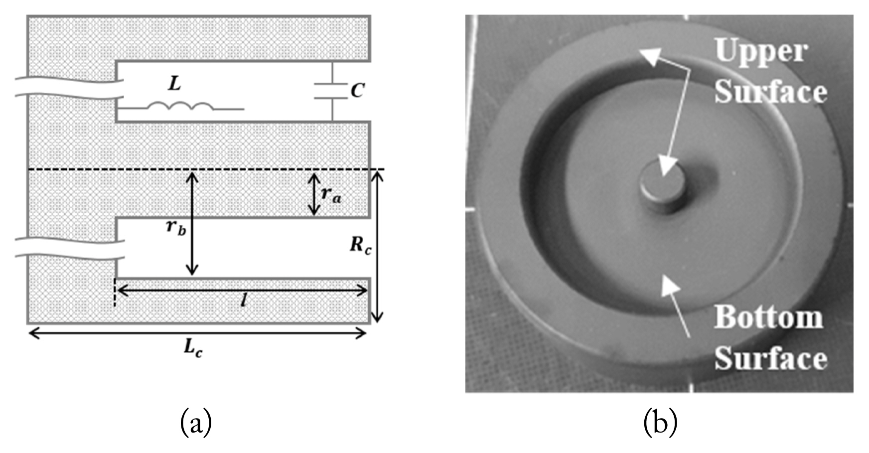
The open-ended coaxial structure can be used as a resonant cavity. The structure of the open-ended coaxial cathode is shown in Fig. 5(a). In the current paper, an open-ended coaxial structure is applied to the cathode to enhance the operation features of the axial vircator.
The frequency of the vircator is calculated to design the openended coaxial cathode. The vircator has two microwave frequencies: the oscillation frequency of the virtual cathode and the reciprocating frequency of the electrons between the anode and cathode [16]. Because the vircator is operated at a nonrelativistic voltage (Vdiode < 0.5 MV), the virtual cathode oscillation frequency (fvc) and reciprocating frequency of the electrons between the cathode and the virtual cathode (fr) are give n as follows:
where e is the electron charge, m is the electron mass, d is the anode-to-cathode distance (A-K gap) in centimeters, and V is the diode voltage. With parameters of d = 0.6 cm and V = 150 kV (the voltage level at the flat top), the virtual cathode oscillation frequency and reciprocating frequency are calculated as 7.18 GHz and 6.07 GHz, respectively. According to the experimental results obtained from the solid cathode described in the next section, the dominant frequency of the vircator with the solid cathode is close to the reciprocating frequency. The reciprocating frequency is used in designing the proposed cathode.
Fig. 5(b) shows a picture of the open-ended coaxial cathode. The resonant frequency of the open-ended coaxial structure is given as follows:
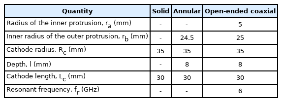
where c is the speed of the light, l is the depth of the open-ended structure, ra is the radius of the inner protrusion structure, and rb is the inner radius of an outer protrusion structure. According to Eq. (3), the resonant frequency of the open-ended coaxial structure depends only on its depth. The resonant frequency calculated through Eq. (3) is used to match the vircator frequency and structural frequency. In the current study, the open-ended coaxial cathode and the annular cathode are designed to have the same depth to analyze the resulting effects on the axial vircator. The depths of the open-ended coaxial cathode and annular cathode are calculated based on the reciprocating frequency of the vircator. The depth for 6.07 GHz is 8 mm. Table 2 shows the specifications of the cathodes used in the experiments.
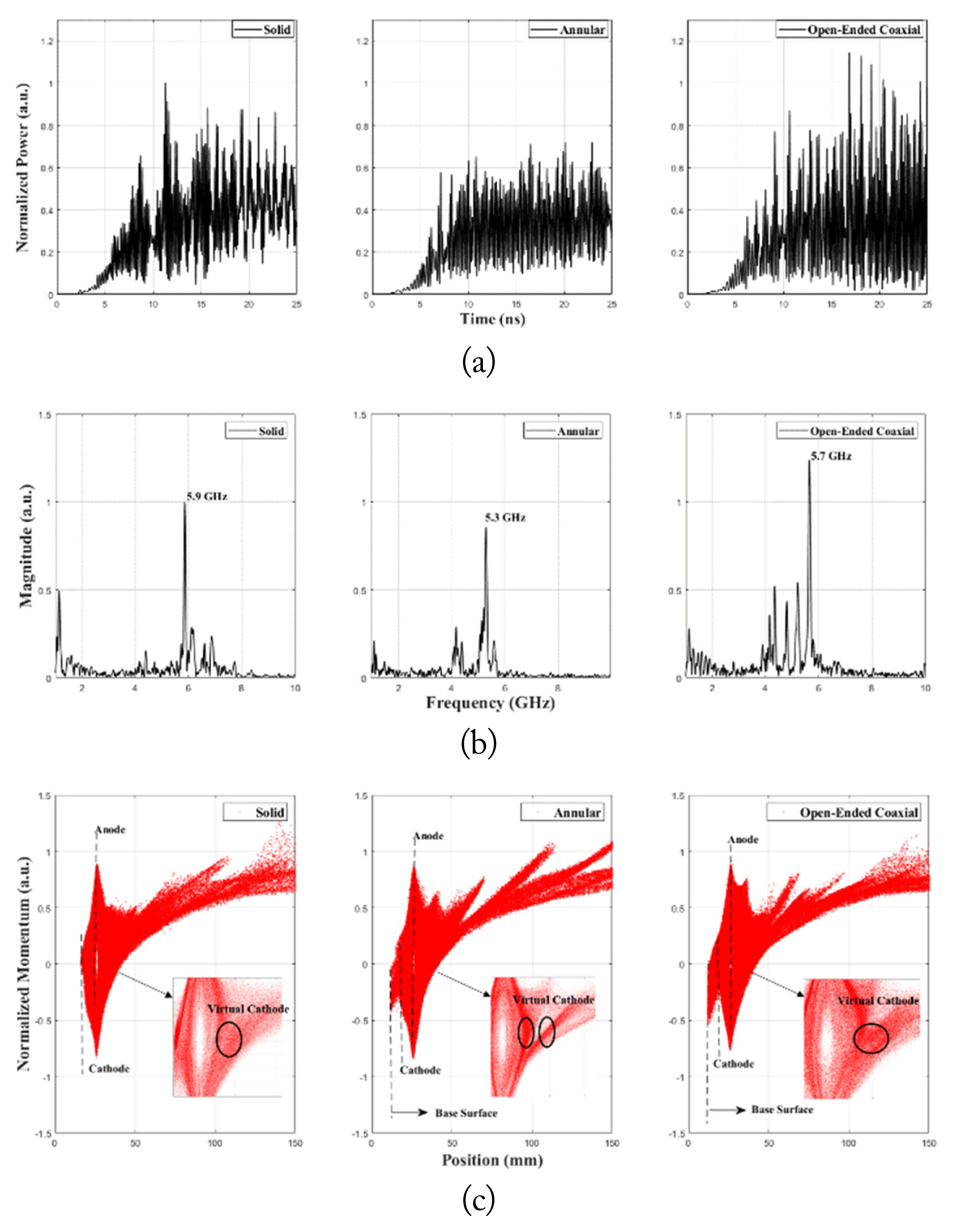
The open-ended coaxial cathode and solid cathode are analyzed before the experiments using a FDTD-PIC simulation (CST Particle Studio). The simulation space is designed based on a cross-sectional diagram, which is shown in Fig. 4. In simulations, the remaining region, save for the marked simulation region, is excluded. The diameter and length of the simulated drift tube are 200 mm and 300 mm, respectively. The threshold voltage for electron emission is set to 100 kV/m. The mesh anode is modeled as a thin sheet with a transparency of 70%. A ramp-shaped −150 kV voltage pulse with a pulse width of 25 ns which is a consequence of the MATALB/Simulink results for the PFN-Marx generator is used as the diode voltage. In the simulation, the beam emitting surface is constrained to the upper surface for the annular cathode and the open-ended coaxial cathode. Fig. 6 shows the simulation results for the solid cathode, annular cathode, and open-ended coaxial cathodes. Three cathodes are operated in TM01 mode. Fig. 6(a) shows the normalized microwave power for the three cathodes. The microwave power is normalized based on the solid cathode results. According to the simulations, the annular cathode produces 28% lower microwave power than the solid cathode. However, the proposed cathode produces 15% higher microwave power than the solid cathode. The fast Fourier transform (FFT) results are shown in Fig. 6(b). Significant power is observed at 5.9 GHz, 5.2 GHz, and 5.7 GHz for the solid, annular, and open-ended coaxial cathodes, respectively. Fig. 6(c) shows the normalized momentum of the electrons for the three different cathodes. According to the phase space diagram, the three cathodes show different virtual cathode formations. For the solid cathode, a virtual cathode is formed in space around 6 mm away from the anode. The annular cathode creates two virtual cathodes at spaces around 7 mm and 9 mm away from the anode. The second virtual cathode formed at 9 mm is the reason for behind small peak shown at 4 GHz. Unlike two cathodes, the open-ended cathode creates one virtual cathode that has its region from 6 mm to 9 mm away from the anode. The virtual cathode is denser at the front and sparser at the back. Because the virtual cathode region is extended along the axis, several peaks are shown between 4 GHz and 5.7 GHz. However, because the virtual cathode is denser at the front, the dominant frequency is close to the solid cathode’s frequency compared with the annular cathode. In addition, the electron momentum between the cathode and virtual cathode is the highest when the proposed cathode is used. The proposed cathode is considered to enhance microwave power through increased electron momentum.
IV. Experimental Results and Analysis
An open-ended coaxial cathode is investigated to determine whether it improves the operation features of the vircator. The typical voltage and current waveforms obtained are shown in Fig. 7. From the figure, it can be seen that the peak voltage is about −200 kV, and the voltage over the relatively flat portion is −150 kV. The rise time and pulse width of the voltage pulse are 25 ns and 200 ns, respectively. The peak current is −5.56 kA.
The microwave power and frequency at the receiving antenna are used to calculate the microwave power generated from the vircator. Fig. 8 shows the typical diode detector output voltages for three different cathodes. The frequency spectra of the three cathodes are shown in Fig. 9. The frequency with the largest magnitude is used for calculating the Friis transmission equation. Because attenuation at the RF cable differs based on the frequency, the three different attenuations are used in the microwave power calculations. Although it has several other small peaks between 5.5 GHz and 7 GHz, the dominant frequency of the solid cathode is 6.34 GHz. For the annular and open-ended coaxial cathodes, the dominant frequencies are 3.2 GHz and 3.4 GHz, respectively. The cylindrical and annular holes in the cathodes form a bottom surface and increase the distance between the anode and cathode. According to Eqs. (1) and (2), the vircator frequency is inversely proportional to the anode-to-cathode distance. In addition, the simulation shows that the emitted electrons reciprocate between the virtual cathode and both the upper and bottom surfaces of the cathode. The increased reciprocating distance because of the hole in the cathode causes the frequency to shift from a higher dominant frequency to a lower dominant frequency. From the frequency spectrum, it can be seen that the annular cathode has more concentrated microwave generation, and a small peak is observed at 5.8 GHz. Unlike the annular cathode, the proposed cathode has a broad frequency spectrum around 3.4 GHz and small peaks around 5 GHz. As shown in the simulations, the annular cathode has a more concentrated frequency compared with the proposed cathode, and the proposed cathode has several peaks around the dominant frequency. However, the major difference between the simulations and experimental results is the dominant frequency. Although the frequency shift was expected to some degree, the experimental results show that the dominant frequency is formed at a much lower frequency region. Because the voltage is practically the same during microwave generation, it can be deduced that most of the emitted electrons are reciprocating the longer distance than in the simulation.
Fig. 10 shows the microwave powers for the solid, annular, and open-ended coaxial cathodes. The average microwave powers from the solid, annular, and open-ended coaxial cathodes are 11.22 MW, 11.27 MW, and 12.65 MW, respectively. Unlike the simulations, the annular cathode generates the same amount of average microwave power compared with the solid cathode. The open-ended coaxial cathode enhances microwave power by 13%. From the deviations in the microwave power, it can be seen that the proposed cathode generates a more consistent microwave compared with the other cathodes. In addition, the three cathodes have different geometric factors. These geometric factor affects the space charge limited current, resulting in a change in microwave power. In addition to the cavity condition, the geometric factor of the proposed cathode affects microwave power enhancement. The simulated efficiencies of the solid, annular, and proposed cathodes are 1.41%, 1.11%, and 2.08%, respectively. The experimental efficiencies of the solid, annular, and proposed cathodes are 1.37%, 1.38%, and 1.55%, respectively. The efficiency difference between the simulations and experiments is caused by the difference in the beam current of the simulations and experiments.
V. Conclusion
The current paper proposes a cathode with an open-ended coaxial structure to enhance microwave power from an axial vircator. The operation features of the proposed cathodes are compared with those of the solid and annular cathodes through simulations and experiments. The vircator is driven using a 10-stage PFN-Marx generator. The microwave peak is achieved when the diode voltage is around −155 kV and current is at −5.5 kA. The proposed cathode generates a microwave with a peak power of 12.65 MW and a dominant frequency of 3.4 GHz. The experimental results show that the proposed cathode enhances microwave power by 13% compared with the solid and annular cathodes, and the dominant frequency shifts to a lower frequency. When a solid cathode is used, a larger A-K gap needs to be used to generate a microwave with a lower frequency. The larger A-K gap is accompanied by an increase in the operating voltage. However, the proposed cathode allows for the generation of a microwave with a lower frequency, without increasing the operating voltage. Therefore, we expect that the proposed cathode can be used to enhance and modulate the microwave output from axial vircators. In future experiments, we intend to investigate the effects of the geometric factor of the proposed cathode on the operation features of the axial vircator by changing the inner radius, the outer radius, and the depth of the open-ended coaxial cathode.
References
Biography

Se-Hoon Kim received a B.S. degree in Electrical Engineering from Hanyang University, Seoul, Korea, in 2015. He is currently working toward his Ph.D. degree with the Applied High-power Engineering Laboratory in the Department of Electrical Engineering at Hanyang University, Korea. His current research interests include the compact pulsed-power system, the high-power microwave system, and their applications.

Chang-Jin Lee received a B.S. degree in Electrophysics from Hallym University, Chuncheon, Korea in 2015, and a Ph.D. degree from Hanyang University, Seoul, Korea, in 2022. He is currently working as an engineer at Kyuong-bu Electricity Safety Management. His current research interests include power quality and electric power management.

Wan-Il Kim received a B.S. degree in Electrical Engineering from Hankyong University, Korea, in 2016, and then received a M.S. degree from Korea National University of Transportation in 2018. He is currently pursuing a Ph.D. degree with the Department of Electrical Engineering at Hanyang University, Korea.

Kwang-Cheol Ko received a B.S. degree in Electrical Engineering from Hanyang University, Seoul, Korea, in 1982, and M.S. and Ph.D. degrees from the Tokyo Institute of Technology, Tokyo, Japan, in 1986 and 1989, respectively. From 1990 to 1995, he was an Assistant Professor with the Department of Electrical Engineering, Kyungwon University, Seongnam, South Korea. In 1995, he joined the faculty of the Department of Electrical Engineering, Hanyang University, where he is currently a professor. His current research interests include pulsed-power technologies and their applications.
